EP0068956B1 - Coupe-circuit à préhenseur et interrupteur de sectionnement - Google Patents
Coupe-circuit à préhenseur et interrupteur de sectionnement Download PDFInfo
- Publication number
- EP0068956B1 EP0068956B1 EP19820401056 EP82401056A EP0068956B1 EP 0068956 B1 EP0068956 B1 EP 0068956B1 EP 19820401056 EP19820401056 EP 19820401056 EP 82401056 A EP82401056 A EP 82401056A EP 0068956 B1 EP0068956 B1 EP 0068956B1
- Authority
- EP
- European Patent Office
- Prior art keywords
- fuse holder
- fuse
- actuating element
- circuit breaker
- gripper
- Prior art date
- Legal status (The legal status is an assumption and is not a legal conclusion. Google has not performed a legal analysis and makes no representation as to the accuracy of the status listed.)
- Expired
Links
- 238000000605 extraction Methods 0.000 claims description 17
- 210000000617 arm Anatomy 0.000 claims 2
- OIRDTQYFTABQOQ-UHTZMRCNSA-N Vidarabine Chemical compound C1=NC=2C(N)=NC=NC=2N1[C@@H]1O[C@H](CO)[C@@H](O)[C@@H]1O OIRDTQYFTABQOQ-UHTZMRCNSA-N 0.000 claims 1
- 230000011664 signaling Effects 0.000 description 5
- 238000009434 installation Methods 0.000 description 4
- 230000000694 effects Effects 0.000 description 2
- 230000007935 neutral effect Effects 0.000 description 2
- 210000000056 organ Anatomy 0.000 description 2
- 230000005489 elastic deformation Effects 0.000 description 1
- 238000002955 isolation Methods 0.000 description 1
- 238000012423 maintenance Methods 0.000 description 1
- 229910052751 metal Inorganic materials 0.000 description 1
- 239000002184 metal Substances 0.000 description 1
- 230000000149 penetrating effect Effects 0.000 description 1
- 230000002787 reinforcement Effects 0.000 description 1
- 229910052709 silver Inorganic materials 0.000 description 1
- 239000004332 silver Substances 0.000 description 1
Images

Classifications
-
- H—ELECTRICITY
- H01—ELECTRIC ELEMENTS
- H01H—ELECTRIC SWITCHES; RELAYS; SELECTORS; EMERGENCY PROTECTIVE DEVICES
- H01H85/00—Protective devices in which the current flows through a part of fusible material and this current is interrupted by displacement of the fusible material when this current becomes excessive
- H01H85/54—Protective devices wherein the fuse is carried, held, or retained by an intermediate or auxiliary part removable from the base, or used as sectionalisers
- H01H85/545—Protective devices wherein the fuse is carried, held, or retained by an intermediate or auxiliary part removable from the base, or used as sectionalisers with pivoting fuse carrier
-
- H—ELECTRICITY
- H01—ELECTRIC ELEMENTS
- H01H—ELECTRIC SWITCHES; RELAYS; SELECTORS; EMERGENCY PROTECTIVE DEVICES
- H01H9/00—Details of switching devices, not covered by groups H01H1/00 - H01H7/00
- H01H9/10—Adaptation for built-in fuses
- H01H9/104—Adaptation for built-in fuses with interlocking mechanism between switch and fuse
-
- H—ELECTRICITY
- H01—ELECTRIC ELEMENTS
- H01H—ELECTRIC SWITCHES; RELAYS; SELECTORS; EMERGENCY PROTECTIVE DEVICES
- H01H85/00—Protective devices in which the current flows through a part of fusible material and this current is interrupted by displacement of the fusible material when this current becomes excessive
- H01H85/0078—Security-related arrangements
- H01H85/0091—Security-related arrangements providing disconnection of the neutral line
Definitions
- the present invention generally relates to gripper circuit breakers, that is to say circuit breakers comprising, in a body, a member, called gripper, which has a recess suitable for housing a cartridge. fuse, and which is rotatably mounted in said body between a closed position, for which said fuse cartridge establishes an electrical connection between two contacts interposed between two connection terminals, and an extraction position, for which, this electrical connection being interrupted , said housing opens to the outside, for fitting or removing such a cartridge.
- gripper circuit breakers which further comprise, in their body, a sectioning switch interposed between two other connection terminals, said sectioning switch being normally open and being capable of being ordered to close. by the gripper, when said gripper is itself in the closed position.
- This intermediate member is carried by the body, while being movably mounted thereon.
- circuit-breaker In general, it is advantageous to equip the circuit-breaker with a gripper with means, commonly called indicators of the presence of a fusible cartridge, capable of signaling the possible absence of such a cartridge when the gripper is in the closed position. .
- the present invention generally relates to a provision which, on the contrary, and advantageously very simple, makes it possible to take advantage of the presence of the isolating switch to perform the function of indicating the presence of a fuse cartridge wanted.
- the present invention relates to a gripper circuit breaker, of the type comprising in a body, on the one hand, a member, called gripper, which has a recess specific to the housing of a fuse cartridge, and which is rotatably mounted in said body between a closed position, for which said cartridge establishes an electrical connection between two contacts interposed between two connection terminals, and an extraction position, for which said housing opens out of said body, for fitting or removing such a cartridge, and, on the other hand, a sectioning switch interposed between two other connection terminals, said sectioning switch being normally open and being capable of being closed by the gripper when said gripper is itself in the closed position, characterized in that, for action on the sectioning switch, the gripper carries an actuating element, which is movably mounted on said gripper between a deployed position, for which, in the presence of a fuse cartridge, it is effectively capable of controlling the closing switch to close, and a retracted position, for which, in the absence of 'Such a fuse
- the actuating element that thus carries, according to the invention, the gripper is a bent lever, which is pivotally mounted on said gripper, and which has two arms, namely a first arm capable of penetrating the recess that has said gripper for housing a fuse cartridge, and a second arm capable of controlling the closing of the associated disconnecting switch either directly or indirectly, via an intermediate member.
- any signaling means is mounted in series on the circuit controlled by this isolation switch.
- It may be, for example, the coil of a contactor capable of controlling a signaling, indicator or other device.
- fig. 1 is an elevational view of a gripper circuit breaker according to the invention, from which a part of the body has been assumed to be removed, and from which the gripper has been shown in the extraction position, in the absence of any fusible cartridge ;
- fig. 2 is, on a different scale, a partial perspective view of this gripper illustrating the actuating element with which it is equipped according to the invention
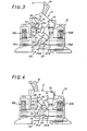
- fig. 3 is a view similar to that of FIG. 1, for a position of the intermediate gripper between its extraction position and its closed position;
- fig. 4 is a view similar to that of FIG. 1, for the closed position of the gripper;
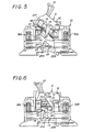
- fig. 5 and 6 are views respectively similar to those of FIGS. 3 and 4, when a fuse cartridge is present in the gripper.
- a body 10 or casing usually consisting of two shells, which are suitably facing one another along a common median plane and suitably subject to each other thus faced, and one of which was assumed to be removed in the figures, is mounted a rotary, or more precisely tilting, a member 11, said gripper, which comprises for this purpose, laterally, pins 12 pivotally engaged in said shells, and which has a recess 13 suitable for housing a fuse cartridge 14.
- a handle 15 is integral with this gripper, which, at the disposal of the user, is capable of allowing it to be maneuvered, and which, for this purpose, projects out of the body 10, by means of an opening 16 which has in front this one; under the control of this lever 15, the gripper 11 is rotatable in the body 10 between an extreme closed position, for which, as shown in FIG. 6, the fuse cartridge 14, when present, establishes an electrical connection between two contacts 17A, 17B interposed between two connection terminals 18A, 18B, and an extraction position for which, as shown in FIG. 1, the recess 13 presented by such a gripper 11 for housing a fuse cartridge 14 opens to the outside through the opening 16 of the body 10, for fitting or removing such a fuse cartridge 14 in such a obviously 13.
- the contacts 17A, 17B are each generally in the form of a cradle, each of these contacts 17A, 17B being formed, as shown diagrammatically in broken lines in FIG. 2 for the contact 17A, by two elastically deformable metal contact blades 20, which are arranged generally parallel to one another in the body 10.
- the gripper 11 scans the gap between the blades 20 constituting each of the contacts 17A, 17B, so that, when a fuse cartridge 14 is present in its recess 13, this fuse cartridge 14 comes, by its end caps 21 A, 21 B, to be inserted between the blades 20 constituting the corresponding contacts 17A, 17B, by elastic spacing of these blades.
- connection terminals 24A, 24B are simply formed by the ends of two contact blades 25A, 25B, which, embedded in the body 10 at their said ends, themselves form the disconnection switch 23 at their other ends.
- This disconnection switch 23 is normally open, and it can be ordered to close by the gripper 11 when the latter is itself in the closed position.
- an intermediate member 25 is provided for this purpose; disposed between the gripper 11 and the disconnection switch 23, it is carried by the body 10 and is mounted movable therein.
- this intermediate member 25 is constituted by a bent lever, which is pivotally mounted by its elbow in the body 10 and for this purpose laterally carries pins 26 pivotally engaged in the shells constituting the latter, and which has two arms, each respectively disposed on either side of its elbow, namely an arm 27, on which the gripper 11 is capable of acting when it is in the closed position, and an arm 28, by which it is itself capable of acting on the isolating switch 23 to control it in the closed position.
- the body 10 has a sole 29, suitable for being subject to any support rail, for example using a lock 30 mounted movably against a return spring 31.
- the gripper 11 for action on the sectioning switch 23, the gripper 11 carries an actuating element 33, which is movably mounted on said gripper 11, between a deployed position, for which, in the presence of a fuse cartridge 14, and as shown in FIG. 6, it is effectively able to order in closing the disconnection switch 23, according to the arrangements detailed below, and a retracted position, for which, in the absence of such a fuse cartridge 14, and as shown in FIG. 4, it is incapable of controlling said sectioning switch 23 to close.
- the actuating element 33 thus carried by the gripper 11 forms a bent lever, which, by its elbow, is mounted to pivot freely, frictionally, on the gripper 11, and which has two arms 34 , 35 each extending respectively on either side of its elbow, namely a first arm 34 able to penetrate into the recess 13 presented by the gripper 11 for housing a fuse cartridge 14, and a second arm 35 suitable for controlling the closing switch 23.
- the cutting element 33 constitutes, for the gripper 11, a nose disposed in a region thereof, the path of which sweeps the gap between the blades 20 constituting the contact 17A, which is that intended to cooperate with the base 21 A immediately accessible from the fuse cartridge 14 when the gripper 11 is in the extraction position.
- the region in question of the gripper 11 is therefore formed by that of the ends of the edge of the recess 13 furthest from the lever 15 which is closest to the opening 16 of the body 10 when the gripper 11 is in the position of extraction.
- the gripper 11 has transversely, at the end in question, a shoulder 36 on the median zone from which protrudes an ear 37, and the lever constituting the actuating element 33 forms overall a yoke 38 by which it is engaged on this ear 37, a pivot axis 39 transversely passing through said yoke and said ear.
- Each of the arms 34, 35 of this lever therefore consists of two parallel arm elements, each arranged respectively on either side of the lug 37 on which they are articulated.
- the shoulder 36 of the gripper 11 is capable of defining at least one of the positions, deployed or retracted, of the actuating element 33, and, in practice, by pressing one or the other of the arms of the lever constituting this actuating element 33, it is capable, in the embodiment shown, of defining one and the other of the positions, deployed and retracted, of this- this.
- the arm 34 carries, in the embodiment shown, a rounded boss 41.
- the actuating element 33 has transversely a width L1 slightly greater than that L2 of the gap between the blades 20 constituting the contact 17A when these are at rest ( fig. 2).
- an intermediate member 25 being present, the path swept by the actuating element 33 carried by the gripper 11 when the latter passes from its extraction position to its closed position interferes with said auxiliary member 25 when said actuating element is in the deployed position, and only in such a case.
- the arm 34 of the actuating element 33 penetrates widely into the recess 13 of the gripper 11, until carried by its boss 41 against the shoulder 36 thereof .
- the arm 35 of the actuating element 33 then occupies a position which is sufficiently obliterated not to interfere with the auxiliary member 25, as shown in FIG. 4.
- the gripper 11 When, following a reverse tilting movement from that identified by the arrow F1 in FIG. 1, the gripper 11 is controlled in tilting from its closed position to its extraction position, the actuating element 33 which it carries is, by an effect opposite to the previous one, brought back to the deployed position when passing between the blades 20 constituting the contact 17A, and maintained in this deployed position by friction.
- the actuating element 33 comes to bear, by its arm 35, on the arm 27 of the intermediate member 25 and thus cause the latter to tilt.
- the maintenance in the open position of the disconnection switch 23 when, the gripper 11 being in the closed position, no fuse cartridge is present in its recess, is taken advantage of, by the element actuation 33, to signal such an absence.
- such a contactor can be used to prohibit single-phase operation.
- the fact that, on returning from the gripper 11 in the extraction position, the actuating element 33 carried by the latter systematically returns, as described above, to the retracted position, when no fuse cartridge 14 is present in the recess 13 of the gripper 11, is particularly advantageous, since said recess 13 is then directly accessible and that no particular action is thus to be exerted on the actuating element 33 to ability to install fuse cartridge 14.
- the actuating element carried according to the invention by the latter could be slidably mounted on such a gripper.
- such a disconnection switch may include contact grains, in silver or other, and / or comprise a reinforcement constituted by a leaf spring doubling its movable contact blade over a part of its length and embedded with it in the body of the circuit breaker.
- this movable contact blade could be free, between two fixed blades, embedded or not, to be connected.
- the field of application of the invention is not limited to the case where the gripper 11 is able to act on a sectioning switch by means of an intermediate member.
- any intermediate member can be eliminated.
- it may also be, for example, a sliding mounted drawer.
Landscapes
- Fuses (AREA)
Applications Claiming Priority (2)
| Application Number | Priority Date | Filing Date | Title |
|---|---|---|---|
| FR8112815A FR2508701A1 (fr) | 1981-06-30 | 1981-06-30 | Coupe-circuit a prehenseur et interrupteur de sectionnement |
| FR8112815 | 1981-06-30 |
Publications (2)
| Publication Number | Publication Date |
|---|---|
| EP0068956A1 EP0068956A1 (fr) | 1983-01-05 |
| EP0068956B1 true EP0068956B1 (fr) | 1984-12-27 |
Family
ID=9260006
Family Applications (1)
| Application Number | Title | Priority Date | Filing Date |
|---|---|---|---|
| EP19820401056 Expired EP0068956B1 (fr) | 1981-06-30 | 1982-06-10 | Coupe-circuit à préhenseur et interrupteur de sectionnement |
Country Status (3)
| Country | Link |
|---|---|
| EP (1) | EP0068956B1 (enExample) |
| DE (1) | DE3261689D1 (enExample) |
| FR (1) | FR2508701A1 (enExample) |
Families Citing this family (8)
| Publication number | Priority date | Publication date | Assignee | Title |
|---|---|---|---|---|
| FR2551915B1 (fr) * | 1983-09-08 | 1986-08-29 | Hager Electro | Perfectionnements apportes aux coupe-circuits a manette oscillante portant une cartouche fusible et formant came pour la commande d'un circuit auxiliaire |
| DE3804738A1 (de) * | 1987-03-11 | 1988-09-29 | Lindner Gmbh | Sicherungssockel mit ueberwachungselektronik |
| DE3924371A1 (de) * | 1989-07-22 | 1991-01-24 | Hollandse Apparatenfab | Elektrisches schaltgeraet |
| FR2829870B1 (fr) * | 2001-09-19 | 2003-12-19 | Ferraz Shawmut | Sectionneur a fusible comprenant un porte-fusible et un element de commande pour un circuit de securite |
| AU2002235947A1 (en) * | 2002-02-15 | 2003-09-04 | Grupo Ormazabal, S.A. | Transmission system for tripping a fuse holder |
| DE102006015303A1 (de) * | 2006-03-28 | 2007-10-11 | Siemens Ag | Deckel für einen Sicherungslasttrennschalter und Sicherungslasttrennschalter |
| CN102122594B (zh) | 2011-03-11 | 2013-05-01 | 上海诺雅克电气有限公司 | 熔断器 |
| CN114899060B (zh) * | 2022-05-16 | 2023-06-06 | 保定市博远电气制造有限公司 | 一种用于电路控制的熔断器 |
Family Cites Families (3)
| Publication number | Priority date | Publication date | Assignee | Title |
|---|---|---|---|---|
| US3009037A (en) * | 1956-10-18 | 1961-11-14 | Westinghouse Electric Corp | Current limiting circuit breaker |
| DE1640053A1 (de) * | 1967-11-15 | 1970-05-21 | Efen Elektrotech Fab | Sicherungsueberwachung fuer Sicherungstrennschalter |
| FR2431762A1 (fr) * | 1978-07-19 | 1980-02-15 | Legrand Sa | Coupe-circuit a prehenseur et sectionnement de neutre |
-
1981
- 1981-06-30 FR FR8112815A patent/FR2508701A1/fr active Granted
-
1982
- 1982-06-10 DE DE8282401056T patent/DE3261689D1/de not_active Expired
- 1982-06-10 EP EP19820401056 patent/EP0068956B1/fr not_active Expired
Also Published As
| Publication number | Publication date |
|---|---|
| FR2508701B1 (enExample) | 1983-11-04 |
| DE3261689D1 (en) | 1985-02-07 |
| FR2508701A1 (fr) | 1982-12-31 |
| EP0068956A1 (fr) | 1983-01-05 |
Similar Documents
| Publication | Publication Date | Title |
|---|---|---|
| EP0610143B1 (fr) | Dispositif de condamnation mécanique et électrique d'un bloc de télécommande pour disjoncteur modulaire | |
| EP1975971B1 (fr) | Dispositif de commande d'un appareil de protection électrique et appareil de protection électrique le comportant | |
| EP2460172B1 (fr) | Système de commande rotatif pour appareil électrique de type disjoncteur | |
| EP0068956B1 (fr) | Coupe-circuit à préhenseur et interrupteur de sectionnement | |
| EP1542253B1 (fr) | Dispositif de signalisation du déclenchement d'un appareil de protection électrique et appareil de protection électrique le comportant | |
| EP2061058B1 (fr) | Dispositif de commande d'un appareil de coupure électrique et appareil de coupure électrique le comportant | |
| EP0589780B1 (fr) | Appareil sectionneur associable à un disjoncteur | |
| FR2686453A1 (fr) | Interrupteur differentiel. | |
| EP2083434B1 (fr) | Système de signalisation d'un défaut électrique dans un appareil de coupure | |
| EP0948021B1 (fr) | Disjoncteur différentiel multipolaire | |
| EP0193440B1 (fr) | Interrupteur de protection | |
| EP0252786B1 (fr) | Disjoncteur à deux circuits de commutation dont l'un est protégé | |
| EP3249673B1 (fr) | Dispositif de signalisation d'un defaut electrique dans un appareil de protection electrique, et appareil de protection electrique comportant un tel dispositif | |
| EP2061060B1 (fr) | Appareil électrique de coupure tel un disjoncteur ou un interrupteur | |
| EP1515352B1 (fr) | Dispositif de coupure de courant électrique à contact mobile en translation | |
| EP0069631B1 (fr) | Coupe-circuit à sectionnement du neutre | |
| EP0008558A1 (fr) | Disjoncteur à contact mobile articulé par pivot à un organe d'accrochage lui-même mobile | |
| EP3091557B1 (fr) | Dispositif de commande d'un appareil de protection électrique et appareil de protection électrique le comportant | |
| FR2462017A1 (fr) | Coupe-circuit comportant un moyen de signalisation de precoupure, de fusion de cartouche ou d'absence de cartouche | |
| FR2654253A1 (fr) | Dispositif de fermeture brusque des constacts de leviers mobiles, notamment pour disjoncteur bipolaire de protection contre les courants de fuite. | |
| EP3300532B1 (fr) | Appareil electrique de type disjoncteur | |
| FR2626712A1 (fr) | Interrupteur electrique a coupure automatique, en particulier interrupteur differentiel | |
| EP0773566A1 (fr) | Appareil électrique à contact(s) mobile(s) monté(s) rotatif(s) sur un support de contact(s) | |
| FR2818005A1 (fr) | Sectionneur a fusible comprenant un porte-fusible et un element de commande pour un circuit de securite | |
| FR2818007A1 (fr) | Bloc auxiliaire a contact etanche |
Legal Events
| Date | Code | Title | Description |
|---|---|---|---|
| PUAI | Public reference made under article 153(3) epc to a published international application that has entered the european phase |
Free format text: ORIGINAL CODE: 0009012 |
|
| AK | Designated contracting states |
Designated state(s): BE DE GB IT |
|
| 17P | Request for examination filed |
Effective date: 19830207 |
|
| ITF | It: translation for a ep patent filed | ||
| GRAA | (expected) grant |
Free format text: ORIGINAL CODE: 0009210 |
|
| AK | Designated contracting states |
Designated state(s): BE DE GB IT |
|
| REF | Corresponds to: |
Ref document number: 3261689 Country of ref document: DE Date of ref document: 19850207 |
|
| PLBE | No opposition filed within time limit |
Free format text: ORIGINAL CODE: 0009261 |
|
| STAA | Information on the status of an ep patent application or granted ep patent |
Free format text: STATUS: NO OPPOSITION FILED WITHIN TIME LIMIT |
|
| 26N | No opposition filed | ||
| PGFP | Annual fee paid to national office [announced via postgrant information from national office to epo] |
Ref country code: GB Payment date: 19920602 Year of fee payment: 11 |
|
| PGFP | Annual fee paid to national office [announced via postgrant information from national office to epo] |
Ref country code: DE Payment date: 19920622 Year of fee payment: 11 |
|
| PGFP | Annual fee paid to national office [announced via postgrant information from national office to epo] |
Ref country code: BE Payment date: 19920629 Year of fee payment: 11 |
|
| PG25 | Lapsed in a contracting state [announced via postgrant information from national office to epo] |
Ref country code: GB Effective date: 19930610 |
|
| ITTA | It: last paid annual fee | ||
| PG25 | Lapsed in a contracting state [announced via postgrant information from national office to epo] |
Ref country code: BE Effective date: 19930630 |
|
| BERE | Be: lapsed |
Owner name: LEGRAND Effective date: 19930630 |
|
| GBPC | Gb: european patent ceased through non-payment of renewal fee |
Effective date: 19930610 |
|
| PG25 | Lapsed in a contracting state [announced via postgrant information from national office to epo] |
Ref country code: DE Effective date: 19940301 |