EP0068507A2 - Machine à fabriquer un filé fascié - Google Patents
Machine à fabriquer un filé fascié Download PDFInfo
- Publication number
- EP0068507A2 EP0068507A2 EP82105837A EP82105837A EP0068507A2 EP 0068507 A2 EP0068507 A2 EP 0068507A2 EP 82105837 A EP82105837 A EP 82105837A EP 82105837 A EP82105837 A EP 82105837A EP 0068507 A2 EP0068507 A2 EP 0068507A2
- Authority
- EP
- European Patent Office
- Prior art keywords
- fibers
- pneumatic
- pneumatic tube
- yarn
- false twisting
- Prior art date
- Legal status (The legal status is an assumption and is not a legal conclusion. Google has not performed a legal analysis and makes no representation as to the accuracy of the status listed.)
- Granted
Links
- 239000000835 fiber Substances 0.000 claims abstract description 116
- 238000004891 communication Methods 0.000 claims description 3
- 238000009987 spinning Methods 0.000 abstract description 29
- 238000000034 method Methods 0.000 description 12
- 230000000694 effects Effects 0.000 description 6
- 239000012530 fluid Substances 0.000 description 6
- 238000010276 construction Methods 0.000 description 5
- 238000002347 injection Methods 0.000 description 5
- 239000007924 injection Substances 0.000 description 5
- 229920000728 polyester Polymers 0.000 description 5
- 230000002093 peripheral effect Effects 0.000 description 4
- 229920000742 Cotton Polymers 0.000 description 2
- 241000219146 Gossypium Species 0.000 description 2
- 229920002994 synthetic fiber Polymers 0.000 description 2
- 239000012209 synthetic fiber Substances 0.000 description 2
- 229920002972 Acrylic fiber Polymers 0.000 description 1
- 206010016322 Feeling abnormal Diseases 0.000 description 1
- 244000299507 Gossypium hirsutum Species 0.000 description 1
- 235000009432 Gossypium hirsutum Nutrition 0.000 description 1
- 239000004677 Nylon Substances 0.000 description 1
- 229920000297 Rayon Polymers 0.000 description 1
- 230000015556 catabolic process Effects 0.000 description 1
- 238000006731 degradation reaction Methods 0.000 description 1
- 230000001419 dependent effect Effects 0.000 description 1
- 230000006866 deterioration Effects 0.000 description 1
- 230000002542 deteriorative effect Effects 0.000 description 1
- 230000001747 exhibiting effect Effects 0.000 description 1
- 239000000463 material Substances 0.000 description 1
- 239000000203 mixture Substances 0.000 description 1
- 229920001778 nylon Polymers 0.000 description 1
- 238000007383 open-end spinning Methods 0.000 description 1
- 230000000644 propagated effect Effects 0.000 description 1
- 239000002964 rayon Substances 0.000 description 1
- 230000001105 regulatory effect Effects 0.000 description 1
- 238000011144 upstream manufacturing Methods 0.000 description 1
- 238000009941 weaving Methods 0.000 description 1
Images


Classifications
-
- D—TEXTILES; PAPER
- D01—NATURAL OR MAN-MADE THREADS OR FIBRES; SPINNING
- D01H—SPINNING OR TWISTING
- D01H1/00—Spinning or twisting machines in which the product is wound-up continuously
- D01H1/11—Spinning by false-twisting
- D01H1/115—Spinning by false-twisting using pneumatic means
Definitions
- the present invention relates to improvements in a pneumatic duct which is interposed between the roller draft unit and the pneumatic false twisting unit of a vortex flow type spinning frame, and contemplates to provide an improved pneumatic duct enabled to increase the ratio of staple fibers which are to wrap core fibers thereby to make a spun yarn, so that the strength of the spun yarn thus made can be enhanced.
- the present invention further contemplates to make a spun yarn having such a uniform quality that it is free from any fuzz, nep and deteriorated fiber even by the spinning operation at a high speed and from any degradation in strength in any portion thereof.
- the present invention relates to improvements in the pneumatic duct of the vortex flow type spinning frame and contemplates to provide a pneumatic duct in which free fibers are reluctant to be sucked into an opening connected with a vacuum source when fibers having excellent openablity are to be spun.
- a fasciated spun yarn which is composed of a bundle of substantially untwisted core fibers and wrapping fibers to wrap and fasciate the core fibers, is made by false-twisting a bundle of ribbon-shaped fibers which have been drafted by rollers, i.e., fleece, by generating floating fibers having free ends which are free from being twisted into the bundle of twisted fibers, by either integrating the floating fibers in their untwisted state with the aforementioned bundle of twisted fibers or wrapping the same around the twisted fiber bundle with a difference in number of twists, and by subsequently detwisting them.
- This particular method is practised such that bundles of staple fibers are drafted and delivered in an open state, while being fed to those aprons which allow the - false twist imparted at a position donwstream thereof tb be propagated to an upstream nip point: such that the fibers positioned mainly in the middle are false-twisted on those aprons to generate those peripheral fibers around these false-twisted fiber bundle which are held either to have a function to have both ends free from the false-twisting actions or in a similar state, and such that the aforementioned peripheral short fibers are subsequently wrapped around the false-twisted fiber bundle, which has left the false-twisting unit, in a direction opposite to the false-twisting direction.
- the spun yarn made by the method thus far described is in such a form that the main fibers occupying a major portion of the yarn are held in substantially untwisted states and bundled by the free (or peripheral) fibers. Therefore, the strength, feeling the extent of bundling irregularity of the spun yarn and so on are highly dependent upon the amount and state of wrapping of the free fibers.
- a pneumatic duct which is interposed between the roller draft unit and the pneumatic false twisting unit.
- the present invention relates to improvements of the yarn making apparatus using the pneumatic duct.
- Fig. 1 is a schematic view showing a vortex flow type spinning. frame.
- a material to be drafted i.e., a bundle of short fibers 1 is drafted by the action of a pair of back rollers ⁇ 2, a cradle 3 and a pair of front rollers 4.
- the short fiber bundle 1 thus drafted is false-twisted by the action of a false twisting nozzle 9.
- the false twisting action is concentrated upon the short fiber bundle (i.e., the core fiber bundle) in the middle and the twisting action propagates through the gap S between the aprons 5 und 5' to the nip point of the same.
- the fibers (or the free fibers) on both the sides of the aprons, which are left free from the false twisting action and in condition at least its either end free, are wrapped with a relatively low twist either while they are being delivered by the aprons or after they have been delivered from the aprons upon the core fiber bundle which has been twisted.
- the core fiber bundle strongly twisted is detwisted simultaneously as it passes through the false twisting nozzle 9, and the free fibers are wrapped around this core fiber bundle.
- a pneumatic duct D in which air exhausted by means of a suction tube 8 connected with a vacuum system through an opening 7 formed in an end portion of a pneumatic tube 6.
- the spun yarn la thus made is wound through a pair of delivery rollers 10 by a package 11.
- Fig. 2 is a top plane view showing a yarn forming unit which is disposed in the pneumatic duct according to the prior art.
- This pneumatic duct D is constructed, as shown in Fig. 3, of the pneumatic tube 6 and the suction tube 8 which has communication with an exhausting device connected with the end portion of the pneumatic tube 6, and this pneumatic tube 6 is formed at its end portion with the opening 7.
- the aforementioned pneumatic duct D has its front portion 6a opened with a rectangular cross-section and gradually constricted and its rear portion 6b (i.e., a neck portion) formed to have a generally circular shape until it is connected with the suction tube 8.
- the aforementioned rear portion 6b is formed with a hole 6c for guiding the yarn.
- the pneumatic duct D having the construction thus far described is so constructed that the air flow sucked passes as close to- the middle as possible, the suction air flows over the apron 5', as indicated by arrows A 1 .
- the air flow toward said middle of the apron 5', through which an intermediate yarn lb in-the false twisting zone is passing is intensified so that the floating fibers, i.e., the free fibers F are promptly wrapped around the core fiber bundle.
- the improvement in the hard feeling of the fasciated spun yarn is desired from its application.
- a spun yarn having its fasciated state loosened to have a softer feeling is desired.
- the improvement in the openability of cut pipe carpet such as velour carpet is desired.
- these free fibers play an important role to ensure the strength of the spun yarn, as has been described hereinbefore, but have raised a problem when a yarn is to be spun with a low twist so as to improve the feeling of the spun yarn. More specifically, if the twist is low or loose, the twisting action of the false twisting unit is suppressed, and the amount of the free fibers is accordingly reduced so that a sufficiently strong spun yarn cannot be made.
- the present invention has been conceived to eliminate the aforementioned disadvantages concomitant with the prior art and provides a pneumatic duct which is enabled to direct the flow of air along the direction of a running yarn.
- the spinning apparatus of the present invention has its pneumatic tube characterized in that its cross-section normal to the running direction of a yarn is rectangular.
- the aforementioned pneumatic tube forms a rectangular parallelepiped, as viewed along the running direction of the yarn.
- the present invention can also be used in a spinning frame of the type having none of the aprons 5 and 5' such as a spinning frame using an aspirator in place of the aprons and likewise in a spinning frame using a pneumatic false twisting nozzle in place of the aprons or a spinning frame using no fiber delivering means such as the aprons, the aspirator or the pneumatic false twisting nozzle.
- a spinning frame of the type having none of the aprons 5 and 5'
- a spinning frame using an aspirator in place of the aprons
- a pneumatic false twisting nozzle in place of the aprons or a spinning frame using no fiber delivering means such as the aprons, the aspirator or the pneumatic false twisting nozzle.
- the following description is directed to the spinning frame of the type using the aprons 5 and 5'.
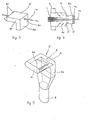
- FIGs. 4 and 5 are perspective views showing a pneumatic duct D' of the present invention.
- a pneumatic tube 6e is formed with a rectangular cross-section and with an opening a 1 which is sized to have a width 1 2 and a height l 1 .
- the aforementioned pneumatic tube 6e is formed at its trailing end with an opening a 2 which has communication with the suction tube 8 and which is formed in a rectangular shape having a width d 2 and a height d 1 .
- a suction portion 8a having the aforementioned opening a 2 has a rectangular cross-section, which is gradually deformed into a circular shape until it is connected with a suction tube 8 which in turn is connected with a vacuum system.
- the openings a 1 and a 2 exert remarkable influences upon the amount of the free or floating fibers which are generated either over the apron 5' or in the gap S between the aprons 5 and 5'.
- the opening a 2 similar to the opening a l of the pneumatic tube 6e having the rectangular cross-section is formed such that it is connected with the suction tube 8.
- the pneumatic tube 6e has its cross-sectional shape made idential to or slightly reduced from the opening a 1 through its whole length- Moreover, the opening a 2 formed in the upper or lower wall of the pneumatic tube 6e may also be shaped identical to or slightly reduced from the aforementioned inlet opening a 1 .
- the Inventors have conducted various experiments concerning the relationship between the openings a 1 and a 2 and have found that the best result can be obtained by making the cross-section of the pneumatic tube 6e to have such a rectangular shape that the width l 2 of the opening a 1 is at least three times as large as the height l 1 , that the width d 2 of the opening a 2 is at least two and half times as large as the height d l , and that relationships of l 2 ⁇ d 2 > 3/4 l 2 hold among the above-identified dimensions.
- Fig. 6 is a view illustrating the action of the pneumatic duct D' according to the present invention.
- the air flows pass along the intermediate yarn lb, as indicated by arrows A 2 , so that the free fibers F' are not instantly wrapped around the aforementioned intermediate yarn lb but gradually wrapped around the surface of said yarn lb.
- the pneumatic tube 6e is formed at its trailing end with the yarn guide hole 6c, through which the yarn lb being false-twisted is guided to and treated by the pneumatic false twisting nozzle 9.
- the opening a 1 has its width l 2 made the closer to its height l 1 , the air flow perpendicular to the yarn lb to be twisted at the apron unit Ls increased the more.
- the opening a 2 has its width d 2 made the closer to its leight d 1 so that its cross-sectional area is gradually ceduced, the air flows resembling the more those Ln the pneumatic duct shown in Fig. 2 are exhibited.
- Fig. 7 shows another embodiment of the present Lnvention.
- the pneumatic tube 6e has its corners rounded the angle into arcuate shapes, and its connecting portion with the suction tube 8a is also formed into an arcuate shape so that the air flow cequired in the present invention may be smoothly generated.
- the openings a 1 and a 2 are made to have a generally rectangular cross-section so that the air flows A 2 shown in Fig. 6 are positively generated above the apron 5' by the iction of the pneumatic duct D' thereby to make it possible to increase the amount of the free fibers F'.
- Fig. 7 shows another embodiment of the present Lnvention.
- the pneumatic tube 6e has its corners rounded the angle into arcuate shapes, and its connecting portion with the suction tube 8a is also formed into an arcuate shape so that the air flow cequired in the present invention may be smoothly generated.
- the openings a 1 and a 2 are made to have a generally rectangular cross-section so that the air flows A 2
- the pneumatic tube 6e has both its side walls formed with triangular walls 6f which project toward the aprons 5 and 5'.
- the directions of the air flow to pass between the aprons 5 and 5' . can be regulated to some extent to increase the amount of the free fibers F'.
- the pneumatic duct. in the aforementioned manner according to the present invention, it is possible to increase the amount of the free fibers to be wrapped around the bundle of main fibers, i.e., the Bundle of core fibers. According to the present invention, therefore, the free fibers can be generated in a sufficient amount, even if the twisting action is weak, so that a spun yarn having a high strength and an excellent feeling can be made.
- Fig. 8 shows an embodiment of the present invention, in which two pneumatic false twisting nozzles are arranged in series.
- a roving yarn 1 or sliver is drafted by the roller draft units 2, 3 and 4.
- the greater part of the fibers are false-twisted by the pneumatic false twisting nozzle 9 but a part of the fibers are twisted into the bundle of false twisted fibers after they have been delivered by the pneumatic tube 6.
- the false twisted fiber bundle is then more densely twisted by the action of a nozzle 9' which is turned in the opposite direction to the nozzle 9.
- the fiber bundle thus prepared is then detwisted, while it is passing through the false twisting nozzle 9', so that the aforementioned fibers thus twisted later are wrapped around the surface of the yarn.
- the yarn thus prepared is nipped by the delivery rollers 10 until it is taken up by the winder 11.
- the pneumatic duct 6 In front of the pneumatic false twisting nozzle 9, there is disposed the pneumatic duct 6 in which air flow is exhausted by the suction tube 8 connected with a vacuum system through the opening 7 formed at the trailing end of the pneumatic tube 8.
- Fig. 9 shows the pneumatic duct and the false twisting nozzle of the prior art. More specifically, Fig. 9 is a sectional side elevation showing the apparatus in which a pnematic duct 17 and a peumatic false twisting nozzle 16 are combined.
- the pneumatic duct 17 is constructed of a cylindrical pneumatic tube 18 and a suction tube 12 which is connected with an opening 19 formed at the trailing end of the former.
- the false twisting nozzle 16 is provided at its center with a yarn guide hole 13 and an injection hole 14 which communicates with the former for swirling the air flow. Compressed air is supplied from a compressed air supply tube 15 and is injected from the aforementioned injection hole 14 thereby to false-twist the yarn passing through the aforementioned hole 13.
- the aforementioned pneumatic duct 17 of the prior art is constructed such that the minimum effective area N of the pneumatic tube 18 is made sufficiently larger than the effective area n of the vacuum opening 19 and such that the fiber bundle which has been delivered from the front rollers 4 is smoothly sucked into the suction tube 10 when the yarn is cut.
- the suction tube during the spinning operation even if the pneumatic tube is opened to satisfy an inequality of N > n between the effective area N of the pneumatic tube and the effective area n of the vacuum opening, and the amount of fibers sucked into the suction tube is generally 0.05 to 0.17 % of the total amount of the derivered fibers so that any special problem is not raised.
- the effective area n of the vacuum opening 19 may be made larger than the minimum effective area of the pneumatic tube 18, as shown in Fig. 10.
- an inlet 18a may have an opening with a horn-like shape.
- Fig. 11 shows another embodiment of the present invention.
- the pneumatic tube 18 has its trailing end portion opened :in its entire circumference, and the opening communicating with the suction tube 12 extends along the entire circumference of the pneumatic tube 18.
- the sectional area n of the opening 19 is made far larger than the minimum effective area N of the pneumatic tube 18.
- the ratio N/n .of the effective areas takes the minimum value 1, and the effects of the pneumatic suction tube .are remarkably high for N/n ⁇ 0.7.
- the ratio N/n it is important in the twisting step to select the conditions under which the free short fibers are sufficiently accelerated in the pneumatic tube 18 and introduced into the yarn guide hole 13 of the pneumatic false twisting nozzle. It is also considered to impart the inertial effects to the free fibers so that the fibers may not be delivered in the pneumatic tube 18 into the aforementioned opening 19.
- the ratio N/n is preferably set at a smaller value. If the suction of the free . fibers is taken into consideration, however, it is necessary that the hole diameter in the N portion be at least 2 mm, namely, that a relationship of N ⁇ ⁇ mm 2 hold.
- the maximum value of the effective area n is different in accordance with the construction of the spinning frame but is not especially limitative.
- the free fibers are delivered around the core fiber bundle which has been twisted. It is, therefore, necessary that the opening communicating with the vacuum system be considered not to obstruct the delivery of the free fibers.
- the suction rate can be reduced to less than 1 %.
- the construction is made to satisfy the following relationships: l 2 /l ⁇ 1.5; and d 2 ⁇ lOp, wherein: letter indicates the width of a bundle . of fibers 20 before it is fed to the pneumatic tube 6, i.e., the width of the fiber bundle before it is reduced by the twisting action of the pneumatic false twisting nozzle; letter l 2 indicated the width of the inlet 111 of a fiber bundle guide passage 110 of the pneumatic tube 6; letter d 2 indicates the width of the opening of a fluid suction port 112 (or the fluid outlet in the case of an aspirator); and letter p indicates the diameter of-an inlet 120 of the fluid twisting nozzle 9.
- the collecting or trapping effect of the peripheral fibers around the fiber bundle in the pneumatic tube is influenced not only by the relationship between the width t of the fiber bundle and the width l 2 of the inlet of the fiber bundle guide passage of the pneumatic tube but also by a kind of balooning action which is established by the rotations of the yarn. Since the intensity of this balooning action of the yarn has a relationship with the diameter p of the inlet of the fluid twisting nozzle, the width d 2 of the fluid suction port or outlet port of the pneumatic tube is deduced from the relationship with the diameter p of the inlet of the fluid twisting nozzle.
- the deteriorating wrapping fibers are reduced so that a spun yarn having a uniform quality and a high strength can be made.
- reference numerals 121, 122 and.123 indicate a twisting portion, a compressed air chamber and an injection hole, respectively.
- the remaining numerals are the same as those which have already been described.
- the aprons are not indispensable, as has been described hereinbefore.
- the generation of the free fibers is not reduced, a spun yarn having a sufficient strength can be obtained even if the number of twists is drastically changed from large to small values.
- the fibers to be sucked into the suction tube are less, the yield can be enhanced. Still moreover, the deteriorated wrapping fibers can be reduced to produce a yarn having a uniform quality.
- the measured values of the strength of the spun yarn produced are tabulated in Table 1. According to the present invention, the strength was increased: for example, the average strength was 2.15 times, and the minimum strength was 8 times as high as those of the yarn which was spun by the use of the pneumatic duct of the prior art:
- Slivers made of polyester staple of single fiber denier 3d were fed to an apparatus similar to that of the Example 1 to produce a spun yarn of 1/6 Nm.
- the spinning conditions were as follows:
- the strength was made higher: for example, the average strength was 1.17 times and the minimum strength was 2.3 times as high as those of the spun yarn which was made by the use of the pneumatic duct of the prior art:
- the spinning operation was conducted by the use of the vortex flow type fine spinning frame which has a three-line draft unit : and a pair of upper and lower aprons having their leading ends opened and which is equipped with a rectangular pneumatic duct and a pneumatic false twisting nozzle downstream of these aprons, as shown in Fig. 1.
- the roving used was a blend of 65 % of polyester of 1.3d x 38 mm and 35 % of combed sliver of American cotton and had 0.55 g/m.
- the spinning operation was conducted under the same conditions as those of the Example 3, and the ratio of fiber sucked was investigated for various N/n ratios.
- the results are tabulated in Table 4, from which it is found that the effect is appreciable for N/n ⁇ 1.0 and high for N/n ⁇ 0.7.
- Considerable effect cannot be obtained for the diameter at the N portion less than 4 mm, and the diameter less than 2 mm is not preferable because the bundling deterioration of the free fibers due to the reduction in the suction flow rate and the clogging with the fibers when the yarn is cut are considered to take place.
- the pneumatic tube was replaced by the tube having horn-shaped fiber bundle guide passage throughout its length, and the same slivers as the aforementioned ones were spun under the same conditions to produce a fasciated spun yarn B.
- the number of fuzz having a length larger than 5 mm, the number of deteriorated wrapping fibers, the number of drawing neps after twice passages through the winder, and the weaving property of blanket when the spun yarns A und B were used as ground yarns were examined.
- the results are tabulated in Table 5.
- the blanket which was woven of the bound spun yarn A had an excellent quality and was found not to be substantially different from the blanket made of a ring spun yarn of 30s/2.
Landscapes
- Engineering & Computer Science (AREA)
- Mechanical Engineering (AREA)
- Textile Engineering (AREA)
- Spinning Or Twisting Of Yarns (AREA)
Applications Claiming Priority (4)
| Application Number | Priority Date | Filing Date | Title |
|---|---|---|---|
| JP100557/81 | 1981-06-30 | ||
| JP10055781A JPS584828A (ja) | 1981-06-30 | 1981-06-30 | 空気渦流精紡機のニユ−マダクト |
| JP105025/81 | 1981-07-07 | ||
| JP10502581A JPS588132A (ja) | 1981-07-07 | 1981-07-07 | 空気渦流精紡機のニユ−マダクト |
Publications (3)
| Publication Number | Publication Date |
|---|---|
| EP0068507A2 true EP0068507A2 (fr) | 1983-01-05 |
| EP0068507A3 EP0068507A3 (en) | 1985-03-06 |
| EP0068507B1 EP0068507B1 (fr) | 1987-09-23 |
Family
ID=26441563
Family Applications (1)
| Application Number | Title | Priority Date | Filing Date |
|---|---|---|---|
| EP82105837A Expired EP0068507B1 (fr) | 1981-06-30 | 1982-06-30 | Machine à fabriquer un filé fascié |
Country Status (5)
| Country | Link |
|---|---|
| US (1) | US4463549A (fr) |
| EP (1) | EP0068507B1 (fr) |
| AU (1) | AU547278B2 (fr) |
| CA (1) | CA1173312A (fr) |
| DE (1) | DE3277380D1 (fr) |
Cited By (2)
| Publication number | Priority date | Publication date | Assignee | Title |
|---|---|---|---|---|
| EP0131170A1 (fr) * | 1983-07-01 | 1985-01-16 | Maschinenfabrik Rieter Ag | Procédé et dispositif de filature par fausse-torsion |
| EP0239387A2 (fr) * | 1986-03-25 | 1987-09-30 | Carding Specialists (Canada) Limited | Procédé et dispositif de modification d'un fil |
Families Citing this family (2)
| Publication number | Priority date | Publication date | Assignee | Title |
|---|---|---|---|---|
| CS8203229A (fr) * | 1982-05-05 | 1984-05-14 | ||
| DE4032940A1 (de) * | 1990-10-17 | 1992-04-23 | Fritz Stahlecker | Vorrichtung zum pneumatischen falschdrallspinnen |
Citations (2)
| Publication number | Priority date | Publication date | Assignee | Title |
|---|---|---|---|---|
| FR1453534A (fr) * | 1965-09-17 | 1966-06-03 | Du Pont | Fil enveloppé, procédé et appareil pour la fabrication de ce fil |
| EP0007483A1 (fr) * | 1978-07-10 | 1980-02-06 | Toray Industries, Inc. | Fil multicolore et procédé pour sa fabrication |
Family Cites Families (12)
| Publication number | Priority date | Publication date | Assignee | Title |
|---|---|---|---|---|
| US3009309A (en) * | 1956-07-16 | 1961-11-21 | Du Pont | Fluid jet twist crimping process |
| US3079746A (en) * | 1961-10-23 | 1963-03-05 | Du Pont | Fasciated yarn, process and apparatus for producing the same |
| US3367095A (en) * | 1967-06-30 | 1968-02-06 | Du Pont | Process and apparatus for making wrapped yarns |
| US3732684A (en) * | 1971-02-23 | 1973-05-15 | Du Pont | Product and process |
| JPS5243256B2 (fr) * | 1973-04-10 | 1977-10-29 | ||
| US4003194A (en) * | 1973-04-10 | 1977-01-18 | Toray Industries, Inc. | Method and apparatus for producing helically wrapped yarn |
| DE2533655C2 (de) * | 1974-10-09 | 1986-11-27 | Toray Industries, Inc., Tokio/Tokyo | Spinnmaschine zur Herstellung von gebündeltem Garn |
| JPS51130334A (en) * | 1975-05-06 | 1976-11-12 | Murata Machinery Ltd | Apparatus for making spun yarns |
| JPS52107349A (en) * | 1976-03-04 | 1977-09-08 | Murata Machinery Ltd | Spun yarn and method of producing same |
| JPS53119334A (en) * | 1977-03-24 | 1978-10-18 | Murata Machinery Ltd | Direct spinning device |
| DE2720519C2 (de) * | 1977-05-06 | 1983-06-23 | Toray Industries, Inc., Tokyo | Verfahren und Vorrichtung zum Starten des Spinnvorganges beim Herstellen eines Garnes aus Stapelfasern |
| DE3023936A1 (de) * | 1979-07-27 | 1981-02-19 | Ernst Dr Fehrer | Vorrichtung zum herstellen eines garnes |
-
1982
- 1982-06-21 US US06/390,682 patent/US4463549A/en not_active Expired - Lifetime
- 1982-06-22 AU AU85109/82A patent/AU547278B2/en not_active Expired
- 1982-06-30 CA CA000406387A patent/CA1173312A/fr not_active Expired
- 1982-06-30 EP EP82105837A patent/EP0068507B1/fr not_active Expired
- 1982-06-30 DE DE8282105837T patent/DE3277380D1/de not_active Expired
Patent Citations (2)
| Publication number | Priority date | Publication date | Assignee | Title |
|---|---|---|---|---|
| FR1453534A (fr) * | 1965-09-17 | 1966-06-03 | Du Pont | Fil enveloppé, procédé et appareil pour la fabrication de ce fil |
| EP0007483A1 (fr) * | 1978-07-10 | 1980-02-06 | Toray Industries, Inc. | Fil multicolore et procédé pour sa fabrication |
Cited By (3)
| Publication number | Priority date | Publication date | Assignee | Title |
|---|---|---|---|---|
| EP0131170A1 (fr) * | 1983-07-01 | 1985-01-16 | Maschinenfabrik Rieter Ag | Procédé et dispositif de filature par fausse-torsion |
| EP0239387A2 (fr) * | 1986-03-25 | 1987-09-30 | Carding Specialists (Canada) Limited | Procédé et dispositif de modification d'un fil |
| EP0239387A3 (fr) * | 1986-03-25 | 1988-01-27 | Carding Specialists (Canada) Limited | Procédé et dispositif de modification d'un fil |
Also Published As
| Publication number | Publication date |
|---|---|
| AU547278B2 (en) | 1985-10-10 |
| AU8510982A (en) | 1983-01-06 |
| CA1173312A (fr) | 1984-08-28 |
| DE3277380D1 (en) | 1987-10-29 |
| EP0068507B1 (fr) | 1987-09-23 |
| US4463549A (en) | 1984-08-07 |
| EP0068507A3 (en) | 1985-03-06 |
Similar Documents
| Publication | Publication Date | Title |
|---|---|---|
| US4124972A (en) | Process and apparatus for producing yarns | |
| US3604194A (en) | Fiber supply method and apparatus in an open-end spinning system utilizing airflow and centrifugal force | |
| US4565063A (en) | Method and apparatus for false twist spinning | |
| US4463549A (en) | Apparatus for making fasciated spun yarn | |
| JPS6320923B2 (fr) | ||
| US4429523A (en) | Process for making fasciated spun yarn | |
| US7328569B2 (en) | Arrangement for producing a spun thread from a staple fiber strand | |
| JPS6018338B2 (ja) | ノズル | |
| US4450678A (en) | Air nozzle utilized for fasciated yarn spinning | |
| JPS6136089B2 (fr) | ||
| JPH0770833A (ja) | 空気紡績装置 | |
| JPH0586510A (ja) | 空気紡績ノズル | |
| JPS643963B2 (fr) | ||
| JPS627289B2 (fr) | ||
| JPS6136090B2 (fr) | ||
| JPH03206139A (ja) | 空気仮撚法による抗菌ポリエステル/羊毛,抗菌ポリエステル/羊毛/ポリエステル混紡糸及びその製造方法 | |
| JPS58208424A (ja) | 結束紡績糸の製造方法および装置 | |
| JPS584828A (ja) | 空気渦流精紡機のニユ−マダクト | |
| JPH0718522A (ja) | 空気紡績装置 | |
| GB1578256A (en) | Method and apparatus for false twisting fibres using fluid | |
| JPH07197330A (ja) | 空気紡績装置 | |
| JPS59137519A (ja) | 吸引管 | |
| JPH01132835A (ja) | 紡績糸の製造装置 | |
| JPS59125914A (ja) | 結束紡績糸の製造方法および装置 | |
| JPH06330413A (ja) | 空気式紡績装置 |
Legal Events
| Date | Code | Title | Description |
|---|---|---|---|
| PUAI | Public reference made under article 153(3) epc to a published international application that has entered the european phase |
Free format text: ORIGINAL CODE: 0009012 |
|
| AK | Designated contracting states |
Designated state(s): CH DE FR GB IT LI |
|
| PUAL | Search report despatched |
Free format text: ORIGINAL CODE: 0009013 |
|
| AK | Designated contracting states |
Designated state(s): CH DE FR GB IT LI |
|
| 17P | Request for examination filed |
Effective date: 19850703 |
|
| 17Q | First examination report despatched |
Effective date: 19860312 |
|
| ITF | It: translation for a ep patent filed | ||
| GRAA | (expected) grant |
Free format text: ORIGINAL CODE: 0009210 |
|
| AK | Designated contracting states |
Kind code of ref document: B1 Designated state(s): CH DE FR GB IT LI |
|
| ET | Fr: translation filed | ||
| REF | Corresponds to: |
Ref document number: 3277380 Country of ref document: DE Date of ref document: 19871029 |
|
| PLBE | No opposition filed within time limit |
Free format text: ORIGINAL CODE: 0009261 |
|
| STAA | Information on the status of an ep patent application or granted ep patent |
Free format text: STATUS: NO OPPOSITION FILED WITHIN TIME LIMIT |
|
| 26N | No opposition filed | ||
| ITTA | It: last paid annual fee | ||
| PGFP | Annual fee paid to national office [announced via postgrant information from national office to epo] |
Ref country code: FR Payment date: 20010611 Year of fee payment: 20 |
|
| PGFP | Annual fee paid to national office [announced via postgrant information from national office to epo] |
Ref country code: DE Payment date: 20010625 Year of fee payment: 20 |
|
| PGFP | Annual fee paid to national office [announced via postgrant information from national office to epo] |
Ref country code: GB Payment date: 20010627 Year of fee payment: 20 |
|
| PGFP | Annual fee paid to national office [announced via postgrant information from national office to epo] |
Ref country code: CH Payment date: 20010628 Year of fee payment: 20 |
|
| REG | Reference to a national code |
Ref country code: GB Ref legal event code: IF02 |
|
| PG25 | Lapsed in a contracting state [announced via postgrant information from national office to epo] |
Ref country code: LI Free format text: LAPSE BECAUSE OF EXPIRATION OF PROTECTION Effective date: 20020629 Ref country code: GB Free format text: LAPSE BECAUSE OF EXPIRATION OF PROTECTION Effective date: 20020629 Ref country code: CH Free format text: LAPSE BECAUSE OF EXPIRATION OF PROTECTION Effective date: 20020629 |
|
| REG | Reference to a national code |
Ref country code: GB Ref legal event code: PE20 Effective date: 20020629 |
|
| REG | Reference to a national code |
Ref country code: CH Ref legal event code: PL |