EP0068069B1 - Cork-screw - Google Patents
Cork-screw Download PDFInfo
- Publication number
- EP0068069B1 EP0068069B1 EP82101417A EP82101417A EP0068069B1 EP 0068069 B1 EP0068069 B1 EP 0068069B1 EP 82101417 A EP82101417 A EP 82101417A EP 82101417 A EP82101417 A EP 82101417A EP 0068069 B1 EP0068069 B1 EP 0068069B1
- Authority
- EP
- European Patent Office
- Prior art keywords
- corkscrew
- bell
- thrust ring
- pot portion
- cork
- Prior art date
- Legal status (The legal status is an assumption and is not a legal conclusion. Google has not performed a legal analysis and makes no representation as to the accuracy of the status listed.)
- Expired
Links
Images

Classifications
-
- B—PERFORMING OPERATIONS; TRANSPORTING
- B67—OPENING, CLOSING OR CLEANING BOTTLES, JARS OR SIMILAR CONTAINERS; LIQUID HANDLING
- B67B—APPLYING CLOSURE MEMBERS TO BOTTLES JARS, OR SIMILAR CONTAINERS; OPENING CLOSED CONTAINERS
- B67B7/00—Hand- or power-operated devices for opening closed containers
- B67B7/02—Hand- or power-operated devices for opening closed containers for removing stoppers
- B67B7/04—Cork-screws
- B67B7/0417—Cork-screws with supporting means for assisting the pulling action
- B67B7/0441—Cork-screws with supporting means for assisting the pulling action whereby the supporting means abut around the whole periphery of the neck of the bottle
Definitions
- the present invention relates to a bell corkscrew according to the preamble of claim 1.
- corkscrews that have a bell-shaped kettle that is placed on the bottle to be opened and into which the cork is pulled as soon as the scraper is screwed in with the handle.
- the bell bowl can have a cylindrical or conical basic shape and can even be formed by a spiral spring.
- a plastic or rubber pressure ring can be attached in the foot of the boiler, which serves for gentle support on the bottle head and z. B. for renewal, cleaning and. Like. Should be quickly replaceable if necessary.
- Means for initially centering and subsequently aligning the scraper that is to say the helix or cutting spindle, are generally not provided. When driving into the cork and / or when pulling it out of the bottle, the scraper is therefore not easily moved parallel to its axis. However, this is an important prerequisite for being able to pull the cork with little effort and as non-destructively as possible.
- DE-C-55 574 discloses a corkscrew of the type mentioned at the outset, which has a bell with a centering projection and diametrically opposed ribs which have rounded inlet edges. Above the bell there is a sleeve in which a compression spring guiding the spindle of the scraper is arranged. After screwing the scraper into the cork, the force of this spring should pull it out of the bottle neck; For this purpose, a special force measuring device is provided. By turning the scraper in the opposite direction, you can unscrew it a bit from the cork.
- a bell corkscrew is known from FR-A-2359785, the spindle of which is guided in a square socket. This has cutouts that mesh with two gear levers linked to the bell. At the lower end a centering lug is provided, into which a plastic pressure ring is fitted.
- the corkscrew has no cork ejection device and does not allow the tip of the scraper to be moved up to the top edge of the pressure ring.
- the bell-shaped vessel holds a pressure ring with an elastic, resilient guide ring sunk in a centering projection.
- This forms a guide element which is as simple as it is effective and which engages over the bottle head, on the end face of which the pressure ring comes to rest during use.
- the scraper therefore attacks the center of the cork and screws into it in the direction of the axis of rotation.
- the pulling movement is practically tilt-free, i. H. with minimal effort and without destroying or damaging the cork.
- the cork ejection device then allows it to be wiped off the scraper without the need for hand contact. For this it is important to specify the dimensioning that the tip of the scraper ends in its fully raised position approximately at the level of the top edge of the pressure ring or above.
- Embodiments of the invention are the subject of claims 2 to 9.
- the measures of claims 2 to 4 are concerned with special embodiments of a cork ejection device which is as simple to manufacture as it is to be handled, the installation on the bottle mouth taking place in a self-guiding manner with good positive locking and the contact surface the pressure ring is designed so that it not only withstands external influences, but is also easy to clean.
- the introduction of the pressure ring in the centering approach of the bell-type bowl and the stable mounting therein is made considerably easier by the features of claims 5 to 8.
- the design according to claim 9 serves to improve handling in a special embodiment.
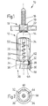
- the corkscrew 10 illustrated in FIG. 1 has a bell 12 with a neck 14 in which a spindle 16 is guided parallel to the axis.
- a toggle 18 with a tilt nut 20 and a handle 22 is used for handling.
- the spindle 16 has a flange 24, which serves as a stop for the movement of the spindle upwards.
- the spindle 16 continues as a scraper 26, i. H. as a cutting spindle or helix, which is intended to be driven into a cork to be pulled.
- the scraper 26 is located between two side webs 28 of the bell 12, the lower end 30 of which forms a boiler 34.
- a centering projection 36 is provided, the upper part of which receives a pressure ring 32 in a form-fitting manner in latching recesses 38.
- the locking recesses 38 can have a radial profile in the form of threads, grooves, beads, projections, grooves and. Like. Have.
- grooves 40a of a radial profile 40 in the centering projection 36 or in the bowl 34 cooperate with a bead 42a of a counter profile 42 on the pressure ring 32.
- teeth 40b of the radial profile are provided for engagement in grooves 42b of the counter profile 42.
- toothings other than those shown, for example serrated or rounded undercuts, bevels, latching lugs and cutouts or the like.
- a shoulder 48 of the pressure ring 32 can be attached to a collar 50 in the centering projection 36 or in the boiler 34 come to rest and if necessary also be firmly attached to it.
- the bearing surface 44 of the pressure ring 32 is preferably just like this itself made of a chemically resistant, resilient material such as soft PVC, polyethylene, rubber or the like, so that there is extensive resistance to the effects of a wide variety of liquids.
- the shape design by means of oblique, arched or undercut ring surfaces or ring surface parts ensures that the pressure ring 32 is tightly connected to the bottle mouth when the corkscrew 10 is used.
- the introduction of the pressure ring 32 into the upper part of the centering projection 36 can be facilitated by a channel 46 (FIG. 5) which is arranged on the outer circumference of the pressure ring 32 and prevents air cushion formation.
- a channel 46 can deviate from the illustrated embodiment and instead of obliquely also parallel to the axis or wound.
- the invention contemplates arranging at least one corresponding channel on the inner circumference of the upper part of centering projection 36 or boiler 34 for air removal between collar 50 and uppermost catch recess 38.
- corkscrew 10 undergoes a considerable improvement in the usability and thus its usefulness thanks to the good shape adaptation of the pressure ring 32 both towards the bottle mouth (i.e. downwards) and towards the inner wall of the centering projection 36 or kettle 34.
- Fig. 1 shows a working position of the bell corkscrew 10, in which the spindle 16 is already fully turned up by means of the knob 18 or the handle 22, so that the flange 24 comes to a stop in the bell 12.
- the scraper 26 is pulled up so far that its tip 56 ends approximately at the level of the upper edge 54 of the pressure ring 32.
- a pulled cork (not shown) would now be held against rotation by the ribs 52, which have more or less gently pressed into the lateral surface of the cork which has been moved up.
- the spindle 16 is moved down again and the cork is automatically pushed off.
- FIG. 3 Yet another embodiment of a cork ejection device on a corkscrew 10 according to the invention is shown schematically in FIG. 3.
- the neck 14 is designed as a wide holder for two articulated levers 68, which are integral with gear sectors 70. The latter mesh with a tooth profile 66 on the spindle 16 so that it can be pulled up by pivoting the lever 68 down.
- the handle 22 is used to screw in the scraper 56, which is integral or rigidly connected to the spindle 16, which in this case can have a bottle opener 72 integral therewith.
- a guide ring 58 which is made of resilient material and is provided with additional recesses 60 (FIG. 2) to facilitate the shape adaptation to different bottle heads, which are grooves, grooves, axially parallel Bores or the like can be formed. This makes handling extremely easy.
Description
Die vorliegende Erfindung betrifft einen Glockenkorkzieher nach dem Oberbegriff des Anspruchs 1.The present invention relates to a bell corkscrew according to the preamble of claim 1.
Für die Handhabung von Korkziehern ist es wichtig, wie gut sie sich ansetzen lassen und auf welche Weise der gezogene Korken von dem Gerät abgenommen werden kann, ohne daß er zerstört wird, was für die Weiter- bzw. Wiederverwendung vorteilhaft ist.For the handling of corkscrews, it is important how well they can be attached and how the pulled cork can be removed from the device without being destroyed, which is advantageous for further or reuse.
Es gibt seit langem Korkzieher, die einen Glockenkessel aufweisen, der auf die zu öffnende Flasche aufgesetzt und in den der Korken hineingezogen wird, sobald man mit dem Griff den Krätzer eindreht. Der Glockenkessel kann eine zylindrische oder konische Grundform haben und sogar von einer Spiralfeder gebildet sein. Auch kann im Fuß des Kessels ein Kunststoff- oder Gummidruckring angebracht sein, der zur schonenden Abstützung auf dem Flaschenkopf dient und z. B. zwecks Erneuerung, Reinigung u. dgl. im Bedarfsfalle rasch auswechselbar sein soll. Mittel zur anfänglichen Zentrierung und nachfolgenden Ausrichtung des Krätzers, also der Wendel bzw. Schneidspindel, sind im allgemeinen nicht vorgesehen. Beim Eintreiben in den Korken und/oder beim Herausziehen aus der Flasche wird der Krätzer daher nicht ohne weiteres parallel zu seiner Achse bewegt. Das ist jedoch eine wichtige Voraussetzung, um den Korken mit kleinem Kraftaufwand und möglichst zerstörungsfrei ziehen zu können.There have long been corkscrews that have a bell-shaped kettle that is placed on the bottle to be opened and into which the cork is pulled as soon as the scraper is screwed in with the handle. The bell bowl can have a cylindrical or conical basic shape and can even be formed by a spiral spring. Also, a plastic or rubber pressure ring can be attached in the foot of the boiler, which serves for gentle support on the bottle head and z. B. for renewal, cleaning and. Like. Should be quickly replaceable if necessary. Means for initially centering and subsequently aligning the scraper, that is to say the helix or cutting spindle, are generally not provided. When driving into the cork and / or when pulling it out of the bottle, the scraper is therefore not easily moved parallel to its axis. However, this is an important prerequisite for being able to pull the cork with little effort and as non-destructively as possible.
In der DE-C-55 574 ist ein Korkzieher der eingangs genannten Art offenbart, der eine Glocke mit Zentrieransatz und sich diametral gegenüberstehenden Rippen aufweist, die gerundete Einlaufkanten haben. Über der Glocke befindet sich eine Hülse, in der eine die Spindel des Krätzers führende Druckfeder angeordnet ist. Nach dem Eindrehen des Krätzers in den Korken soll die Kraft dieser Feder ihn aus dem Flaschenhals herausziehen; hierzu ist eine besondere Kraftmeß-Einrichtung vorgesehen. Durch Drehen des Krätzers in entgegengesetzter Richtung kann man ihn aus dem Korken ein Stück herausschrauben. Dieser muß dennoch von Hand festgehalten werden, weil ein völliges Herausdrehen des Krätzers infolge seiner Länge nicht möglich ist; in ganz hochgedrehter Stellung des Krätzers endet seine Spitze nämlich an der Unterkante des Zentrieransatzes. Da die Feder nicht beliebig zusammendrückbar ist, läßt sich die Krätzerspindel auch nicht voll hochbewegen.DE-C-55 574 discloses a corkscrew of the type mentioned at the outset, which has a bell with a centering projection and diametrically opposed ribs which have rounded inlet edges. Above the bell there is a sleeve in which a compression spring guiding the spindle of the scraper is arranged. After screwing the scraper into the cork, the force of this spring should pull it out of the bottle neck; For this purpose, a special force measuring device is provided. By turning the scraper in the opposite direction, you can unscrew it a bit from the cork. This must still be held by hand, because a complete unscrewing of the scraper is not possible due to its length; when the scraper is in the fully raised position, its tip ends at the lower edge of the centering attachment. Since the spring cannot be compressed at will, the scraper spindle cannot be moved up fully.
Ferner ist aus der FR-A-2359785 ein Glockenkorkzieher bekannt, dessen Spindel in einer Vierkantbuchse geführt ist. Diese hat Aussparungen, die mit zwei an der Glocke angelenkten Zahnradhebeln kämmen. Am unteren Ende ist ein Zentrieransatz vorgesehen, in den ein Druckring aus Kunststoff eingepaßt ist. Der Korkzieher hat jedoch keine Korkausstoß-Einrichtung und erlaubt es auch nicht, die Spitze des Krätzers bis zur Druckring-Oberkante hochzubewegen.Furthermore, a bell corkscrew is known from FR-A-2359785, the spindle of which is guided in a square socket. This has cutouts that mesh with two gear levers linked to the bell. At the lower end a centering lug is provided, into which a plastic pressure ring is fitted. However, the corkscrew has no cork ejection device and does not allow the tip of the scraper to be moved up to the top edge of the pressure ring.
Auch andere frühere Bauformen sehen einen Korkausstoßer vor, namentlich eine konische Glocke, in welcher der Korken beim Hochziehen festgeklemmt wird. Es ist jedoch hierbei im Regelfalle unerläßlich, den Korken von Hand zu halten, da er sich sonst nicht abdrehen läßt und nur auf diese Weise der Korkzieher wiederverwendbar wird. Oft aber ist es recht unangenehm, einen nassen und bisweilen auch verschmutzten oder einen Schimmelansatz tragenden Korken anfassen zu müssen.Other earlier designs also provide a cork ejector, namely a conical bell in which the cork is clamped when it is pulled up. However, it is usually indispensable to hold the cork by hand, otherwise it cannot be unscrewed and the corkscrew can only be reused in this way. However, it is often quite uncomfortable to have to touch a cork that is wet and sometimes also dirty or carries mold.
Es ist ein wichtiges Ziel der Erfindung, diese und weitere Nachteile des Standes der Technik mit einfachen, wirtschaftlichen Mitteln zu überwinden und einen diesbezüglich verbesserten Glockenkorkzieher der genannten Art zu schaffen, der kostengünstig zu fertigen und auch von weniger geschickten Benutzern bequem, gut und sicher zu handhaben ist.It is an important object of the invention to overcome these and other disadvantages of the prior art with simple, economical means and to provide an improved bell corkscrew of the type mentioned, which can be manufactured inexpensively and is also convenient, safe and safe for less skilful users handle is.
Der Grundgedanke der Erfindung ist im kennzeichnenden Teil von Anspruch 1 angegeben. Von besonderer Bedeutung ist hierbei, daß der Glockenkessel einen Druckring mit einem elastisch-nachgiebigen Führungsring versenkt in einem Zentrieransatz haltert. Dies bildet ein ebenso einfaches wie wirksames Führungselement, das den Flaschenkopf übergreift, auf dessen Stirnfläche der Druckring bei der Benutzung zur Anlage kommt. Der Krätzer greift daher mittig am Korken an und schraubt sich in Richtung der Drehachse in ihn hinein. Infolgedessen geht die Ziehbewegung praktisch verkantungsfrei vor sich, d. h. mit geringstem Kraftaufwand und ohne Zerstörung oder Beschädigung des Korkens. Dieser läßt sich daher leicht und glatt aus dem Flaschenhals ziehen. Die Korkausstoß-Einrichtung ermöglicht es, ihn alsdann vom Krätzer abzustreifen, ohne daß eine Handberührung notwendig wäre. Hierfür ist die Bemessungsangabe wichtig, daß die Spitze des Krätzers in seiner ganz hochgedrehten Stellung etwa in Höhe der Druckring-Oberkante oder darüber endet.The basic idea of the invention is specified in the characterizing part of claim 1. It is of particular importance here that the bell-shaped vessel holds a pressure ring with an elastic, resilient guide ring sunk in a centering projection. This forms a guide element which is as simple as it is effective and which engages over the bottle head, on the end face of which the pressure ring comes to rest during use. The scraper therefore attacks the center of the cork and screws into it in the direction of the axis of rotation. As a result, the pulling movement is practically tilt-free, i. H. with minimal effort and without destroying or damaging the cork. This can therefore be easily and smoothly pulled out of the bottle neck. The cork ejection device then allows it to be wiped off the scraper without the need for hand contact. For this it is important to specify the dimensioning that the tip of the scraper ends in its fully raised position approximately at the level of the top edge of the pressure ring or above.
Ausgestaltungen der Erfindung sind Gegenstand der Ansprüche 2 bis 9. Die Maßnahmen der Ansprüche 2 bis 4 befassen sich mit speziellen Ausführungsformen einer Korkausstoß-Einrichtung, die in Fertigung wie Handhabung gleich einfach ist, wobei die Anlage am Flaschenmund selbstführend mit gutem Formschluß erfolgt und die Auflagefläche des Druckringes so gestaltet ist, daß sie nicht nur äußeren Einwirkungen sicher standhält, sondern auch bequem zu reinigen ist. Die Einführung des Druckringes in den Zentrieransatz des Glockenkessels und die stabile Halterung darin wird durch die Merkmale der Ansprüche 5 bis 8 wesentlich erleichtert. Zur Verbesserung der Handhabung bei einer speziellen Ausführungsform dient die Gestaltung gemäß Anspruch 9.Embodiments of the invention are the subject of claims 2 to 9. The measures of claims 2 to 4 are concerned with special embodiments of a cork ejection device which is as simple to manufacture as it is to be handled, the installation on the bottle mouth taking place in a self-guiding manner with good positive locking and the contact surface the pressure ring is designed so that it not only withstands external influences, but is also easy to clean. The introduction of the pressure ring in the centering approach of the bell-type bowl and the stable mounting therein is made considerably easier by the features of claims 5 to 8. The design according to claim 9 serves to improve handling in a special embodiment.
Weitere Merkmale, Einzelheiten und Vorteile der Erfindung ergeben sich aus der folgenden Beschreibung von Ausführungsbeispielen anhand der Zeichnung. Darin zeigen :
- Figur 1 eine Seitenansicht eines erfindungsgemäßen Glockenkorkziehers, teilweise im Schnitt,
- Figur 2 eine Druntersicht auf das untere Ende des Korkziehers von Fig. 1, unter Weglassung sonstiger Teile,
- Figur 3 eine Seitenansicht noch einer weiteren Glockenkorkzieher-Ausführungsform nach der Erfindung,
- Figur 4 eine vergrößerte Teilansicht, teilweise im Schnitt, eines Glockenfußes und
- Figur 5 eine ebensolche Ansicht eines zugehörigen Druckringes.
- FIG. 1 shows a side view of a bell corkscrew according to the invention, partly in section,
- FIG. 2 shows a bottom view of the lower end of the corkscrew from FIG. 1, with the omission of other parts,
- FIG. 3 shows a side view of yet another bell corkscrew embodiment according to the invention,
- Figure 4 is an enlarged partial view, partly in section, of a bell base and
- Figure 5 is a similar view of an associated pressure ring.
Der in Fig. 1 veranschaulichte Korkzieher 10 hat eine Glocke 12 mit einem Hals 14, in dem eine Spindel 16 achsparallel geführt ist. Zur Handhabung dient ein Knebel 18 mit einer Kippmutter 20 und einem Griff 22. Unterhalb des Halses 14 hat die Spindel 16 einen Flansch 24, der als Anschlag für die Bewegung der Spindel nach oben dient. Nach unten setzt sich die Spindel 16 als Krätzer 26 fort, d. h. als Schneidspindel oder Wendel, die zum Eintreiben in einen zu ziehenden Korken bestimmt ist. Der Krätzer 26 befindet sich zwischen zwei Seitenstegen 28 der Glocke 12, deren unteres Ende 30 einen Kessel 34 bildet. In diesem ist ein Zentrieransatz 36 vorgesehen, dessen Oberteil einen Druckring 32 formschlüssig in Rastausnehmungen 38 aufnimmt.The
Die Rastausnehmungen 38 können ein Radialprofil in Form von Gewindegängen, Rillen, Wülsten, Vorsprüngen, Nuten u. dgl. aufweisen. Im Ausführungsbeispiel der Fig. 4 und 5 ist erkennbar, daß Rillen 40a eines Radialprofils 40 im Zentrieransatz 36 bzw. im Kessel 34 mit einem Wulst 42a eines Gegenprofils 42 am Druckring 32 zusammenwirken. Entsprechend sind Zähne 40b des Radialprofils zum Eingriff in Nuten 42b des Gegenprofils 42 vorgesehen. In den Rahmen der Erfindung fallen auch andere als die gezeichneten Zahnungen, beispielsweise gezackte oder gerundete Hinterschneidungen, Schrägen, Rastnasen und -aussparungen o. dgl. Wahlweise oder zusätzlich kann eine Schulter 48 des Druckringes 32 an einem Bund 50 im Zentrieransatz 36 bzw. im Kessel 34 zur Anlage kommen und gegebenenfalls auch stoffschlüssig daran befestigt sein.The
Die Auflagefläche 44 des Druckringes 32 ist bevorzugt ebenso wie dieser selbst aus einem chemisch beständigen, elastisch-nachgiebigen Material wie Weich-PVC, Polyäthylen, Gummi o. dgl., so daß weitestgehende Resistenz gegen Einwirkungen der verschiedensten Flüssigkeiten gegeben ist. Gleichzeitig sichert die Formgestaltung durch schräge, gewölbte oder hinterschnittene Ringflächen bzw. Ringflächenteile, daß der Druckring 32 beim Gebrauch des Korkziehers 10 dicht an den Flaschenmund anschließt.The
Die Einführung des Druckringes 32 in den Oberteil des Zentrieransatzes 36 kann durch einen Kanal 46 (Fig. 5) erleichtert werden, der am Außenumfang des Druckringes 32 angeordnet ist und eine Luftpolsterbildung verhindert. Ein solcher Kanal 46 kann abweichend von der gezeichneten Ausführungsform statt schräg auch achsparallel oder gewunden verlaufen. Auch ist es möglich und erfindungsgemäß vorgesehen, eine Anzahl von Kanälen in den Außenumfang des Druckringes 32 einzuarbeiten, beispielsweise in gekreuzter oder gebogener Form und in regelmäßigen oder unregelmäßigen Umfangs-Abständen. Wahlweise oder zusätzlich zieht die Erfindung in Betracht, wenigstens einen entsprechenden Kanal am Innenumfang des Oberteils von Zentrieransatz 36 bzw. Kessel 34 zur Luftabfuhr zwischen Bund 50 und oberster Rastausnehmung 38 anzuordnen.The introduction of the
Man erkennt, daß der Korkzieher 10 dank guter Formanpassung des Druckringes 32 sowohl zum Flaschenmund hin (d. h. nach unten) als auch zur Innenwand von Zentrieransatz 36 bzw. Kessel 34 hin eine erhebliche Verbesserung der Gebrauchsfähigkeit und damit seines Nutzungswertes erfährt.It can be seen that the
Von besonderer Bedeutung ist die erfindungsgemäß am Korkzieher 10 vorgesehene Korkausstoß-Einrichtung. Dies ist im Ausführungsbeispiel der Fig. 1, 3 und 4 ein Paar sich gegenüberliegender Rippen 52, die nahe der Oberkante 54 des Druckringes 32 bzw. nahe dem Kessel 34 der Glocke 12 beginnend nach oben konisch oder genähert konisch aufsteigen, indem sie zum Hals 14 hin zusammenlaufen. Fig. 1 zeigt eine Arbeitsstellung des Glockenkorkziehers 10, in welcher die Spindel 16 mittels des Knebels 18 bzw. des Griffes 22 bereits ganz hochgedreht ist, so daß der Flansch 24 oben in der Glocke 12 zum Anschlag kommt. Der Krätzer 26 ist hierbei so weit hochgezogen, daß seine Spitze 56 etwa in Höhe der Oberkante 54 des Druckringes 32 endet. Ein (nicht gezeichneter) gezogener Korken würde jetzt von den Rippen 52 gegen Verdrehung gehalten, die sich mehr oder weniger sanft in die Mantelfläche des hochbewegten Korkens eingedrückt haben. Durch Rückdrehen der Handhabungsorgane 18/22 wird die Spindel 16 wieder abwärts bewegt und dabei der Korken selbsttätig abgestoßen.Of particular importance is the cork ejection device provided according to the invention on the
Noch eine andere Ausführungsform einer Korkausstoß-Einrichtung an einem erfindungsgemäßen Korkzieher 10 ist in Fig. 3 schematisiert dargestellt. Hierbei ist der Hals 14 als breite Halterung für zwei angelenkte Hebel 68 gestaltet, die mit Zahnradsektoren 70 einstückig sind. Letztere kämmen mit einem Zahnprofil 66 an der Spindel 16, so daß diese durch Herabschwenken der Hebel 68 hochgezogen werden kann. Zum Eindrehen des mit der Spindel 16 einstückigen bzw. starr verbundenen Krätzers 56 dient der Griff 22, der in diesem Falle einen damit einstückigen Kapselheber 72 aufweisen kann.Yet another embodiment of a cork ejection device on a
Im Zentrieransatz 36 des Kessels 34 sitzt ein Führungsring 58, der aus elastisch-nachgiebigem Material besteht und zur Erleichterung der Formanpassung an verschiedene Flaschenköpfe mit zusätzlichen Aussparungen 60 (Fig. 2) versehen ist, die als Rillen, Riefen, achsparallele Bohrungen o. dgl. ausgebildet sein können. Dadurch wird die Handhabung in höchst bequemer Weise erleichtert.In the centering
Claims (9)
Applications Claiming Priority (2)
| Application Number | Priority Date | Filing Date | Title |
|---|---|---|---|
| DE8118315U | 1981-06-24 | ||
| DE19818118315U DE8118315U1 (en) | 1981-06-24 | 1981-06-24 | BELL CORKSCREW |
Publications (2)
| Publication Number | Publication Date |
|---|---|
| EP0068069A1 EP0068069A1 (en) | 1983-01-05 |
| EP0068069B1 true EP0068069B1 (en) | 1986-02-12 |
Family
ID=6728721
Family Applications (1)
| Application Number | Title | Priority Date | Filing Date |
|---|---|---|---|
| EP82101417A Expired EP0068069B1 (en) | 1981-06-24 | 1982-02-25 | Cork-screw |
Country Status (3)
| Country | Link |
|---|---|
| EP (1) | EP0068069B1 (en) |
| BE (1) | BE905945Q (en) |
| DE (2) | DE8118315U1 (en) |
Families Citing this family (7)
| Publication number | Priority date | Publication date | Assignee | Title |
|---|---|---|---|---|
| US4836060A (en) * | 1988-05-02 | 1989-06-06 | Klefbeck Robert J | Energy efficient cork extractor |
| FR2639629B1 (en) * | 1988-11-30 | 1991-02-22 | Soulas Dominique | MECHANICAL SCREW CORKSCREW |
| GB2246341B (en) * | 1990-07-18 | 1994-03-23 | Tai Lam | Corkscrew |
| FR2669320A1 (en) * | 1990-11-19 | 1992-05-22 | Beauvir Jacques | MECHANICAL CORKSCREW. |
| US5220855A (en) * | 1992-01-10 | 1993-06-22 | Leung Denis T L | Corkscrew |
| IT243711Y1 (en) * | 1998-01-08 | 2002-03-06 | Ghidini Cipriano S A S Di Dieg | STRUCTURE OF CORKSCREW USED WITH STANDARDED MOUTH BOTTLES WITH FLANGED MOUTH |
| GB2504142A (en) * | 2012-07-20 | 2014-01-22 | Julian Brown | A Corkscrew |
Family Cites Families (5)
| Publication number | Priority date | Publication date | Assignee | Title |
|---|---|---|---|---|
| DE60662C (en) * | H. EHRHARDT in Düsseldorf | Innovation in plug pullers | ||
| DE55574C (en) * | E. D. MlDDLEKAUFF und J. S. DUNHAM, Beide in Stockton, San Joaquim County, California, V. St. A | Corkscrew | ||
| DE99374C (en) * | ||||
| FR927558A (en) * | 1946-06-01 | 1947-11-03 | Self-extracting corkscrews | |
| IT1065956B (en) * | 1976-07-28 | 1985-03-04 | Artleva S N C Di Angeli Giulio | TOILET RACK LEVER WITH LEVERS |
-
1981
- 1981-06-24 DE DE19818118315U patent/DE8118315U1/en not_active Expired
-
1982
- 1982-02-25 DE DE8282101417T patent/DE3269033D1/en not_active Expired
- 1982-02-25 EP EP82101417A patent/EP0068069B1/en not_active Expired
-
1986
- 1986-12-17 BE BE2/61124A patent/BE905945Q/en not_active IP Right Cessation
Also Published As
| Publication number | Publication date |
|---|---|
| DE8118315U1 (en) | 1982-12-09 |
| DE3269033D1 (en) | 1986-03-27 |
| BE905945Q (en) | 1987-04-16 |
| EP0068069A1 (en) | 1983-01-05 |
Similar Documents
| Publication | Publication Date | Title |
|---|---|---|
| DE8609398U1 (en) | Self-pulling type corkscrew | |
| CH637902A5 (en) | CORKSCREW. | |
| DE1936174A1 (en) | Device for loosening closure parts from containers | |
| DE1557272B2 (en) | Lipstick case | |
| EP0068069B1 (en) | Cork-screw | |
| DE2461621B2 (en) | THREAD CUTTER ON RING SPINNING AND RING TWISTING MACHINES | |
| EP0167074B1 (en) | Cork-screw | |
| DE60204293T2 (en) | SAFETY SYRINGE | |
| DE7427491U (en) | Lockable container | |
| EP1508527A1 (en) | Closing lid and assembly kit for the manufacture of a tube closure arrangement | |
| DE10115085C1 (en) | Bottle cork extraction device has two separate drives for selective rotation and/or translation of cork extraction tool | |
| DE2926991C2 (en) | Closure drops for medical or pharmaceutical containers | |
| DE3631430C2 (en) | ||
| EP3704032A2 (en) | Container | |
| DE4337305C1 (en) | Device for removal of needle screwed onto extension of syringe body | |
| DE4412913C1 (en) | Blood removal device | |
| DE102009018916B4 (en) | Holder for dental floss | |
| DE4216059C1 (en) | One sided razor with foam container - has neck movable between rest ribs during transport and striker rib for use to allow foam through outlet valve and funnel shaped seat | |
| DE102009029269A1 (en) | Backrest for motor vehicle seat, has backrest support and head support, where snapping bevel is formed in transverse part, and guides cliff spring between clamping position and releasing position | |
| EP1354846B1 (en) | Corkscrew | |
| DE4244574A1 (en) | ||
| DE1948348C (en) | Closure for tubes | |
| DE3818115A1 (en) | LIQUID STORAGE CONTAINERS IN PARTICULAR FOR BODY LIQUIDS | |
| DE7316195U (en) | DOOR PUSH CONNECTION | |
| DE10313432A1 (en) | corkscrew |
Legal Events
| Date | Code | Title | Description |
|---|---|---|---|
| PUAI | Public reference made under article 153(3) epc to a published international application that has entered the european phase |
Free format text: ORIGINAL CODE: 0009012 |
|
| AK | Designated contracting states |
Designated state(s): BE DE FR GB IT NL |
|
| 17P | Request for examination filed |
Effective date: 19830107 |
|
| GRAA | (expected) grant |
Free format text: ORIGINAL CODE: 0009210 |
|
| AK | Designated contracting states |
Designated state(s): BE DE FR GB IT NL |
|
| PG25 | Lapsed in a contracting state [announced via postgrant information from national office to epo] |
Ref country code: BE Effective date: 19860212 |
|
| ITF | It: translation for a ep patent filed |
Owner name: STUDIO JAUMANN |
|
| ET | Fr: translation filed | ||
| REF | Corresponds to: |
Ref document number: 3269033 Country of ref document: DE Date of ref document: 19860327 |
|
| PLBE | No opposition filed within time limit |
Free format text: ORIGINAL CODE: 0009261 |
|
| STAA | Information on the status of an ep patent application or granted ep patent |
Free format text: STATUS: NO OPPOSITION FILED WITHIN TIME LIMIT |
|
| 26N | No opposition filed | ||
| ITTA | It: last paid annual fee | ||
| PGFP | Annual fee paid to national office [announced via postgrant information from national office to epo] |
Ref country code: FR Payment date: 19990124 Year of fee payment: 18 |
|
| PGFP | Annual fee paid to national office [announced via postgrant information from national office to epo] |
Ref country code: NL Payment date: 19990228 Year of fee payment: 18 |
|
| PGFP | Annual fee paid to national office [announced via postgrant information from national office to epo] |
Ref country code: GB Payment date: 20000131 Year of fee payment: 19 |
|
| PGFP | Annual fee paid to national office [announced via postgrant information from national office to epo] |
Ref country code: DE Payment date: 20000307 Year of fee payment: 19 |
|
| PG25 | Lapsed in a contracting state [announced via postgrant information from national office to epo] |
Ref country code: NL Free format text: LAPSE BECAUSE OF NON-PAYMENT OF DUE FEES Effective date: 20000901 |
|
| PG25 | Lapsed in a contracting state [announced via postgrant information from national office to epo] |
Ref country code: FR Free format text: LAPSE BECAUSE OF NON-PAYMENT OF DUE FEES Effective date: 20001031 |
|
| NLV4 | Nl: lapsed or anulled due to non-payment of the annual fee |
Effective date: 20000901 |
|
| REG | Reference to a national code |
Ref country code: FR Ref legal event code: ST |
|
| PG25 | Lapsed in a contracting state [announced via postgrant information from national office to epo] |
Ref country code: GB Free format text: LAPSE BECAUSE OF NON-PAYMENT OF DUE FEES Effective date: 20010225 |
|
| GBPC | Gb: european patent ceased through non-payment of renewal fee |
Effective date: 20010225 |
|
| PG25 | Lapsed in a contracting state [announced via postgrant information from national office to epo] |
Ref country code: DE Free format text: LAPSE BECAUSE OF NON-PAYMENT OF DUE FEES Effective date: 20011201 |