EP0067781B1 - Procédé et dispositif électrique de récupération assistée de pétrole - Google Patents
Procédé et dispositif électrique de récupération assistée de pétrole Download PDFInfo
- Publication number
- EP0067781B1 EP0067781B1 EP82430014A EP82430014A EP0067781B1 EP 0067781 B1 EP0067781 B1 EP 0067781B1 EP 82430014 A EP82430014 A EP 82430014A EP 82430014 A EP82430014 A EP 82430014A EP 0067781 B1 EP0067781 B1 EP 0067781B1
- Authority
- EP
- European Patent Office
- Prior art keywords
- well
- casing
- formation
- oil
- electrode
- Prior art date
- Legal status (The legal status is an assumption and is not a legal conclusion. Google has not performed a legal analysis and makes no representation as to the accuracy of the status listed.)
- Expired
Links
- 238000000034 method Methods 0.000 title claims abstract description 42
- 238000011084 recovery Methods 0.000 title claims abstract description 20
- 230000015572 biosynthetic process Effects 0.000 claims abstract description 59
- 239000007788 liquid Substances 0.000 claims abstract description 10
- 230000001737 promoting effect Effects 0.000 claims abstract description 5
- 230000005684 electric field Effects 0.000 claims description 28
- 238000004519 manufacturing process Methods 0.000 claims description 19
- XLYOFNOQVPJJNP-UHFFFAOYSA-N water Substances O XLYOFNOQVPJJNP-UHFFFAOYSA-N 0.000 claims description 18
- 229910052751 metal Inorganic materials 0.000 claims description 9
- 239000002184 metal Substances 0.000 claims description 9
- 239000011347 resin Substances 0.000 claims description 4
- 229920005989 resin Polymers 0.000 claims description 4
- 241000209499 Lemna Species 0.000 claims 1
- 238000010291 electrical method Methods 0.000 claims 1
- 238000005065 mining Methods 0.000 claims 1
- 239000003129 oil well Substances 0.000 claims 1
- 239000003921 oil Substances 0.000 description 46
- 238000012360 testing method Methods 0.000 description 10
- 230000000694 effects Effects 0.000 description 9
- 238000005370 electroosmosis Methods 0.000 description 8
- 238000005553 drilling Methods 0.000 description 6
- 238000010438 heat treatment Methods 0.000 description 6
- 239000003208 petroleum Substances 0.000 description 6
- 239000000523 sample Substances 0.000 description 6
- 150000003839 salts Chemical class 0.000 description 5
- 239000000243 solution Substances 0.000 description 4
- 239000004020 conductor Substances 0.000 description 3
- 238000005260 corrosion Methods 0.000 description 3
- 230000007797 corrosion Effects 0.000 description 3
- 229930195733 hydrocarbon Natural products 0.000 description 3
- 150000002430 hydrocarbons Chemical class 0.000 description 3
- 239000011810 insulating material Substances 0.000 description 3
- 238000007789 sealing Methods 0.000 description 3
- 238000010408 sweeping Methods 0.000 description 3
- 230000008901 benefit Effects 0.000 description 2
- 238000005868 electrolysis reaction Methods 0.000 description 2
- 238000000605 extraction Methods 0.000 description 2
- 239000011435 rock Substances 0.000 description 2
- 229920006395 saturated elastomer Polymers 0.000 description 2
- 238000012549 training Methods 0.000 description 2
- 229910001152 Bi alloy Inorganic materials 0.000 description 1
- 229910000925 Cd alloy Inorganic materials 0.000 description 1
- 241001480592 Chlorophyllum molybdites Species 0.000 description 1
- 244000000626 Daucus carota Species 0.000 description 1
- 235000002767 Daucus carota Nutrition 0.000 description 1
- 229910000978 Pb alloy Inorganic materials 0.000 description 1
- 229910001245 Sb alloy Inorganic materials 0.000 description 1
- 235000015076 Shorea robusta Nutrition 0.000 description 1
- 244000166071 Shorea robusta Species 0.000 description 1
- 229910001128 Sn alloy Inorganic materials 0.000 description 1
- ATJFFYVFTNAWJD-UHFFFAOYSA-N Tin Chemical compound [Sn] ATJFFYVFTNAWJD-UHFFFAOYSA-N 0.000 description 1
- WATWJIUSRGPENY-UHFFFAOYSA-N antimony atom Chemical compound [Sb] WATWJIUSRGPENY-UHFFFAOYSA-N 0.000 description 1
- 239000010426 asphalt Substances 0.000 description 1
- 230000000712 assembly Effects 0.000 description 1
- 238000000429 assembly Methods 0.000 description 1
- BDOSMKKIYDKNTQ-UHFFFAOYSA-N cadmium atom Chemical compound [Cd] BDOSMKKIYDKNTQ-UHFFFAOYSA-N 0.000 description 1
- 239000003990 capacitor Substances 0.000 description 1
- 239000011248 coating agent Substances 0.000 description 1
- 238000000576 coating method Methods 0.000 description 1
- 230000007423 decrease Effects 0.000 description 1
- 230000002349 favourable effect Effects 0.000 description 1
- 239000011152 fibreglass Substances 0.000 description 1
- 239000012530 fluid Substances 0.000 description 1
- 239000007789 gas Substances 0.000 description 1
- 210000004907 gland Anatomy 0.000 description 1
- 239000003365 glass fiber Substances 0.000 description 1
- 238000002347 injection Methods 0.000 description 1
- 239000007924 injection Substances 0.000 description 1
- 230000009545 invasion Effects 0.000 description 1
- 150000002500 ions Chemical class 0.000 description 1
- 239000006101 laboratory sample Substances 0.000 description 1
- 239000000155 melt Substances 0.000 description 1
- 230000028161 membrane depolarization Effects 0.000 description 1
- 229910001092 metal group alloy Inorganic materials 0.000 description 1
- 238000013508 migration Methods 0.000 description 1
- 230000005012 migration Effects 0.000 description 1
- 239000002480 mineral oil Substances 0.000 description 1
- 235000010446 mineral oil Nutrition 0.000 description 1
- 238000013021 overheating Methods 0.000 description 1
- 239000002245 particle Substances 0.000 description 1
- 230000035515 penetration Effects 0.000 description 1
- 230000010287 polarization Effects 0.000 description 1
- 239000000843 powder Substances 0.000 description 1
- 230000010349 pulsation Effects 0.000 description 1
- 238000005086 pumping Methods 0.000 description 1
- 239000002689 soil Substances 0.000 description 1
- 238000012546 transfer Methods 0.000 description 1
Images


Classifications
-
- E—FIXED CONSTRUCTIONS
- E21—EARTH OR ROCK DRILLING; MINING
- E21B—EARTH OR ROCK DRILLING; OBTAINING OIL, GAS, WATER, SOLUBLE OR MELTABLE MATERIALS OR A SLURRY OF MINERALS FROM WELLS
- E21B43/00—Methods or apparatus for obtaining oil, gas, water, soluble or meltable materials or a slurry of minerals from wells
- E21B43/16—Enhanced recovery methods for obtaining hydrocarbons
- E21B43/24—Enhanced recovery methods for obtaining hydrocarbons using heat, e.g. steam injection
- E21B43/2401—Enhanced recovery methods for obtaining hydrocarbons using heat, e.g. steam injection by means of electricity
-
- E—FIXED CONSTRUCTIONS
- E21—EARTH OR ROCK DRILLING; MINING
- E21B—EARTH OR ROCK DRILLING; OBTAINING OIL, GAS, WATER, SOLUBLE OR MELTABLE MATERIALS OR A SLURRY OF MINERALS FROM WELLS
- E21B36/00—Heating, cooling or insulating arrangements for boreholes or wells, e.g. for use in permafrost zones
- E21B36/003—Insulating arrangements
Definitions
- the subject of the invention is a method and an electrical device for enhanced oil recovery.
- a first category of processes use the heating produced by the Joule effect. These processes require high electrical power to sufficiently heat the deposit and they use alternating current.
- the heating is used for example to carbonize oil shales in the methods described in U.S. Patents 3,106,244, 3,137,347.3,428,125 (H. PARKER).
- Heating is also used to liquefy paraffins, asphalts or bitumen or to reduce viscosity.
- U.S. Patents 1372743 - B. GARDNER
- 3848671 - L. KERN
- 3 149 672 J. ORKISZEWSKI and AI.
- a second category of processes uses electrolysis and the resulting gases to pressurize the deposit or to combine them with hydrocarbons. Such methods are described in U.S. Patents 1784214 - (P. WORK-MAN), 3103975 (A. W. HAUSON), 3724543 and 3782455 (C. W. BELL and AI), 4037655 (N. CAR-PENTER).
- a third category of processes use the action of a unidirectional electric current on a liquid contained in a porous medium similar to capillary tubes to move the liquid by a phenomenon known as electro-osmosis.
- the phenomenon of electro-osmosis is used for example to avoid the invasion of the bottom of a well by the layer of salt water (Coning effect).
- U.S. Patent 3,202,215 (A. STANOWIS) describes a process in which electro-osmosis is used to hold a lens of pure water in the bottom of a well to repel salt water.
- Patent FR 1 268 588 (Institut für du Phyroidle) describes a process according to which a high potential difference, having a defined direction, for example a potential difference between two electrodes located at two points of a deposit, is applied. 1000 and 100,000 Volts.
- US Patent 2,799,641 (TG BELL) describes an enhanced recovery method according to which a potential difference is applied between a first electrode of positive polarity located in the remote formation of a producing well and a second electrode of negative polarity located in the producing well and in direct contact with the reservoir formation.
- the direct voltage is at least 70 Volts and the current intensity of about 10 amps.
- the oil is moved to the cathode.
- the current is interrupted periodically with a frequency of 6 to 30 cycles per minute. It is also possible to use pulses due to the discharges of a capacitor charged under a voltage of the order of 1000 to 3000 volts.
- U.S. Patent 3,417,823 (S. R. FARIS) describes a process in which an anode and a cathode are placed in the same well and the water is moved to the cathode by electro-osmosis.
- US Patent 3,642,066 (William G. GILL) describes an enhanced recovery process in which a cathode is placed in a producing well and an anode in an auxiliary well to move water from the formation to the anode and petroleum towards the cathode. A continuous but pulsed potential difference is applied between the anode and the cathode. The electrodes enter the reservoir formation.
- the objective of the present invention is to provide an assisted recovery method using electrical energy by optimizing the balance sheet of the operation, that is to say the ratio between the additional oil which can be recovered and the electrical energy expended.
- Tests have been carried out in the laboratory on samples of land in the shape of a drill core.
- rock samples were first washed and dried and then saturated with salt water. Oil is then circulated through these samples until water is irreducibly saturated. By difference, we know the oil permeating the rock.
- the amount of additional oil recovered is independent of the direction of production in relation to the direction of application of the electric field, which makes it possible to assume that the electric field has the effect of promoting the ability to move the oil which can then be moved in any direction.
- the electric field would therefore act not to entrain the petroleum towards the cathode or towards the anode, but to break certain bonds which retain petroleum in the formation such as capillary forces or surface tensions and, once these broken bonds, the oil would be made more mobile.
- Tests have been carried out to determine on samples how the energy balance varied, that is to say the quantity of additional oil that can be recovered as a function of the time of application of a determined electric field and therefore of the electrical power consumed.
- the energy balance remains substantially stable during a determined period of application of a determined electrical field, which varies from a few days to a few months, depending on the nature of the formation and the value of the electric field.
- the stability of the balance means that the quantity of additional oil that can be recovered varies in the same direction as the duration of application of the field and that the balance, that is to say the ratio between the quantity of oil recovered and the electrical energy expended remains substantially constant for periods of application of the current not exceeding an upper limit.
- the balance sheet decreases and, whatever the relative cost of oil and electric energy, there is a threshold beyond which the economic balance sheet becomes unfavorable.
- the quantity of oil recovered is therefore substantially proportional to the electrical energy supplied as long as the duration of application of the field remains less than a determined duration.
- Tests have been carried out on samples Ions by applying an alternating electric field having a frequency between a few Hz and a few KHz.
- the present invention relates to methods of enhanced recovery of petroleum contained in a reservoir formation from a well which extends to said formation.
- the methods according to the invention are of the known type in which the oil is displaced by applying a unidirectional potential difference, continuous or pulsed, between two electrodes, at least one of which is placed in said well.
- the duration of the periods of application of the unidirectional electric field is substantially equal to the duration of the rest periods.
- the lower electrode can be moved away, in order to obtain a better distribution of the electric field, within the limits of usable power.
- a lens of a liquid of high resistivity for example pure water.
- the vertical distance between the electrode and the lower end of the conductive casing is at least 40 meters.
- the methods and devices according to the invention make it possible to recover an additional production of oil from a well by spending electrical energy whose cost is lower than the economic value of the additional oil recovered.
- the method and the device according to the invention make it possible to increase the total quantity of oil that the it is possible to extract from a then by alternating periods of application of a unidirectional voltage with periods of electrical rest during which the production can continue.
- the methods and devices according to the invention make it possible to separate the phases of application of the electrical voltage and the phases of production. They make it possible to increase the production of a well by placing the two electrodes in the same then while influencing a large volume of the formation located around the well.
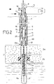
- Figures 1 to 4 are vertical sections of a production well showing examples in which the two electrodes are located in the same well.
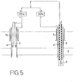
- Figure 5 is a vertical section showing an example of implementation of the method using two wells.
- Figure 1 shows a well 1 which is drilled in the ground and which extends to a reservoir formation 2 containing oil and water.
- the well 1 is, for example, a producing well.
- a seal 11 divides the formation into two parts, an upper part 2a which corresponds to the oil-producing layers at a given time in the exploitation of the deposit and a lower part 2b which corresponds to layers containing water, generally salty.
- the well 1 is equipped with a metal casing 3 (casing) which ends with a shoe 3a located at the roof of the reservoir formation. In this example, it is a so-called overdraft well.
- the well 1 is normally fitted with production tubing 4, the upper end of which is connected to a production pipe 5.
- the casing 4 can be equipped, as shown in FIG. 1, with a pump comprising a piston 6 driven by a rod 7 which passes through a sealing gland 8.
- the well comprises a suspended insulating column 25 having a diameter less than that of the casing, the upper end of which is hooked to a seal 21 fixed to the casing 3.
- This suspended column 25 is made of an insulating material such as a resin reinforced with fiberglass. It crosses formation 2 and has perforations 25a at the crossing of reservoir formation 2a.
- the lower end of the production casing 4 is located above the upper end of the suspended column 25 and above the roof of the reservoir formation 2.
- the lower end of the production casing 4 is fitted with a non-return valve 30.
- a seal 31 is arranged between the valve 30 and the upper end of the suspended column 25 which includes an enlargement 32.
- Production hole 1 normally descends to the wall of reservoir formation 2.
- Figure 1 shows a well that extends below the wall.
- the suspended column 25 also extends below the wall and the lower end of the column 25 is located at a distance of the order of 10 m above the bottom of the well.
- An electrode 9 is placed at the bottom of the well in an electroconductive medium 9a which establishes good electrical contact between the electrode 9 and the surrounding land.
- the electroconductive medium can be salt water coming from layers 2b of the formation. It can also be a non-electrolyzable liquid containing conductive particles, or a metallic powder or a metallic alloy which melts at low temperature, for example an alloy of bismuth, lead, tin, cadmium and antimony.
- the electrode 9 has a great length, greater than several meters, so that the current density at the start of the electrode is reduced, which makes it possible to avoid a temperature rise by Joule effect and to reduce corrosion.
- the electrode 9 is placed at the lower end of a conductive rod 33 which is coated with an insulating sheath 10, which insulates the rod 33 over its entire length, at the with the exception of the lower end which serves as electrode 9.
- the lower end is removable in order to facilitate replacement of the electrode in the event of wear thereof.
- a sealing gasket 34 is placed between the insulating coating 10 and the hanging column 25, at a level equal to or lower than that of the gasket 11.
- the conductive rod 33 is fixed to the lower end of the valve body 30 by a fixing which provides electrical continuity and which has perforations for the passage of oil.
- the production tubing 4 serves as a conductor for energizing the electrode 9.
- the upper end of the casing 4 is connected to a terminal of a source 22 of unidirectional, direct or pulsed voltage, and the upper end of the casing 3 is connected to the other terminal of the source 22.
- the casing 4 is connected to the positive polarity terminal and the electrode 9 is an anode.
- the casing 3 is normally a conductive metallic casing which is in electrical contact with the surrounding land.
- the producer tubing 4 which serves as a conductor is isolated from the conductive casing by an insulating column 14 which delimits with the casing 3 and with the casing 4, two coaxial annular conduits 15 and 16 which communicate by their lower end.
- An insulating liquid for example a mineral oil
- a mineral oil can be circulated between the casing 3 and the casing 4 in order to extract the calories due to the heating of the casing 4, by the Joule effect.
- the upper ends of the annular conduits 15 and 16 are connected respectively to pipes 17 and 18 which constitute the flow and return of an insulating oil circuit which is discharged by a pump 19 and which returns to a tank oil 20.
- the voltage delivered by the source 22 is a high unidirectional voltage, for example between 200 V and several thousand volts.
- the unidirectional voltage can be applied continuously or pulsed with frequencies on the order of several pulses per minute.
- the unidirectional voltage is applied during a first period of long duration, from several days to several months, after which the application of electric current is stopped for a second period of long duration, that is to say a period of several days to several months having for example the same duration as the previous period. During this second period, oil extraction can continue.
- New cycles of application of the current and of electrical rest are then repeated until the production of oil falls below a threshold where the economic value of the oil extracted during a cycle is less than the cost of the electrical energy expended during this same cycle.
- the arrangement according to FIG. 1 makes it possible to have two electrodes in the same well with a distance between electrodes which can be large, for example of the order of several hundred meters, so that the volume of the formation traversed by the lines of electric field strength from anode 9 to the cathode is important.
- the distance between the anode 9 and the lower end of the casing 3 serving as the cathode is greater than 40 meters in order to influence a sufficient formation volume.
- FIG. 1 shows a lens of a slightly conductive liquid 23 which can be injected into the reservoir formation 2 around the well from the casing 4 before the application of the electric voltage.
- the liquid 23 is a liquid with high resistivity, for example pure water. It forms around the well, between the electrode and the lower end of the casing 3, an annular zone of high resistivity, so that it allows greater penetration of the electric current into the formation 2a hence the possibility of improve recovery in a larger volume of formation around a single well.
- FIG. 2 represents an application of the invention in the case of a producing well 1, the equipment of which comprises a perforated casing 3 which crosses the reservoir formation 2 and the shoe 3a of which is located on the wall of the formation.
- the homologous parts are represented by the same references in FIGS. 1 and 2.
- the well is also deepened beyond the wall of the formation to a height of between 20 m and 500 m and it is equipped with a suspended insulating column 25 whose upper end is hooked to the lining 11 which separates the producing layers 2a of the underlying layers 2b.
- the conductive casing 3 is perforated in a part which is located below the perforations and in the layer 2b underlying the producing layer 2a.
- the over-drilling is filled with a ring of insulating material 13 which penetrates into the formation 2b.
- valve housing 30 is electrically insulated from the casing 3 and the sealing gasket 31 is at the same time an insulating gasket. All the other parts of FIG. 2 are analogous to the homologous parts of FIG. 1.
- the electrode 9 is an anode which is connected to the positive terminal of a unidirectional voltage source 22, the casing 3 being connected to the negative terminal of the source 22.
- the anode 9 and the lower end of the casing 3 located above the insulating ring 13 are located at a distance of at least 40 meters, which can reach several hundred meters.
- the direct voltage delivered by the source 22 is between 200 V and 10,000 V.
- the 1 resistance equivalent to the formation volume located between the two electrodes is of the order of a few ohms and the intensity of the current is between a few hundred and a few thousand amps.
- FIG. 3 represents a vertical section of another example of application of the method according to the invention.
- This example represents a production well with a double column.
- a production column 4 and an electrode column which comprises a conductor 33 surrounded by an insulating sleeve 10.
- the metal casing 3 crosses the reservoir formation 2, and has perforations 27 in the crossing thereof.
- the well is drilled below the shoe 3a of the casing to a height of 40 m and more, depending on the applications.
- the anode 9 can be moved by raising or lowering the electrical column, during operation of the method, thus modifying the spacing of the electrodes.
- the drilling below the shoe 3a will take into account at the start of the lowest position of the electrode.
- FIG. 4 represents an assembly similar to that of FIG. 1. The only difference lies in the fact that the metal casing 3 comprises an insulating sleeve 13 intended to electrically insulate the lower part of the casing from the upper part.
- the casing 3 of the producing wells 1 is already in place and generally consists of metal tubes, the casing is sectioned over a height of several meters by over-drilling which is located at a distance of the order of one or several tens of meters above the formation roof.
- the over-perforated space is filled with a ring 13 of an insulating material, for example of a polymerizable resin which penetrates into the surrounding grounds.
- a ring 13 of an insulating material for example of a polymerizable resin which penetrates into the surrounding grounds.
- Another solution if the well is not already equipped with a metal casing, consists in equipping it with a casing comprising, in its lower part, an insulating section of several tens of meters, for example a trongon made of resin reinforced with glass fibers.
- FIG. 5 represents another example of application of the method according to the invention, in which the two electrodes are spaced horizontally by being placed in two wells 1 and 1a.
- the wells 1 and 1a can be producing wells, for example wells equipped with a perforated casing 3, which passes through the reservoir formation 2 and with production tubing 4.
- two DC voltage sources 22a, 22b are used which deliver two different or equal unidirectional voltages.
- the casing 4 and the casing 3 of one of the wells, for example the well 1a, are connected in parallel on the negative terminal of a DC voltage source 22a.
- the casing 4 of the other well carries at its lower end an electrode 9 and it is connected to the positive terminals of the two sources 22a, 22b.
- the assembly of the well 1 is essentially the same as one of the assemblies described in FIGS. 1, 2, 3.
- the casing 3 of the well 1 is also connected to the negative terminal of the source 22b as shown in Figure 5, but this connection could be removed as well as the source 22b.
- one or more wells can be used as cathode and one or more wells as anode.
- This technique lends itself to production by sweeping by means of a pressurized fluid or by pumping, the electrode placed in each well being able to be constituted by the casing, the casing or by an electrode suspended on a cable.
- the latter solution is an extension of the devices according to FIGS. 1, 2 or 3, in which the negative terminal of the source 22b is connected, not only to the casing of a first well containing the anode, but also to the casing of several others producing wells surrounding the first well, so that recovery is improved in all wells.
- All the wells, both those containing the anode and the cathodes, can be producers and the water injection wells for the hydraulic sweep are dissociated from the wells used for injecting the current.
- the cathode consists of the upper part of the conductive metal casing which is the casing normally fitted to the well.
- the anode is a very long anode which is preferably located below the reservoir formation, which may require resuming drilling of a well to deepen it.
- the position of this anode may, in certain cases, be modified, during the operation of the method, in order to vary the spacing of the electrodes, which makes it possible to vary the volume of formation subjected to a determined electric field and to vary the electric field.
- the voltage between electrodes can be varied at the same time as they are moved.
- the distance which separates the anode from the lower end of the cathode is at least 40 meters and can reach several hundred meters, so that the lines of force of the electric field, include a large training volume.
- the rod 33 which electrically connects the body of the valve 30 to the anode 9 can be replaced by a metal chain which is suspended from the valve body and which hangs to the bottom of the well.
- the length of this chain is greater than the height separating the valve body from the bottom of the well, so that part of the chain is coiled at the bottom of the well and replaces the electroconductive medium 9a.
- This solution makes it easy to replace the chain or part of it worn out by electrolytic corrosion.
- the chain is threaded into a sleeve or an insulating sheath 10 with the exception of the coiled part which serves as an electrode
- rod 33 can also be replaced by a conductive cable.
Landscapes
- Geology (AREA)
- Life Sciences & Earth Sciences (AREA)
- Engineering & Computer Science (AREA)
- Mining & Mineral Resources (AREA)
- Environmental & Geological Engineering (AREA)
- Fluid Mechanics (AREA)
- Physics & Mathematics (AREA)
- General Life Sciences & Earth Sciences (AREA)
- Geochemistry & Mineralogy (AREA)
- Production Of Liquid Hydrocarbon Mixture For Refining Petroleum (AREA)
- Lubricants (AREA)
- Fats And Perfumes (AREA)
- Investigation Of Foundation Soil And Reinforcement Of Foundation Soil By Compacting Or Drainage (AREA)
- Water Treatment By Electricity Or Magnetism (AREA)
- Organic Insulating Materials (AREA)
Priority Applications (1)
| Application Number | Priority Date | Filing Date | Title |
|---|---|---|---|
| AT82430014T ATE11805T1 (de) | 1981-06-05 | 1982-05-13 | Verfahren und elektrische einrichtung zur erhoehung der oelgewinnung. |
Applications Claiming Priority (2)
| Application Number | Priority Date | Filing Date | Title |
|---|---|---|---|
| FR8111349A FR2507243A1 (fr) | 1981-06-05 | 1981-06-05 | Procede et dispositif electrique de recuperation assistee de petrole |
| FR8111349 | 1981-06-05 |
Publications (2)
| Publication Number | Publication Date |
|---|---|
| EP0067781A1 EP0067781A1 (fr) | 1982-12-22 |
| EP0067781B1 true EP0067781B1 (fr) | 1985-02-13 |
Family
ID=9259320
Family Applications (1)
| Application Number | Title | Priority Date | Filing Date |
|---|---|---|---|
| EP82430014A Expired EP0067781B1 (fr) | 1981-06-05 | 1982-05-13 | Procédé et dispositif électrique de récupération assistée de pétrole |
Country Status (11)
| Country | Link |
|---|---|
| US (1) | US4466484A (cg-RX-API-DMAC7.html) |
| EP (1) | EP0067781B1 (cg-RX-API-DMAC7.html) |
| JP (1) | JPS587091A (cg-RX-API-DMAC7.html) |
| AT (1) | ATE11805T1 (cg-RX-API-DMAC7.html) |
| AU (1) | AU8437782A (cg-RX-API-DMAC7.html) |
| BR (1) | BR8203291A (cg-RX-API-DMAC7.html) |
| CA (1) | CA1175348A (cg-RX-API-DMAC7.html) |
| DE (1) | DE3262299D1 (cg-RX-API-DMAC7.html) |
| FR (1) | FR2507243A1 (cg-RX-API-DMAC7.html) |
| NO (1) | NO821875L (cg-RX-API-DMAC7.html) |
| OA (1) | OA07118A (cg-RX-API-DMAC7.html) |
Families Citing this family (29)
| Publication number | Priority date | Publication date | Assignee | Title |
|---|---|---|---|---|
| NO161697C (no) * | 1985-12-03 | 1989-09-13 | Ellingsen O & Co | Fremgangsm te for oekning av utvinningsgraden av olj andre flyktige vaesker fra oljereservoar. |
| US4665989A (en) * | 1986-07-01 | 1987-05-19 | Atlantic Richfield Company | Well production start up method |
| US4821798A (en) * | 1987-06-09 | 1989-04-18 | Ors Development Corporation | Heating system for rathole oil well |
| US5101899A (en) * | 1989-12-14 | 1992-04-07 | International Royal & Oil Company | Recovery of petroleum by electro-mechanical vibration |
| US5126037A (en) * | 1990-05-04 | 1992-06-30 | Union Oil Company Of California | Geopreater heating method and apparatus |
| US5323855A (en) * | 1991-05-17 | 1994-06-28 | Evans James O | Well stimulation process and apparatus |
| US5465789A (en) * | 1993-02-17 | 1995-11-14 | Evans; James O. | Apparatus and method of magnetic well stimulation |
| US6328102B1 (en) | 1995-12-01 | 2001-12-11 | John C. Dean | Method and apparatus for piezoelectric transport |
| US5836389A (en) * | 1996-12-09 | 1998-11-17 | Wave Energy Resources | Apparatus and method for increasing production rates of immovable and unswept oil through the use of weak elastic waves |
| US6427774B2 (en) | 2000-02-09 | 2002-08-06 | Conoco Inc. | Process and apparatus for coupled electromagnetic and acoustic stimulation of crude oil reservoirs using pulsed power electrohydraulic and electromagnetic discharge |
| US6227293B1 (en) | 2000-02-09 | 2001-05-08 | Conoco Inc. | Process and apparatus for coupled electromagnetic and acoustic stimulation of crude oil reservoirs using pulsed power electrohydraulic and electromagnetic discharge |
| RU2201501C1 (ru) * | 2001-09-27 | 2003-03-27 | Темерко Александр Викторович | Устройство для воздействия на продуктивный пласт нефтегазоконденсатного месторождения |
| RU2208141C1 (ru) * | 2002-10-28 | 2003-07-10 | Темерко Александр Викторович | Способ разработки нефтегазоконденсатных месторождений |
| RU2239054C1 (ru) * | 2003-04-18 | 2004-10-27 | Институт проблем комплексного освоения недр РАН | Способ разработки залежи газа |
| CA2560223A1 (en) * | 2005-09-20 | 2007-03-20 | Alphonsus Forgeron | Recovery of hydrocarbons using electrical stimulation |
| US7775146B1 (en) | 2006-08-02 | 2010-08-17 | Xtreme Ads Limited | System and method for neutralizing explosives and electronics |
| US7677673B2 (en) * | 2006-09-26 | 2010-03-16 | Hw Advanced Technologies, Inc. | Stimulation and recovery of heavy hydrocarbon fluids |
| US7849919B2 (en) * | 2007-06-22 | 2010-12-14 | Lockheed Martin Corporation | Methods and systems for generating and using plasma conduits |
| DE102010019514B4 (de) * | 2010-05-06 | 2014-07-03 | Tracto-Technik Gmbh & Co. Kg | Erdbohrvorrichtung und Bohrgestänge |
| WO2013042128A2 (en) * | 2010-06-03 | 2013-03-28 | Dass Chanchal | System and method for simultaneous and segregated oil and gas production from multiple zone wells |
| CA2822028A1 (en) * | 2010-12-21 | 2012-06-28 | Chevron U.S.A. Inc. | System and method for enhancing oil recovery from a subterranean reservoir |
| US8683907B1 (en) * | 2011-09-07 | 2014-04-01 | Xtreme Ads Limited | Electrical discharge system and method for neutralizing explosive devices and electronics |
| US9243874B1 (en) | 2011-09-07 | 2016-01-26 | Xtreme Ads Limited | Electrical discharge system and method for neutralizing explosive devices and electronics |
| KR101411642B1 (ko) * | 2012-09-27 | 2014-06-25 | 삼성중공업 주식회사 | 라이저 가이드 장치 |
| WO2015116343A1 (en) * | 2014-01-31 | 2015-08-06 | Harry Bailey Curlett | Method and system for subsurface resource production |
| AU2015255929B2 (en) * | 2014-05-07 | 2019-07-18 | Glen R. Sumner | Submarine or buried piping and pipelines insulated with liquids |
| WO2015176779A1 (en) * | 2014-05-23 | 2015-11-26 | Statoil Petroleum As | Oil and water separation |
| US11352867B2 (en) * | 2020-08-26 | 2022-06-07 | Saudi Arabian Oil Company | Enhanced hydrocarbon recovery with electric current |
| US11883783B2 (en) | 2021-02-26 | 2024-01-30 | Saudi Arabian Oil Company | System and method for electrochemical treatment of aqueous fluid for oilfield applications |
Family Cites Families (21)
| Publication number | Priority date | Publication date | Assignee | Title |
|---|---|---|---|---|
| CA685156A (en) * | 1964-04-28 | G. Bell Thomas | Process of and apparatus for promoting flow of oil from a formation into a well bore | |
| BE460561A (cg-RX-API-DMAC7.html) * | ||||
| US2217857A (en) * | 1937-04-17 | 1940-10-15 | Shell Dev | Process for the removal of mud sheaths |
| US2118669A (en) * | 1937-08-17 | 1938-05-24 | Dow Chemical Co | Method of treating wells |
| US2748868A (en) * | 1954-07-19 | 1956-06-05 | Union Oil Co | Well heater |
| US2799641A (en) * | 1955-04-29 | 1957-07-16 | John H Bruninga Sr | Electrolytically promoting the flow of oil from a well |
| US2982354A (en) * | 1957-04-26 | 1961-05-02 | Thomas D Copeland Jr | Paraffin removing device |
| FR1268588A (fr) * | 1960-06-21 | 1961-08-04 | Inst Francais Du Petrole | Nouveau procédé d'exploitation des gisements de pétrole |
| US3211220A (en) * | 1961-04-17 | 1965-10-12 | Electrofrac Corp | Single well subsurface electrification process |
| US3202215A (en) * | 1962-06-21 | 1965-08-24 | Alphonso F Stanonis | Method of controlling fluid flow |
| US3417823A (en) * | 1966-12-22 | 1968-12-24 | Mobil Oil Corp | Well treating process using electroosmosis |
| US3507330A (en) * | 1968-09-30 | 1970-04-21 | Electrothermic Co | Method and apparatus for secondary recovery of oil |
| US3547192A (en) * | 1969-04-04 | 1970-12-15 | Shell Oil Co | Method of metal coating and electrically heating a subterranean earth formation |
| US3642066A (en) * | 1969-11-13 | 1972-02-15 | Electrothermic Co | Electrical method and apparatus for the recovery of oil |
| US3620300A (en) * | 1970-04-20 | 1971-11-16 | Electrothermic Co | Method and apparatus for electrically heating a subsurface formation |
| US3724543A (en) * | 1971-03-03 | 1973-04-03 | Gen Electric | Electro-thermal process for production of off shore oil through on shore walls |
| US3782465A (en) * | 1971-11-09 | 1974-01-01 | Electro Petroleum | Electro-thermal process for promoting oil recovery |
| US3862662A (en) * | 1973-12-12 | 1975-01-28 | Atlantic Richfield Co | Method and apparatus for electrical heating of hydrocarbonaceous formations |
| US4046194A (en) * | 1976-05-03 | 1977-09-06 | Mobil Oil Corporation | Electrolinking method for improving permeability of hydrocarbon formation |
| US4228854A (en) * | 1979-08-13 | 1980-10-21 | Alberta Research Council | Enhanced oil recovery using electrical means |
| US4382469A (en) * | 1981-03-10 | 1983-05-10 | Electro-Petroleum, Inc. | Method of in situ gasification |
-
1981
- 1981-06-05 FR FR8111349A patent/FR2507243A1/fr active Granted
-
1982
- 1982-05-13 AT AT82430014T patent/ATE11805T1/de not_active IP Right Cessation
- 1982-05-13 DE DE8282430014T patent/DE3262299D1/de not_active Expired
- 1982-05-13 EP EP82430014A patent/EP0067781B1/fr not_active Expired
- 1982-05-28 US US06/383,166 patent/US4466484A/en not_active Expired - Fee Related
- 1982-06-01 AU AU84377/82A patent/AU8437782A/en not_active Abandoned
- 1982-06-03 BR BR8203291A patent/BR8203291A/pt unknown
- 1982-06-04 OA OA57707A patent/OA07118A/xx unknown
- 1982-06-04 NO NO821875A patent/NO821875L/no unknown
- 1982-06-04 CA CA000404535A patent/CA1175348A/en not_active Expired
- 1982-06-04 JP JP57096087A patent/JPS587091A/ja active Pending
Also Published As
| Publication number | Publication date |
|---|---|
| NO821875L (no) | 1982-12-06 |
| EP0067781A1 (fr) | 1982-12-22 |
| DE3262299D1 (en) | 1985-03-28 |
| FR2507243B1 (cg-RX-API-DMAC7.html) | 1983-12-02 |
| US4466484A (en) | 1984-08-21 |
| AU8437782A (en) | 1982-12-09 |
| ATE11805T1 (de) | 1985-02-15 |
| JPS587091A (ja) | 1983-01-14 |
| CA1175348A (en) | 1984-10-02 |
| OA07118A (fr) | 1984-03-31 |
| BR8203291A (pt) | 1983-05-24 |
| FR2507243A1 (fr) | 1982-12-10 |
Similar Documents
| Publication | Publication Date | Title |
|---|---|---|
| EP0067781B1 (fr) | Procédé et dispositif électrique de récupération assistée de pétrole | |
| RU2303692C2 (ru) | Электрохимический способ вторичной добычи нефти путем инициирования в ней окислительно-восстановительных реакций | |
| US4495990A (en) | Apparatus for passing electrical current through an underground formation | |
| CA2858828C (en) | Method for developing deposits and extracting oil and gas from shale formations | |
| CA2049627C (en) | Recovering hydrocarbons from hydrocarbon bearing deposits | |
| US4037655A (en) | Method for secondary recovery of oil | |
| US3724543A (en) | Electro-thermal process for production of off shore oil through on shore walls | |
| US4199025A (en) | Method and apparatus for tertiary recovery of oil | |
| GB1595082A (en) | Method and apparatus for generating gases in a fluid-bearing earth formation | |
| FR2675845A1 (fr) | Methode pour stimuler une zone productrice d'effluents adjacente a une zone aquifere par balayage lateral avec un fluide de deplacement. | |
| US4084639A (en) | Electrode well for electrically heating a subterranean formation | |
| FR2735524A1 (fr) | Methode de recuperation assistee de fluides petroliers dans un gisement souterrain | |
| CA1165360A (en) | Electrode device for electrically heating underground deposits of hydrocarbons | |
| JPH01500530A (ja) | ダウンホール加熱機 | |
| EP0608238B1 (en) | Electro-vac decontamination process | |
| EP0574584B1 (fr) | Procede d'alimentation en gaz d'un utilisateur | |
| CA2691399A1 (fr) | Methode de recuperation d'huile ou de bitume par injection d'un fluide de recuperation et d'un agent de diversion | |
| US3530936A (en) | Electrical method and means for minimizing clogging of a water well | |
| EP1584751B1 (fr) | Procédé de traitement de sol avec utilisation d'au moins un système d'électrodes monopolaires coaxiales et dispositif de mise en oeuvre | |
| CA1196572A (en) | Method of electrically heating underground hydrocarbon deposits | |
| CN107709698B (zh) | 含烃地层的聚焦原位电加热的设备及方法 | |
| CN206694007U (zh) | 油水井电化学靶向调驱和堵水装置 | |
| SU1596112A1 (ru) | Способ создани в пласте канала с минерализованной жидкостью | |
| SU1105604A1 (ru) | Способ освобождени прихваченных в скважине труб | |
| FR2971809A1 (fr) | Procede de production d'hydrocarbures et installation pour la mise en oeuvre |
Legal Events
| Date | Code | Title | Description |
|---|---|---|---|
| PUAI | Public reference made under article 153(3) epc to a published international application that has entered the european phase |
Free format text: ORIGINAL CODE: 0009012 |
|
| AK | Designated contracting states |
Designated state(s): AT DE GB IT NL |
|
| 17P | Request for examination filed |
Effective date: 19830211 |
|
| ITF | It: translation for a ep patent filed | ||
| GRAA | (expected) grant |
Free format text: ORIGINAL CODE: 0009210 |
|
| AK | Designated contracting states |
Designated state(s): AT DE GB IT NL |
|
| REF | Corresponds to: |
Ref document number: 11805 Country of ref document: AT Date of ref document: 19850215 Kind code of ref document: T |
|
| REF | Corresponds to: |
Ref document number: 3262299 Country of ref document: DE Date of ref document: 19850328 |
|
| PGFP | Annual fee paid to national office [announced via postgrant information from national office to epo] |
Ref country code: AT Payment date: 19850419 Year of fee payment: 4 |
|
| PGFP | Annual fee paid to national office [announced via postgrant information from national office to epo] |
Ref country code: NL Payment date: 19850531 Year of fee payment: 4 |
|
| PLBE | No opposition filed within time limit |
Free format text: ORIGINAL CODE: 0009261 |
|
| STAA | Information on the status of an ep patent application or granted ep patent |
Free format text: STATUS: NO OPPOSITION FILED WITHIN TIME LIMIT |
|
| 26N | No opposition filed | ||
| PG25 | Lapsed in a contracting state [announced via postgrant information from national office to epo] |
Ref country code: AT Effective date: 19860513 |
|
| PG25 | Lapsed in a contracting state [announced via postgrant information from national office to epo] |
Ref country code: NL Effective date: 19861201 |
|
| NLV4 | Nl: lapsed or anulled due to non-payment of the annual fee | ||
| GBPC | Gb: european patent ceased through non-payment of renewal fee | ||
| PG25 | Lapsed in a contracting state [announced via postgrant information from national office to epo] |
Ref country code: DE Effective date: 19870203 |
|
| PG25 | Lapsed in a contracting state [announced via postgrant information from national office to epo] |
Ref country code: GB Effective date: 19881121 |