EP0067757B1 - In eine Anschlussleiste einer Sammelschiene steckbarer elektronischer Modul - Google Patents
In eine Anschlussleiste einer Sammelschiene steckbarer elektronischer Modul Download PDFInfo
- Publication number
- EP0067757B1 EP0067757B1 EP19820401002 EP82401002A EP0067757B1 EP 0067757 B1 EP0067757 B1 EP 0067757B1 EP 19820401002 EP19820401002 EP 19820401002 EP 82401002 A EP82401002 A EP 82401002A EP 0067757 B1 EP0067757 B1 EP 0067757B1
- Authority
- EP
- European Patent Office
- Prior art keywords
- card
- connector
- electronic module
- connection
- housing
- Prior art date
- Legal status (The legal status is an assumption and is not a legal conclusion. Google has not performed a legal analysis and makes no representation as to the accuracy of the status listed.)
- Expired
Links
Images

Classifications
-
- H—ELECTRICITY
- H05—ELECTRIC TECHNIQUES NOT OTHERWISE PROVIDED FOR
- H05K—PRINTED CIRCUITS; CASINGS OR CONSTRUCTIONAL DETAILS OF ELECTRIC APPARATUS; MANUFACTURE OF ASSEMBLAGES OF ELECTRICAL COMPONENTS
- H05K7/00—Constructional details common to different types of electric apparatus
- H05K7/14—Mounting supporting structure in casing or on frame or rack
- H05K7/1462—Mounting supporting structure in casing or on frame or rack for programmable logic controllers [PLC] for automation or industrial process control
- H05K7/1468—Mechanical features of input/output (I/O) modules
-
- H—ELECTRICITY
- H05—ELECTRIC TECHNIQUES NOT OTHERWISE PROVIDED FOR
- H05K—PRINTED CIRCUITS; CASINGS OR CONSTRUCTIONAL DETAILS OF ELECTRIC APPARATUS; MANUFACTURE OF ASSEMBLAGES OF ELECTRICAL COMPONENTS
- H05K7/00—Constructional details common to different types of electric apparatus
- H05K7/14—Mounting supporting structure in casing or on frame or rack
- H05K7/1462—Mounting supporting structure in casing or on frame or rack for programmable logic controllers [PLC] for automation or industrial process control
- H05K7/1475—Bus assemblies for establishing communication between PLC modules
- H05K7/1477—Bus assemblies for establishing communication between PLC modules including backplanes
Definitions
- the housing of the electronic module comprises an individual metal sheath of parallelepipedal shape secured to the base by fixing screws. Correct insertion of the card requires means for centering the sheath relative to the fixed connector of the bus.
- FR-A-2412224 describes a connection device comprising a printed circuit board provided with male contacts and mounted in a support system constituted by two slides, a front connector and a rear connector.
- the invention aims to facilitate the racking of the card on the bus and the terminal connector.
- the housing of the electronic module is made up of two separable elementary parts of conjugate forms serving respectively as a support, one at the terminal connector, the other at the card, the assembly of the two parts being effected during the electrical connection of the card with a terminal block connector strip.
- the terminal connector is arranged in the vicinity of the front face of the housing opposite the bus connector and the connection strip cooperates with contact tabs of the card during the assembly of the two parts and plugging the module into the bus connector.
- connection strip is equipped with a plurality of insertion contacts oriented towards the inside of the housing.
- An external connection terminal support is juxtaposed with the connection strip projecting towards the outside of the housing.
- a chute is arranged on one of the parts of the housing for housing the wiring connected to the support for external connection terminals.
- the module housing is provided with an opening allowing the insertion of a test bar on an auxiliary test connector of the card.
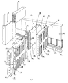
- a programmable automation device comprises a base 10 constituted by a support profile secured either to a panel (not shown), or to a rack 12 with side flanges 14.
- a connection card 16 or bus circuit formed by a printed circuit board on which are staggered at regular intervals a plurality of fixed connectors 18 electrically connected to predetermined connection points of the bus 16.
- Each connector 18 of the bus 16 cooperates by plugging in with a conjugate connection system or connector 20 secured to a card 21 of a plug-in electronic module 22.
- the bus 16 has as many fixed connectors 18 as there are modules 22, and the connectors 18, 20 are provided with contact elements with female-male or male-female insertion.
- the base 10 also serves as rear shielding for the bus 16.
- the electronic components are mounted on the cards 21 of the plug-in modules 22, and the bus 16 is devoid of components ensuring the interconnection of the cards 21 with printed circuits.
- the card 21 of each module 22 is housed in a metal box 24 of parallelepiped shape, one of the side faces of which is provided with lights 26 for the evacuation of the heat generated inside the box 24. This the latter also serves as mechanical protection, and electromagnetic shielding of the card.
- each input and output module 22 of the automaton is formed by the assembly of two elementary parts 28, 30 fixed to one another when the card 21 is inserted into the corresponding connector 18 of the bus 16.
- One of the parts has an L-shaped profile fixed by its rear flank 32 to the base 10, the other flank 34 at an angle constituting one of the side faces of the housing 24.
- the rear flank 32 has a window (not shown) or is partially cut out to allow access to the connector 18 of the bus 16.
- the front front part of the sidewall 34 carries an auxiliary terminal connector 38 intended for the external electrical connection of the industrial installation with the card 21 , in particular for the acquisition of data and the transmission of orders prepared by the control unit depending on whether it is an input or output module, respectively.
- terminal connector will denote below a connector equipped with terminals.
- the terminal connector 38 of each module 22 extends vertically in the height direction of the housing 24 and includes a connection strip 40 juxtaposed to a support 41 of external connection terminals.
- the connection strip 40 projects towards the inside of the housing 24 and is fitted with female contacts 42 with insertion for connection with the printed circuit of the card 21.
- the support 41 of external connection terminals projects towards the outside of the sidewall 34 and comprises a plurality of lateral terminals 44 capable of receiving the cables 45 for external connection.
- the wiring is housed in a vertical chute 46 arranged along the external face of the sidewall 34.
- the terminals 44 of the support 41 of external connection terminals can be of any type, in particular screw, pin, clip or clamping spring shaped in a cage.
- the other part 30 of the housing 24 has the front face 47 and a sheath 48 for supporting the card 21.
- the sheath 48 is an extruded or molded U-shaped profile whose small opposite faces 50, 52 opposite upper and lower are provided with internal grooves 54 for positioning and guiding the card 21.
- the lateral face of the sheath 48 serves for the evacuation of the heat by the openings 26.
- each card 21 is equipped with a plurality of plug-in tabs 56 with male contacts coming into engagement with the corresponding female contacts 42 of the connection strip 40 during insertion. from the electronic card 21 into the appropriate connector 18 of the bus 16.
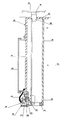
- a test bar 58 can be associated with each module 22, the upper face 50 of the housing 24 is provided with an opening 60 allowing the vertical connection of the test bar 58 to an auxiliary test connector of the card 21. In the plugged-in position, the test bar 58 is superimposed on the module 22, the size of the housing 24 in the width and depth direction corresponds substantially to that of the test bar 58.
- the bus circuit (not shown) is located at the rear of the base 10, or can be integrated into the latter. Rectangular openings 62 are provided in the base 10 for the passage of the connectors 18 of the bus.
- the part 28 of the housing 24 of each module 22 has a U-folded structure fixed to the base 10 by fixing means introduced into the ears 64.
- the terminal connector 38 is carried by the part 28 and extends vertically between the lateral wings 66, 68 upper and lower of the U in the vicinity of the front face 47.
- the upper wing 66 of the U has an opening 60 for the insertion of the test bar 58 on the test connector of the card 21.
- the other part 30 of the box 24 includes the card 21 secured to a parallel plate 70 offset in the width direction.
- the assembly of card 21 and associated plate 70 of part 30 slides from the front face into grooves 72 arranged in the wings 66, 68 of part 28 of the housing 24.
- the contact tabs 56 of the card 21 of each module 22 cooperate by plugging in with the terminal connector 38, and the rear connector 20 of the card 21 is inserted in the corresponding connector 18 of the bus.
Landscapes
- Engineering & Computer Science (AREA)
- Automation & Control Theory (AREA)
- Microelectronics & Electronic Packaging (AREA)
- Coupling Device And Connection With Printed Circuit (AREA)
Claims (8)
Applications Claiming Priority (2)
| Application Number | Priority Date | Filing Date | Title |
|---|---|---|---|
| FR8111124 | 1981-06-03 | ||
| FR8111124A FR2507395A1 (fr) | 1981-06-03 | 1981-06-03 | Module electronique enfichable dans un connecteur de bus |
Publications (2)
| Publication Number | Publication Date |
|---|---|
| EP0067757A1 EP0067757A1 (de) | 1982-12-22 |
| EP0067757B1 true EP0067757B1 (de) | 1985-10-16 |
Family
ID=9259212
Family Applications (1)
| Application Number | Title | Priority Date | Filing Date |
|---|---|---|---|
| EP19820401002 Expired EP0067757B1 (de) | 1981-06-03 | 1982-06-01 | In eine Anschlussleiste einer Sammelschiene steckbarer elektronischer Modul |
Country Status (4)
| Country | Link |
|---|---|
| EP (1) | EP0067757B1 (de) |
| CA (1) | CA1186388A (de) |
| DE (1) | DE3266907D1 (de) |
| FR (1) | FR2507395A1 (de) |
Cited By (4)
| Publication number | Priority date | Publication date | Assignee | Title |
|---|---|---|---|---|
| DE3412593A1 (de) * | 1984-04-04 | 1985-10-17 | Klöckner-Moeller Elektrizitäts GmbH, 5300 Bonn | Gekapselte baugruppe fuer elektronische baueinheiten |
| DE3633209A1 (de) * | 1986-09-30 | 1988-03-31 | Siemens Ag | Aufnahmevorrichtung fuer geraeteeinheiten der elektrischen nachrichtentechnik |
| DE3633800A1 (de) * | 1986-10-04 | 1988-04-14 | Endress Hauser Gmbh Co | Geraet zum empfangen, aufbereiten, verwerten und weiterleiten elektrischer signale |
| DE19841999A1 (de) * | 1998-09-04 | 2000-03-23 | Siemens Ag | Elektrisches Gerät |
Families Citing this family (12)
| Publication number | Priority date | Publication date | Assignee | Title |
|---|---|---|---|---|
| DE3313113A1 (de) * | 1983-04-12 | 1984-10-18 | Industrieelektronik Dr. Ing. Walter Klaschka GmbH & Co, 7533 Tiefenbronn | Baugruppentraeger fuer elektrische steckkarten |
| FR2544556B1 (fr) * | 1983-04-15 | 1985-07-05 | Telemecanique Electrique | Dispositif entree/sortie pour automate programmable, gamme de tels dispositifs et procede pour realiser leur bornier |
| FR2544555B1 (fr) * | 1983-04-15 | 1985-10-18 | Telemecanique Electrique | Amenagement d'automate programmable et procede pour sa realisation |
| DE3418947A1 (de) * | 1984-05-22 | 1985-11-28 | Klöckner-Moeller Elektrizitäts GmbH, 5300 Bonn | Vorrichtung zum adressieren der ein- und ausgaenge bei elektronischen baueinheiten |
| JPS6118003A (ja) * | 1984-07-04 | 1986-01-25 | Hitachi Ltd | 制御装置 |
| FR2579835B1 (fr) * | 1985-04-02 | 1987-06-19 | Cgee Alsthom Direction Red | Module electronique enfichable sur un connecteur bus |
| DE3635971A1 (de) * | 1986-10-22 | 1988-04-28 | Siemens Ag | Baugruppentraeger fuer steckbare baugruppen |
| EP0419694B1 (de) * | 1989-09-25 | 1994-07-13 | Siemens Aktiengesellschaft | Baugruppen zum Anschluss an einen Baugruppenträger |
| US5218518A (en) * | 1989-09-25 | 1993-06-08 | Siemens Aktiengesellschaft | Rack mountable box shaped module with conical positioning elements |
| US5157590A (en) * | 1991-04-19 | 1992-10-20 | Square D Company | Mounting bracket for a programmable logic controller control module |
| DE69227690T2 (de) * | 1991-08-09 | 1999-05-20 | Tandem Computers Inc., Cupertino, Calif. | Elektronische baugruppe mit verbesserter erdung |
| EP0536560B1 (de) * | 1991-10-11 | 1996-06-12 | Asea Brown Boveri Ag | Ein- und/oder Ausgabegerät für Prozessdaten |
Family Cites Families (4)
| Publication number | Priority date | Publication date | Assignee | Title |
|---|---|---|---|---|
| US3631299A (en) * | 1970-05-21 | 1971-12-28 | Square D Co | Printed circuit board module and support with circuit board supporting posts |
| US3729657A (en) * | 1971-07-15 | 1973-04-24 | Allen Bradley Co | Coded circuit mounting device with cover |
| FR2207404B1 (de) * | 1972-11-20 | 1976-04-23 | Merlin Gerin | |
| FR2412224A1 (fr) * | 1977-12-16 | 1979-07-13 | Alsthom Cgee | Dispositif de connexion avant pour une carte de circuit imprime |
-
1981
- 1981-06-03 FR FR8111124A patent/FR2507395A1/fr active Granted
-
1982
- 1982-06-01 EP EP19820401002 patent/EP0067757B1/de not_active Expired
- 1982-06-01 DE DE8282401002T patent/DE3266907D1/de not_active Expired
- 1982-06-03 CA CA000404400A patent/CA1186388A/fr not_active Expired
Cited By (4)
| Publication number | Priority date | Publication date | Assignee | Title |
|---|---|---|---|---|
| DE3412593A1 (de) * | 1984-04-04 | 1985-10-17 | Klöckner-Moeller Elektrizitäts GmbH, 5300 Bonn | Gekapselte baugruppe fuer elektronische baueinheiten |
| DE3633209A1 (de) * | 1986-09-30 | 1988-03-31 | Siemens Ag | Aufnahmevorrichtung fuer geraeteeinheiten der elektrischen nachrichtentechnik |
| DE3633800A1 (de) * | 1986-10-04 | 1988-04-14 | Endress Hauser Gmbh Co | Geraet zum empfangen, aufbereiten, verwerten und weiterleiten elektrischer signale |
| DE19841999A1 (de) * | 1998-09-04 | 2000-03-23 | Siemens Ag | Elektrisches Gerät |
Also Published As
| Publication number | Publication date |
|---|---|
| CA1186388A (fr) | 1985-04-30 |
| EP0067757A1 (de) | 1982-12-22 |
| DE3266907D1 (en) | 1985-11-21 |
| FR2507395B1 (de) | 1984-02-10 |
| FR2507395A1 (fr) | 1982-12-10 |
Similar Documents
| Publication | Publication Date | Title |
|---|---|---|
| EP0067757B1 (de) | In eine Anschlussleiste einer Sammelschiene steckbarer elektronischer Modul | |
| US4822303A (en) | Electrical connector | |
| CA2017173C (en) | Connector bank with overvoltage surge protection | |
| KR102131071B1 (ko) | 리셉터클 캐리어들을 갖는 커넥터 어셈블리 | |
| CN1211348A (zh) | 屏蔽式接线盒 | |
| US5049092A (en) | Connector assembly for electrical components | |
| US6241561B1 (en) | Terminal block arrangement for an electrical system | |
| FR2900307A3 (fr) | Boitier pour composants electroniques | |
| FR2508721A1 (fr) | Dispositif adaptateur pour connecteur electrique femelle | |
| US6109959A (en) | Electrical socket device | |
| CA2040286C (en) | Connector attachment component | |
| EP0944145A1 (de) | Niederspannungsverteiler | |
| US10232810B2 (en) | Electrical connection box | |
| FR2631747A1 (fr) | Connecteur electrique et ensemble combine incluant un tel connecteur electrique et une plaquette a circuits imprimes | |
| US5653018A (en) | Method for the manufacture of an electric appliance | |
| US5879167A (en) | Contact element for anticipatory earthing | |
| US7092244B2 (en) | Connection or distributing device for electrical installation equipment | |
| EP0208565A1 (de) | Gestell mit schnappbaren Steckverbindungsklammern für einen mehrpoligen trennbaren Schalter | |
| US5567182A (en) | Ultra multiple connector | |
| JP7195843B2 (ja) | 分電盤 | |
| KR101842006B1 (ko) | 최적화된 커넥터 배치를 갖는 장치 | |
| US20010039132A1 (en) | Connecting element for connecting cable shields | |
| FR2491716A1 (fr) | Connecteurs borniers encliquetables pour tiroir a cartes electroniques | |
| EP0860901A1 (de) | Gehäuse für elektrischen Gerät und elektrische Vorrichtung mit einem solchen Gehäuse | |
| GB2037494A (en) | Improvements Relating to Electric Terminal Members |
Legal Events
| Date | Code | Title | Description |
|---|---|---|---|
| PUAI | Public reference made under article 153(3) epc to a published international application that has entered the european phase |
Free format text: ORIGINAL CODE: 0009012 |
|
| AK | Designated contracting states |
Designated state(s): BE CH DE GB IT LI NL SE |
|
| 17P | Request for examination filed |
Effective date: 19830707 |
|
| R17P | Request for examination filed (corrected) |
Effective date: 19830622 |
|
| ITF | It: translation for a ep patent filed | ||
| GRAA | (expected) grant |
Free format text: ORIGINAL CODE: 0009210 |
|
| AK | Designated contracting states |
Designated state(s): BE CH DE GB IT LI NL SE |
|
| REF | Corresponds to: |
Ref document number: 3266907 Country of ref document: DE Date of ref document: 19851121 |
|
| PLBE | No opposition filed within time limit |
Free format text: ORIGINAL CODE: 0009261 |
|
| STAA | Information on the status of an ep patent application or granted ep patent |
Free format text: STATUS: NO OPPOSITION FILED WITHIN TIME LIMIT |
|
| 26N | No opposition filed | ||
| PGFP | Annual fee paid to national office [announced via postgrant information from national office to epo] |
Ref country code: GB Payment date: 19890531 Year of fee payment: 8 |
|
| PGFP | Annual fee paid to national office [announced via postgrant information from national office to epo] |
Ref country code: SE Payment date: 19890612 Year of fee payment: 8 |
|
| PGFP | Annual fee paid to national office [announced via postgrant information from national office to epo] |
Ref country code: CH Payment date: 19890614 Year of fee payment: 8 |
|
| PGFP | Annual fee paid to national office [announced via postgrant information from national office to epo] |
Ref country code: BE Payment date: 19890629 Year of fee payment: 8 |
|
| ITTA | It: last paid annual fee | ||
| PGFP | Annual fee paid to national office [announced via postgrant information from national office to epo] |
Ref country code: NL Payment date: 19890630 Year of fee payment: 8 |
|
| PGFP | Annual fee paid to national office [announced via postgrant information from national office to epo] |
Ref country code: DE Payment date: 19890831 Year of fee payment: 8 |
|
| PG25 | Lapsed in a contracting state [announced via postgrant information from national office to epo] |
Ref country code: GB Effective date: 19900601 |
|
| PG25 | Lapsed in a contracting state [announced via postgrant information from national office to epo] |
Ref country code: SE Effective date: 19900602 |
|
| PG25 | Lapsed in a contracting state [announced via postgrant information from national office to epo] |
Ref country code: LI Effective date: 19900630 Ref country code: CH Effective date: 19900630 Ref country code: BE Effective date: 19900630 |
|
| BERE | Be: lapsed |
Owner name: MERLIN GERIN Effective date: 19900630 |
|
| PG25 | Lapsed in a contracting state [announced via postgrant information from national office to epo] |
Ref country code: NL Effective date: 19910101 |
|
| GBPC | Gb: european patent ceased through non-payment of renewal fee | ||
| NLV4 | Nl: lapsed or anulled due to non-payment of the annual fee | ||
| REG | Reference to a national code |
Ref country code: CH Ref legal event code: PL |
|
| PG25 | Lapsed in a contracting state [announced via postgrant information from national office to epo] |
Ref country code: DE Effective date: 19910403 |
|
| EUG | Se: european patent has lapsed |
Ref document number: 82401002.9 Effective date: 19910206 |