EP0066998B1 - Display system - Google Patents
Display system Download PDFInfo
- Publication number
- EP0066998B1 EP0066998B1 EP82302630A EP82302630A EP0066998B1 EP 0066998 B1 EP0066998 B1 EP 0066998B1 EP 82302630 A EP82302630 A EP 82302630A EP 82302630 A EP82302630 A EP 82302630A EP 0066998 B1 EP0066998 B1 EP 0066998B1
- Authority
- EP
- European Patent Office
- Prior art keywords
- screen
- display system
- light
- observer
- scattering
- Prior art date
- Legal status (The legal status is an assumption and is not a legal conclusion. Google has not performed a legal analysis and makes no representation as to the accuracy of the status listed.)
- Expired
Links
Images

Classifications
-
- G—PHYSICS
- G09—EDUCATION; CRYPTOGRAPHY; DISPLAY; ADVERTISING; SEALS
- G09G—ARRANGEMENTS OR CIRCUITS FOR CONTROL OF INDICATING DEVICES USING STATIC MEANS TO PRESENT VARIABLE INFORMATION
- G09G1/00—Control arrangements or circuits, of interest only in connection with cathode-ray tube indicators; General aspects or details, e.g. selection emphasis on particular characters, dashed line or dotted line generation; Preprocessing of data
- G09G1/06—Control arrangements or circuits, of interest only in connection with cathode-ray tube indicators; General aspects or details, e.g. selection emphasis on particular characters, dashed line or dotted line generation; Preprocessing of data using single beam tubes, e.g. three-dimensional or perspective representation, rotation or translation of display pattern, hidden lines, shadows
-
- G—PHYSICS
- G06—COMPUTING OR CALCULATING; COUNTING
- G06T—IMAGE DATA PROCESSING OR GENERATION, IN GENERAL
- G06T15/00—Three-dimensional [3D] image rendering
- G06T15/10—Geometric effects
- G06T15/40—Hidden part removal
- G06T15/405—Hidden part removal using Z-buffer
-
- G—PHYSICS
- G09—EDUCATION; CRYPTOGRAPHY; DISPLAY; ADVERTISING; SEALS
- G09B—EDUCATIONAL OR DEMONSTRATION APPLIANCES; APPLIANCES FOR TEACHING, OR COMMUNICATING WITH, THE BLIND, DEAF OR MUTE; MODELS; PLANETARIA; GLOBES; MAPS; DIAGRAMS
- G09B9/00—Simulators for teaching or training purposes
- G09B9/02—Simulators for teaching or training purposes for teaching control of vehicles or other craft
- G09B9/08—Simulators for teaching or training purposes for teaching control of vehicles or other craft for teaching control of aircraft, e.g. Link trainer
- G09B9/30—Simulation of view from aircraft
- G09B9/301—Simulation of view from aircraft by computer-processed or -generated image
- G09B9/302—Simulation of view from aircraft by computer-processed or -generated image the image being transformed by computer processing, e.g. updating the image to correspond to the changing point of view
-
- G—PHYSICS
- G09—EDUCATION; CRYPTOGRAPHY; DISPLAY; ADVERTISING; SEALS
- G09B—EDUCATIONAL OR DEMONSTRATION APPLIANCES; APPLIANCES FOR TEACHING, OR COMMUNICATING WITH, THE BLIND, DEAF OR MUTE; MODELS; PLANETARIA; GLOBES; MAPS; DIAGRAMS
- G09B9/00—Simulators for teaching or training purposes
- G09B9/02—Simulators for teaching or training purposes for teaching control of vehicles or other craft
- G09B9/08—Simulators for teaching or training purposes for teaching control of vehicles or other craft for teaching control of aircraft, e.g. Link trainer
- G09B9/30—Simulation of view from aircraft
- G09B9/32—Simulation of view from aircraft by projected image
-
- G—PHYSICS
- G09—EDUCATION; CRYPTOGRAPHY; DISPLAY; ADVERTISING; SEALS
- G09B—EDUCATIONAL OR DEMONSTRATION APPLIANCES; APPLIANCES FOR TEACHING, OR COMMUNICATING WITH, THE BLIND, DEAF OR MUTE; MODELS; PLANETARIA; GLOBES; MAPS; DIAGRAMS
- G09B9/00—Simulators for teaching or training purposes
- G09B9/02—Simulators for teaching or training purposes for teaching control of vehicles or other craft
- G09B9/08—Simulators for teaching or training purposes for teaching control of vehicles or other craft for teaching control of aircraft, e.g. Link trainer
- G09B9/30—Simulation of view from aircraft
- G09B9/34—Simulation of view from aircraft by cathode-ray screen display
Definitions
- This invention arose in the design of a simulator for training crew for aircraft, ships and land vehicles and relates particularly to computer generated imagery techniques for such a simulator.
- a display system comprising a screen and two spaced projectors arranged to illuminate respective parts of the screen, the screen comprising: diffusion means serving to scatter light incident on it at a particular point in a manner such that more of said light is propagated, after scattering, in a given direction of maximum intensity than in other directions; and refraction means serving to deflect the light before or after scattering from adjacent points of the said different parts so as to reduce or eliminate an angle between the directions of maximum intensity for said adjacent points.
- Figure 1 shows the screen 1 onto which a picture to be displayed is projected by the projectors 30A and 30B.
- the screen is part cylindrical in shape and has a layer 1A of translucent material on its side closest to the projectors. This layer 1A serves as a diffuser of light.
- the observer 2 is located at the centre of curvature of the part cylindrical screen which has a radius D chosen to be sufficiently large to ensure that the projected image on the screen gives a sufficiently approximate illusion of being at infinity. This is because most of the images to be displayed are intended to be of distant objects and features. It is important td note that no diffuser is perfect and that more light incident on it in a given direction continues travelling close to that direction after diffusion than is diffused in any particular direction to the left or to the right.
- the observer 2 will receive a higher proportion of the light diffused from points 1C and 10 than from points 1 E and 1 F. This is because light received by the observer from the points 1 E and 1 F is diffused through a large angle whilst that from the points 1C and 1D is diffused not at all.
- the picture would, but for the presence of the member 1E, appear to an observer 2 to be brighter at positions near 1C and 10 than near positions 1E and 1F. This in itself is a disadvantage but a much greater problem arises if the observer moves towards positions 2A or 2B, i.e., to the left or to the right.
- the problem described in the immediately preceding paragraph is mitigated by the use of the part cylindrical transparent sheet 1B.
- This is located immediately in front of the diffuser 1A.
- the sheet 1B which is of uniform thickness, is machined to form a series of vertical grooves.
- Each groove has a side 1 G which is approximately in alignment with the observer 2 and a side 1H which is inclined with respect to the rear surface 11 of the acrylic sheet.
- the angle of inclination varies from groove to groove and is smallest near points 1C and 1D in line with the projectors and the observer 2.
- the angle progressively increases with increasing distance from these points 1C and 1 D.
- the direction of inclination of any one face is away from the straight line between the observer 2 and the projector illuminating that face.
- each inclined face 1H defines, with the rear surface 11, a prism which deflects light derived from one of the projectors towards the straight line between the projector and the observer 2.
- Each part of the sheet 1B, illuminated by a given projector 30A or 30B, can be considered to constitute a cylindrical lens which tends to focus (and would focus but for the diffusion effects of the screen 1A) light from that projector onto the observer position 2.
- the grooves machined in the sheet 1 B may vary in depth and/or width.
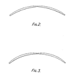
- the rear surface of the member 1B may be continuously varying in inclination with respect to the rear face or vice versa as shown in Figures 2 and 3.
- Another possibility would be to form the grooves on the rear face.
- the diffuser 1A can be either to the rear or to the front of the member 1 B or could be dispensed with if the member 1 B were itself capable of diffusing the incident light. It could be surface treated for this purpose.
Landscapes
- Engineering & Computer Science (AREA)
- Theoretical Computer Science (AREA)
- Physics & Mathematics (AREA)
- General Physics & Mathematics (AREA)
- Computer Hardware Design (AREA)
- Educational Administration (AREA)
- Educational Technology (AREA)
- Business, Economics & Management (AREA)
- Aviation & Aerospace Engineering (AREA)
- Remote Sensing (AREA)
- Radar, Positioning & Navigation (AREA)
- Computer Graphics (AREA)
- Geometry (AREA)
- General Engineering & Computer Science (AREA)
- Processing Or Creating Images (AREA)
- Image Generation (AREA)
- Overhead Projectors And Projection Screens (AREA)
- Devices For Indicating Variable Information By Combining Individual Elements (AREA)
- Optical Elements Other Than Lenses (AREA)
Description
- This invention arose in the design of a simulator for training crew for aircraft, ships and land vehicles and relates particularly to computer generated imagery techniques for such a simulator.
- Particularly where it is desired to simulate a scene for training a ship's crew or captain, or where it is desired for more than one person to view the same screen, it is necessary to provide a particularly large screen, which preferably curves around the observer so as to provide a wide angle of view. In such circumstances it may be necessary to illuminate the screen using two or more projectors at different positions. Initial attempts to build a suitable multiple-projector display like this suffered from the problem that a dividing line could be seen where the part of the image displayed by one projector joined another part displayed by another projector. This dividing line arose because the observer, when located at certain positions in front of the screen was more directly in line with one projector than the other. Thus, to reach the observer, tight from one projector had to be diffused through a larger angle than that from the other projector. Hence one part of the picture appeared less bright than the other: thus resulting in the dividing line between the parts of the picture.
- This problem is mitigated by the present invention which provides a display system comprising a screen and two spaced projectors arranged to illuminate respective parts of the screen, the screen comprising: diffusion means serving to scatter light incident on it at a particular point in a manner such that more of said light is propagated, after scattering, in a given direction of maximum intensity than in other directions; and refraction means serving to deflect the light before or after scattering from adjacent points of the said different parts so as to reduce or eliminate an angle between the directions of maximum intensity for said adjacent points.
- Back projection screens having diffusion means and refraction means are in themselves well known, e.g. as described in U.S.A. 3784742 and 3809457. They have not hitherto, however, addressed themselves to the aforementioned problem.
- One way in which the invention may be performed will now be described with reference to the accompanying drawings in which:-
- Figure 1 illustrates a display screen constructed in accordance with the invention and
- Figures 2 and 3 illustrate alternative screens to that shown in Figure 1.
- Figure 1 shows the screen 1 onto which a picture to be displayed is projected by the
projectors layer 1A of translucent material on its side closest to the projectors. Thislayer 1A serves as a diffuser of light. Theobserver 2 is located at the centre of curvature of the part cylindrical screen which has a radius D chosen to be sufficiently large to ensure that the projected image on the screen gives a sufficiently approximate illusion of being at infinity. This is because most of the images to be displayed are intended to be of distant objects and features. It is important td note that no diffuser is perfect and that more light incident on it in a given direction continues travelling close to that direction after diffusion than is diffused in any particular direction to the left or to the right. Thus, if one ignores the effect of themember 1 B, to be described later, theobserver 2 will receive a higher proportion of the light diffused frompoints points points points 1C and 1D is diffused not at all. Thus, in the illustrated system, the picture would, but for the presence of themember 1E, appear to anobserver 2 to be brighter at positions near 1C and 10 thannear positions positions 2A or 2B, i.e., to the left or to the right. When the observer is at theposition 2A thepoint 1E is directly in line with theprojector 30B and so thepoint 1E appears relatively bright. However, light received by the observer at 2A frompoint 1F has been diffused through a large angle sopoint 1 F appears relatively dim. The observer thus sees a vertical line down the centre of the screen dividing relatively bright areas illuminated byprojector 30B from relatively dim areas illuminated byprojector 30A. The aforementioned explanation assumes that the desired brightness of the simulated picture is constant over the whole screen. In practice this is, of course, not often the case but the effects described above often appear to a greater or lesser degree. - The problem described in the immediately preceding paragraph is mitigated by the use of the part cylindrical
transparent sheet 1B. This is located immediately in front of thediffuser 1A. Thesheet 1B, which is of uniform thickness, is machined to form a series of vertical grooves. Each groove has aside 1 G which is approximately in alignment with theobserver 2 and aside 1H which is inclined with respect to therear surface 11 of the acrylic sheet. The angle of inclination varies from groove to groove and is smallestnear points 1C and 1D in line with the projectors and theobserver 2. The angle progressively increases with increasing distance from thesepoints 1C and 1 D. The direction of inclination of any one face is away from the straight line between theobserver 2 and the projector illuminating that face. Thus, eachinclined face 1H defines, with therear surface 11, a prism which deflects light derived from one of the projectors towards the straight line between the projector and theobserver 2. Each part of thesheet 1B, illuminated by a givenprojector screen 1A) light from that projector onto theobserver position 2. - Considering now the
points lines 1J and 1K which are almost parallel. Thus, the observer at 2A is offset from these directions by approximately equal angles; causing equal reductions in the brightness of thepoints 1E and 1 F. The sharp dividing line previously mentioned is thus eliminated. Similar comments apply to the observer when he moves to or towards the position 2B. - The grooves machined in the
sheet 1 B may vary in depth and/or width. As an alternative to forming such grooves the rear surface of themember 1B may be continuously varying in inclination with respect to the rear face or vice versa as shown in Figures 2 and 3. Another possibility would be to form the grooves on the rear face. Thediffuser 1A can be either to the rear or to the front of themember 1 B or could be dispensed with if themember 1 B were itself capable of diffusing the incident light. It could be surface treated for this purpose. - In some circumstances it may be desired to have a screen which extends through a larger arc than that illustrated. In this case further projectors could be used and the screen would be formed of more than the two sections illustrated.
Claims (5)
Priority Applications (2)
| Application Number | Priority Date | Filing Date | Title |
|---|---|---|---|
| DE8282302630T DE3262958D1 (en) | 1981-05-22 | 1982-05-21 | Display system |
| AT82302630T ATE12703T1 (en) | 1981-05-22 | 1982-05-21 | PROJECTION DEVICE. |
Applications Claiming Priority (2)
| Application Number | Priority Date | Filing Date | Title |
|---|---|---|---|
| GB8115866 | 1981-05-22 | ||
| GB8115866 | 1981-05-22 |
Related Parent Applications (1)
| Application Number | Title | Priority Date | Filing Date |
|---|---|---|---|
| EP82302630.7 Division | 1982-05-21 |
Related Child Applications (5)
| Application Number | Title | Priority Date | Filing Date |
|---|---|---|---|
| EP82302630.7 Division-Into | 1982-05-21 | ||
| EP84106682.2 Division-Into | 1984-06-12 | ||
| EP84106681.4 Division-Into | 1984-06-12 | ||
| EP84106679.8 Division-Into | 1984-06-12 | ||
| EP84106680.6 Division-Into | 1984-06-12 |
Publications (2)
| Publication Number | Publication Date |
|---|---|
| EP0066998A1 EP0066998A1 (en) | 1982-12-15 |
| EP0066998B1 true EP0066998B1 (en) | 1985-04-10 |
Family
ID=10522020
Family Applications (5)
| Application Number | Title | Priority Date | Filing Date |
|---|---|---|---|
| EP82302630A Expired EP0066998B1 (en) | 1981-05-22 | 1982-05-21 | Display system |
| EP84106680A Ceased EP0137108A1 (en) | 1981-05-22 | 1982-05-21 | A raster display system |
| EP84106682A Ceased EP0137110A1 (en) | 1981-05-22 | 1982-05-21 | Apparatus for generating successive picture frames depicting a feature to create an illusion of movement |
| EP84106681A Ceased EP0137109A1 (en) | 1981-05-22 | 1982-05-21 | Image generating apparatus for producing from the co-ordinates of the end points of a line, a two-dimensional image depicting the line as viewed by the observer |
| EP84106679A Ceased EP0137107A1 (en) | 1981-05-22 | 1982-05-21 | A computer generated imagery system |
Family Applications After (4)
| Application Number | Title | Priority Date | Filing Date |
|---|---|---|---|
| EP84106680A Ceased EP0137108A1 (en) | 1981-05-22 | 1982-05-21 | A raster display system |
| EP84106682A Ceased EP0137110A1 (en) | 1981-05-22 | 1982-05-21 | Apparatus for generating successive picture frames depicting a feature to create an illusion of movement |
| EP84106681A Ceased EP0137109A1 (en) | 1981-05-22 | 1982-05-21 | Image generating apparatus for producing from the co-ordinates of the end points of a line, a two-dimensional image depicting the line as viewed by the observer |
| EP84106679A Ceased EP0137107A1 (en) | 1981-05-22 | 1982-05-21 | A computer generated imagery system |
Country Status (3)
| Country | Link |
|---|---|
| US (1) | US4616217A (en) |
| EP (5) | EP0066998B1 (en) |
| GB (6) | GB2100099B (en) |
Families Citing this family (52)
| Publication number | Priority date | Publication date | Assignee | Title |
|---|---|---|---|---|
| JPS58154146A (en) * | 1982-03-10 | 1983-09-13 | Sony Corp | Liquid cooling type cathode-ray tube |
| GB2123656B (en) * | 1982-06-09 | 1987-02-18 | Tatsumi Denshi Kogyo Kk | A method and an apparatus for displaying a unified picture on crt screens of multiple displaying devices |
| DE3474607D1 (en) * | 1983-03-09 | 1988-11-17 | Nippon Denso Co | Map display system |
| GB2138252B (en) * | 1983-04-12 | 1986-10-22 | Marconi Co Ltd | Image generator |
| US4473355A (en) * | 1983-06-30 | 1984-09-25 | Messerschmitt-Boelkow-Blohm Gesellschaft Mit Beschraenkter Haftung | Visual simulator and display screen for said simulator |
| US4682160A (en) * | 1983-07-25 | 1987-07-21 | Harris Corporation | Real time perspective display employing digital map generator |
| US4615013A (en) * | 1983-08-02 | 1986-09-30 | The Singer Company | Method and apparatus for texture generation |
| DE3475565D1 (en) * | 1984-02-17 | 1989-01-12 | Honeywell Regelsysteme Gmbh | View simulating device |
| US4882763A (en) * | 1984-12-31 | 1989-11-21 | The Standard Oil Company | Method of making a rock-pore micromodel involving generation of an accurate and reliable template image of an actual reservoir rock pore system |
| CA1250644A (en) * | 1984-12-31 | 1989-02-28 | Robert Ehrlich | Method of making rock-pore micromodel involving generation of an accurate and reliable template image of an actual reservoir rock pore system |
| US4763280A (en) * | 1985-04-29 | 1988-08-09 | Evans & Sutherland Computer Corp. | Curvilinear dynamic image generation system |
| US4710767A (en) * | 1985-07-19 | 1987-12-01 | Sanders Associates, Inc. | Method and apparatus for displaying multiple images in overlapping windows |
| DE3532568A1 (en) * | 1985-09-12 | 1987-03-19 | Dornier System Gmbh | METHOD FOR DIGITIZING AND PRESENTING COLORED MAPS |
| GB2181929B (en) * | 1985-10-21 | 1989-09-20 | Sony Corp | Methods of and apparatus for video signal processing |
| FR2674652A1 (en) * | 1986-03-04 | 1992-10-02 | Thomson Csf | Process and device for synthesising three-dimensional moving map images |
| GB8605713D0 (en) * | 1986-03-07 | 1986-10-29 | Gec Avionics | Displays |
| US4805121A (en) * | 1986-05-30 | 1989-02-14 | Dba Systems, Inc. | Visual training apparatus |
| JPH0640340B2 (en) * | 1986-07-31 | 1994-05-25 | 株式会社日立製作所 | Data display |
| JPH01501178A (en) * | 1986-09-11 | 1989-04-20 | ヒューズ・エアクラフト・カンパニー | Digital visual sensing simulation system for photorealistic screen formation |
| US4870397A (en) * | 1986-11-05 | 1989-09-26 | Grumman Aerospace Corporation | System for producing graphic displays and programs for generating same |
| US4853769A (en) * | 1987-06-16 | 1989-08-01 | Massachusetts Institute Of Technology | Time multiplexed auto-stereoscopic three-dimensional imaging system |
| US5189732A (en) * | 1987-11-18 | 1993-02-23 | Hitachi, Ltd. | Touch panel input apparatus |
| JP3138264B2 (en) * | 1988-06-21 | 2001-02-26 | ソニー株式会社 | Image processing method and apparatus |
| JPH05505033A (en) * | 1990-02-16 | 1993-07-29 | ナディメリア (オーバーシーズ) リミテッド | display system |
| JPH079504B2 (en) * | 1990-04-25 | 1995-02-01 | 松下電器産業株式会社 | Bidirectional recognition head-up display device |
| US5547382A (en) * | 1990-06-28 | 1996-08-20 | Honda Giken Kogyo Kabushiki Kaisha | Riding simulation system for motorcycles |
| JPH04182696A (en) * | 1990-11-17 | 1992-06-30 | Nintendo Co Ltd | Image processor |
| US5371512A (en) * | 1990-11-19 | 1994-12-06 | Nintendo Co., Ltd. | Background picture display apparatus and external storage used therefor |
| US6643656B2 (en) * | 1991-07-31 | 2003-11-04 | Richard Esty Peterson | Computerized information retrieval system |
| GB2261144B (en) * | 1991-10-30 | 1995-06-21 | Thomson Consumer Electronics | Apparatus for generating graphics |
| US5377314A (en) * | 1992-12-21 | 1994-12-27 | International Business Machines Corporation | Method and system for selective display of overlapping graphic objects in a data processing system |
| US5604857A (en) * | 1993-01-15 | 1997-02-18 | Walmsley; Simon R. | Render system for the rendering of storyboard structures on a real time animated system |
| JP3052681B2 (en) * | 1993-08-06 | 2000-06-19 | 松下電器産業株式会社 | 3D video generation device |
| US5551011A (en) * | 1994-01-27 | 1996-08-27 | Huyck Licensco, Inc. | Computerized system for simulating paper sheet formation and the appearance of print thereon |
| CA2144914A1 (en) * | 1994-04-01 | 1995-10-02 | Raymond L. Fitzgerald | Computer graphics texture paging system with fragmentary mip map selection |
| US5621431A (en) * | 1994-04-29 | 1997-04-15 | Atari Games Corporation | Animation system having variable video display rate |
| US6011566A (en) * | 1994-09-01 | 2000-01-04 | Unisys Corporation | System and method to display raster images with negligible delay time and reduced memory requirements |
| US5541769A (en) * | 1994-11-18 | 1996-07-30 | Hughes Training, Inc. | Uniform-brightness, high-gain display structures and methods |
| US5561749A (en) * | 1994-12-02 | 1996-10-01 | General Electric Company | Modeling of surfaces employing polygon strips |
| FR2740888B1 (en) * | 1995-11-03 | 1997-11-28 | Thomson Csf | METHOD OF DYNAMICALLY GENERATING SYNTHETIC IMAGES AT AUTOMATIC DETAIL LEVEL, AND DEVICE FOR IMPLEMENTING SAME |
| US5818453A (en) * | 1996-01-05 | 1998-10-06 | Weavexx Corporation | System for evaluating print quality for a sheet |
| KR100255758B1 (en) * | 1997-11-21 | 2000-05-01 | 전주범 | Method for searching a triangle corresponding to a location of an object moving on trigonometric grids |
| US6059268A (en) * | 1998-05-06 | 2000-05-09 | Santelli, Jr.; Albert | Bumper system for limiting the mobility of a wheeled device |
| US7491063B1 (en) | 2004-05-14 | 2009-02-17 | Paul Santarsiero | Harmony meter |
| US20060164417A1 (en) * | 2004-07-28 | 2006-07-27 | Lockheed Martin Corporation | Imagery-based synthetic environment for computer generated forces |
| CN101617354A (en) | 2006-12-12 | 2009-12-30 | 埃文斯和萨瑟兰计算机公司 | Be used for calibrating the system and method for the rgb light of single modulator projector |
| US8358317B2 (en) | 2008-05-23 | 2013-01-22 | Evans & Sutherland Computer Corporation | System and method for displaying a planar image on a curved surface |
| US8702248B1 (en) | 2008-06-11 | 2014-04-22 | Evans & Sutherland Computer Corporation | Projection method for reducing interpixel gaps on a viewing surface |
| US8077378B1 (en) | 2008-11-12 | 2011-12-13 | Evans & Sutherland Computer Corporation | Calibration system and method for light modulation device |
| CN102052898B (en) * | 2009-11-02 | 2013-07-24 | 重庆工商大学 | Method for measuring small two-dimensional displacement by using three primary colors of computer camera |
| US9641826B1 (en) | 2011-10-06 | 2017-05-02 | Evans & Sutherland Computer Corporation | System and method for displaying distant 3-D stereo on a dome surface |
| CN104821117A (en) * | 2015-05-28 | 2015-08-05 | 江南大学 | Triangle segment segmentation illusion viewer |
Family Cites Families (27)
| Publication number | Priority date | Publication date | Assignee | Title |
|---|---|---|---|---|
| GB596813A (en) * | 1945-06-08 | 1948-01-12 | Cinema Television Ltd | Improvements in or relating to screens for viewing projected optical images |
| GB606010A (en) * | 1945-03-17 | 1948-08-04 | Marconi Wireless Telegraph Co | Improvements in optical projection screens |
| US3621214A (en) * | 1968-11-13 | 1971-11-16 | Gordon W Romney | Electronically generated perspective images |
| US3684876A (en) * | 1970-03-26 | 1972-08-15 | Evans & Sutherland Computer Co | Vector computing system as for use in a matrix computer |
| US3644935A (en) * | 1970-05-14 | 1972-02-22 | Ibm | Method of identifying connected regions in a large segmented pattern |
| GB1385908A (en) * | 1971-05-12 | 1975-03-05 | Redifon Ltd | Visual display apparatus |
| US3810138A (en) * | 1972-01-10 | 1974-05-07 | Westinghouse Electric Corp | Interpolative sensor output visual map display system |
| US3763365A (en) * | 1972-01-21 | 1973-10-02 | Evans & Sutherland Computer Co | Computer graphics matrix multiplier |
| US3809457A (en) * | 1972-10-13 | 1974-05-07 | Eastman Kodak Co | Radiation-redistributive devices |
| US3889107A (en) * | 1972-10-16 | 1975-06-10 | Evans & Sutherland Computer Co | System of polygon sorting by dissection |
| US3816726A (en) * | 1972-10-16 | 1974-06-11 | Evans & Sutherland Computer Co | Computer graphics clipping system for polygons |
| JPS49114434A (en) * | 1973-02-12 | 1974-10-31 | ||
| US3909525A (en) * | 1973-12-10 | 1975-09-30 | Rockwell International Corp | Display system optics |
| JPS5189419A (en) * | 1975-02-03 | 1976-08-05 | ||
| JPS583530B2 (en) * | 1975-02-28 | 1983-01-21 | ソニー株式会社 | rear projector armchair |
| IL51719A (en) * | 1976-04-08 | 1979-11-30 | Hughes Aircraft Co | Raster type display system |
| US4152766A (en) * | 1978-02-08 | 1979-05-01 | The Singer Company | Variable resolution for real-time simulation of a polygon face object system |
| US4181953A (en) * | 1978-02-17 | 1980-01-01 | The Singer Company | Face vertex correction for real-time simulation of a polygon face object system |
| GB2019336B (en) * | 1978-04-22 | 1982-06-16 | Redifon Simulation Ltd | Visual display apparatus for flight simulators |
| GB2021905B (en) * | 1978-05-12 | 1982-03-31 | Smiths Industries Ltd | Display systems and control systems therefor |
| US4208719A (en) * | 1978-08-10 | 1980-06-17 | The Singer Company | Edge smoothing for real-time simulation of a polygon face object system as viewed by a moving observer |
| JPS5941222B2 (en) * | 1978-08-30 | 1984-10-05 | 株式会社日立製作所 | graphic display device |
| US4208810A (en) * | 1978-09-11 | 1980-06-24 | The Singer Company | Clipping polygon faces through a polyhedron of vision |
| GB2043972B (en) * | 1979-01-26 | 1983-09-01 | Thomas A L | Display processors |
| US4241341A (en) * | 1979-03-05 | 1980-12-23 | Thorson Mark R | Apparatus for scan conversion |
| US4291380A (en) * | 1979-05-14 | 1981-09-22 | The Singer Company | Resolvability test and projection size clipping for polygon face display |
| GB2051525A (en) * | 1979-06-15 | 1981-01-14 | Redifon Simulation Ltd | C.G.I.-Surface textures |
-
1982
- 1982-05-20 US US06/380,295 patent/US4616217A/en not_active Expired - Fee Related
- 1982-05-21 GB GB8214844A patent/GB2100099B/en not_active Expired
- 1982-05-21 EP EP82302630A patent/EP0066998B1/en not_active Expired
- 1982-05-21 GB GB8214843A patent/GB2100098B/en not_active Expired
- 1982-05-21 GB GB8214842A patent/GB2100556B/en not_active Expired
- 1982-05-21 EP EP84106680A patent/EP0137108A1/en not_active Ceased
- 1982-05-21 EP EP84106682A patent/EP0137110A1/en not_active Ceased
- 1982-05-21 EP EP84106681A patent/EP0137109A1/en not_active Ceased
- 1982-05-21 GB GB8214845A patent/GB2100100B/en not_active Expired
- 1982-05-21 EP EP84106679A patent/EP0137107A1/en not_active Ceased
- 1982-05-21 GB GB08214841A patent/GB2104759B/en not_active Expired
- 1982-05-21 GB GB08214840A patent/GB2101767B/en not_active Expired
Also Published As
| Publication number | Publication date |
|---|---|
| EP0137108A1 (en) | 1985-04-17 |
| GB2104759A (en) | 1983-03-09 |
| EP0066998A1 (en) | 1982-12-15 |
| GB2101767B (en) | 1985-01-16 |
| GB2104759B (en) | 1985-01-16 |
| GB2100556B (en) | 1985-08-21 |
| EP0137110A1 (en) | 1985-04-17 |
| GB2100100B (en) | 1985-08-21 |
| EP0137109A1 (en) | 1985-04-17 |
| GB2100098A (en) | 1982-12-15 |
| EP0137107A1 (en) | 1985-04-17 |
| GB2100556A (en) | 1982-12-22 |
| GB2100099A (en) | 1982-12-15 |
| GB2101767A (en) | 1983-01-19 |
| GB2100098B (en) | 1985-06-19 |
| GB2100099B (en) | 1984-12-05 |
| US4616217A (en) | 1986-10-07 |
| GB2100100A (en) | 1982-12-15 |
Similar Documents
| Publication | Publication Date | Title |
|---|---|---|
| GB2101767A (en) | A display system comprising a screen and two speed projectors for illuminating respective parts thereof | |
| US5329323A (en) | Apparatus and method for producing 3-dimensional images | |
| US4220400A (en) | Display apparatus with reflective separated structure | |
| US5189452A (en) | Real image projection system | |
| US3582961A (en) | System for displaying a two-dimensional photographic picture in three dimensions | |
| KR910700594A (en) | 3D display device | |
| Gibson et al. | A method of controlling stimulation for the study of space perception: the optical tunnel. | |
| AU6540590A (en) | Method and apparatus for illumination of a liquid droplet fountain to produce rainbows | |
| US5291297A (en) | Illustion creating apparatus comprising a housing and a CRT | |
| US3502402A (en) | Multiple image projection system | |
| EP0926573A3 (en) | One-visual-point image display apparatus and multi-visual-points image display apparatus | |
| GB1414284A (en) | Optical image superimposing apparatus | |
| US3820873A (en) | Screen for producing an enhanced impression of depth | |
| AU777830B2 (en) | Projection system | |
| WO2000003271A2 (en) | Projection system | |
| US2660927A (en) | Projection screen | |
| WO1984001654A1 (en) | Optical displays | |
| JP3004568U (en) | Lightning display 3D sign | |
| US4455067A (en) | Method of modifying slide transparencies so as to provide uniform illumination in angular projection | |
| GB2022861A (en) | Rear Projection Screen | |
| US3776621A (en) | Optical display system and method for creating a theatrical illusion | |
| US5589979A (en) | Simulator arrangement | |
| US3180211A (en) | Means for providing an optical third dimension in motion pictures | |
| WO2004099842A1 (en) | Image display apparatus | |
| EP0814453A2 (en) | Illumination apparatus |
Legal Events
| Date | Code | Title | Description |
|---|---|---|---|
| PUAI | Public reference made under article 153(3) epc to a published international application that has entered the european phase |
Free format text: ORIGINAL CODE: 0009012 |
|
| AK | Designated contracting states |
Designated state(s): AT BE CH DE FR IT LI NL SE |
|
| 17P | Request for examination filed |
Effective date: 19830304 |
|
| ITF | It: translation for a ep patent filed | ||
| GRAA | (expected) grant |
Free format text: ORIGINAL CODE: 0009210 |
|
| AC | Divisional application: reference to earlier application |
Ref document number: 66998 Country of ref document: EP |
|
| AK | Designated contracting states |
Designated state(s): AT BE CH DE FR IT LI NL SE |
|
| PG25 | Lapsed in a contracting state [announced via postgrant information from national office to epo] |
Ref country code: AT Effective date: 19850410 |
|
| REF | Corresponds to: |
Ref document number: 12703 Country of ref document: AT Date of ref document: 19850415 Kind code of ref document: T |
|
| REF | Corresponds to: |
Ref document number: 3262958 Country of ref document: DE Date of ref document: 19850515 |
|
| PGFP | Annual fee paid to national office [announced via postgrant information from national office to epo] |
Ref country code: NL Payment date: 19850531 Year of fee payment: 4 |
|
| ET | Fr: translation filed | ||
| PLBE | No opposition filed within time limit |
Free format text: ORIGINAL CODE: 0009261 |
|
| STAA | Information on the status of an ep patent application or granted ep patent |
Free format text: STATUS: NO OPPOSITION FILED WITHIN TIME LIMIT |
|
| 26N | No opposition filed | ||
| PG25 | Lapsed in a contracting state [announced via postgrant information from national office to epo] |
Ref country code: SE Effective date: 19860522 |
|
| PG25 | Lapsed in a contracting state [announced via postgrant information from national office to epo] |
Ref country code: LI Effective date: 19860531 Ref country code: CH Effective date: 19860531 |
|
| PG25 | Lapsed in a contracting state [announced via postgrant information from national office to epo] |
Ref country code: NL Effective date: 19861201 |
|
| NLV4 | Nl: lapsed or anulled due to non-payment of the annual fee | ||
| REG | Reference to a national code |
Ref country code: CH Ref legal event code: PL |
|
| BERE | Be: lapsed |
Owner name: THE MARCONI CY LTD Effective date: 19870531 |
|
| PG25 | Lapsed in a contracting state [announced via postgrant information from national office to epo] |
Ref country code: FR Free format text: LAPSE BECAUSE OF NON-PAYMENT OF DUE FEES Effective date: 19880129 |
|
| PG25 | Lapsed in a contracting state [announced via postgrant information from national office to epo] |
Ref country code: DE Effective date: 19880202 |
|
| REG | Reference to a national code |
Ref country code: FR Ref legal event code: ST |
|
| PG25 | Lapsed in a contracting state [announced via postgrant information from national office to epo] |
Ref country code: BE Effective date: 19890531 |
|
| EUG | Se: european patent has lapsed |
Ref document number: 82302630.7 Effective date: 19870225 |