EP0066600B1 - Energy absorbing structure - Google Patents
Energy absorbing structure Download PDFInfo
- Publication number
- EP0066600B1 EP0066600B1 EP82900114A EP82900114A EP0066600B1 EP 0066600 B1 EP0066600 B1 EP 0066600B1 EP 82900114 A EP82900114 A EP 82900114A EP 82900114 A EP82900114 A EP 82900114A EP 0066600 B1 EP0066600 B1 EP 0066600B1
- Authority
- EP
- European Patent Office
- Prior art keywords
- structure according
- sheet
- ridges
- wall
- tubular
- Prior art date
- Legal status (The legal status is an assumption and is not a legal conclusion. Google has not performed a legal analysis and makes no representation as to the accuracy of the status listed.)
- Expired
Links
Images


Classifications
-
- B—PERFORMING OPERATIONS; TRANSPORTING
- B62—LAND VEHICLES FOR TRAVELLING OTHERWISE THAN ON RAILS
- B62D—MOTOR VEHICLES; TRAILERS
- B62D21/00—Understructures, i.e. chassis frame on which a vehicle body may be mounted
- B62D21/15—Understructures, i.e. chassis frame on which a vehicle body may be mounted having impact absorbing means, e.g. a frame designed to permanently or temporarily change shape or dimension upon impact with another body
- B62D21/157—Understructures, i.e. chassis frame on which a vehicle body may be mounted having impact absorbing means, e.g. a frame designed to permanently or temporarily change shape or dimension upon impact with another body for side impacts
-
- B—PERFORMING OPERATIONS; TRANSPORTING
- B62—LAND VEHICLES FOR TRAVELLING OTHERWISE THAN ON RAILS
- B62D—MOTOR VEHICLES; TRAILERS
- B62D21/00—Understructures, i.e. chassis frame on which a vehicle body may be mounted
- B62D21/15—Understructures, i.e. chassis frame on which a vehicle body may be mounted having impact absorbing means, e.g. a frame designed to permanently or temporarily change shape or dimension upon impact with another body
- B62D21/152—Front or rear frames
-
- F—MECHANICAL ENGINEERING; LIGHTING; HEATING; WEAPONS; BLASTING
- F16—ENGINEERING ELEMENTS AND UNITS; GENERAL MEASURES FOR PRODUCING AND MAINTAINING EFFECTIVE FUNCTIONING OF MACHINES OR INSTALLATIONS; THERMAL INSULATION IN GENERAL
- F16F—SPRINGS; SHOCK-ABSORBERS; MEANS FOR DAMPING VIBRATION
- F16F7/00—Vibration-dampers; Shock-absorbers
- F16F7/12—Vibration-dampers; Shock-absorbers using plastic deformation of members
- F16F7/123—Deformation involving a bending action, e.g. strap moving through multiple rollers, folding of members
Definitions
- This invention relates to energy absorbing structures.
- Energy absorbing structures are used in assemblies which are susceptible to impact loads to control the amount of damage suffered by the assembly or to protect the occupants or contents thereof.
- energy absorbing structures are incorporated in motor vehicles to absorb impact energy and thereby reduce the risk of injury to passengers in containers for cargo to protect the cargo from damage by impact loads; and in air landing pallets to absorb ground impact loads when the pallet has been dropped from an aircraft, thereby protecting the load carried by the pallet.
- US-A-4227593 discloses an energy absorbing pad composed of a series of overlying sheets of corrugated metal secured together by tack welds and bolts to form a block having a honeycomb like cross-sectional shape.
- US-A-3466733, and DE-A-2334121 disclose energy absorbing cylinders formed from a coil of corrugated metal, adjacent windings of the coil being bonded to an interleaved sheet of plane of material.
- the buckling or folding usually proceeds in a relatively uncontrolled manner, particularly where the wall is not in the form of a tube.
- the wall may form an initial fold which then acts as a hinge around which the whole structure can then bend. After such large scale bending of the stucture has started to occur the structure offers little resistance to the applied load and the amount of additional energy absorbed by the structure is relatively small.
- an energy absorbing structure which has a laminar or hollow tubular shape and which is formed from a sheet of deformable material having a plurality of parallel ridges extending in a longitudinal direction, and at least one reinforcement secured to the sheet on or adjacent to each ridge at one or more discrete points spaced along the length of the wall, characterised in that the dimensions of the ridges and the spacing between the said points and the ends of the sheet are such that the sheet collapses progressively with substantially no large scale bending when a load is applied thereto in the longitudinal direction.
- the ridges may be formed by bending or moulding the sheet material of the wall, so that at least one ridge is formed by one or more folds of the longitudinally extending U-shaped ridge.
- the ridges may be generally U-shaped or V-shaped.
- a ridge may be formed by two mutually inclined surfaces each having a flange along one longitudinally extending edge, the flanges of the two surfaces being secured together in abutment with each other. It may be appropriate to use both these constructions in a single wall.
- the wall of the structure may be of any shape.
- it may be tubular or alternatively it may be planar or curved.
- the corrugations should extend along straight lines in the direction in which an impact load is expected to be applied.
- the wall has a square or rectangular cross-section.
- the reinforcements may generally take the form of straps. Where the wall is tubular, the reinforcements may be in the form of a plate extending diametrically across the tube or, preferably, a tube coaxial with the wall and secured thereto along its length. The tube may lie outside, or preferably, within the tubular wall.
- any deformable material may be used for the wall.
- a flexible plastics material may be used.
- a metal would be more suitable. Aluminium is a preferred metal in view of its light weight. Mild steel can however also be used.
- the body panel may be in the form of a vehicle suspension mounting panel which in use is aligned in the fore-and-aft direction.
- the ridges also extend in the fore-and-aft direction so that the structure absorbs frontal impact loads.
- the body panel may comprise a motor vehicle floor pan, especially a rear seat support and the ridges extend in the transverse direction of the vehicle so that the structure absorbs side impact loads.
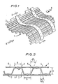
- an energy absorbing structure 1 comprises a wall 2 composed of a sheet metal such as aluminium.
- the sheet is formed with a plurality of ridges or corrugations 3 which extend parallel to each other in a longitudinal direction.
- the ridges may be formed by carrying out a series of bending operations on a flat blank of metal, or by pressing the flat blank between two dies.
- the ridges are generally U-shaped with inclined side walls so that each ridge has two parallel fold lines 4, 5 extending longitudinally along its length.
- the wall 2 carries a set of spaced reinforcements in the form of straps 6 which are also made of aluminium.
- the straps extend transversely to the ridges and are fixed by means of rivets 7, at points adjacent to and on top of each ridge, the straps 6 being disposed in pairs opposite each other on either side of the wall.
- the straps may be secured to the wall by welding or by a suitable adhesive such as an epoxide resin.
- the structure may be shaped to any desired curvature in the transverse direction, provided that the ridges remain aligned along parallel straight lines.
- FIG. 3 illustrates the behaviour of such a structure under such a load. It can be seen that each ridge 3 folds into a large number of convolutions 8 whilst the structure 1 itself retains its generally longitudinal alignment without bending. Continued application of the load causes the folding to continue progressively along the structure past each of the straps 6 in turn. Since the formation of each successive fold in the wall requires additional energy, the total amount of energy absorbed by the structure is extremely high.
- FIG 4 a structure 10 similar to that shown in Figure 2 is illustrated after having been loaded in a manner similar to that described with reference to Figure 3.
- the structure 10 has ridges 3 similar to the structure 2 of Figure 2, it has no reinforcing straps 6. It can be seen that the application of a compressive load in the direction of the arrow A causes bending of the structure generally about a central pivot region 11. Once such bending has started the structure offers a much smaller resistance to the load and rapidly collapses in an uncontrolled manner. The total energy absorbed by the structure is therefore substantially less than that absorbed by the structure of the invention.
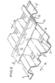
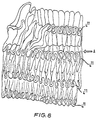
- FIGs 5 and 6 illustrate an alternative structure in accordance with the invention in which the ridges 3' are shaped similarly to that illustrated in Figures 1 and 2.
- the straps 6', 6' however are provided with tabs 12, 12 which project from the spine 13 of the straps 6' outwardly and downwardly into the channels between adjacent ridges 3'.
- the straps may then be secured to the wall at points adjacent to and on top of ridge 3' by riveting or welding at the ends of the tabs 12, as indicated at 14, and at the spine 13, as indicated at 15 in Figure 6.
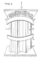
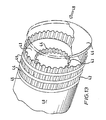
- Figures 7 and 8 illustrate a further alternative embodiment of the invention, before and after collapse under load.
- the wall 2" is tubular with V-shaped ridges 3" arranged axially.
- the reinforcements comprise hexagonal plates 15, 15 arranged diametrically across the interior of the tubular wall.
- the plates each have upstanding flanges 16 which are riveted to the wall 2" between the ridges 3" as indicated at 17.
- the tube is 15 cm in diameter
- the reinforcements 15, 15 and the wall 2" are composed of 20 gauge aluminium plate
- the ridges are formed with two 25 mm side walls inclined at 60° and the spacings between the two reinforcements and the ends of the tube are no greater than 15 cm.
- Figure 8 illustrates the tube after collapse.
- a compressive axial load in the direction of the arrow A of more than 58 kN is required to effect this collapse.
- the collapse occurs progressively in a controlled manner by the sequential formation of folds along the ridges 4" of the ridges 3".
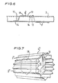
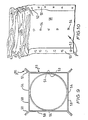
- Figures 9 and 10 illustrate a third embodiment of the invention in which the wall 2"' is tubular with a square cross-sectional shape.
- the four sides of the tubular wall are formed from four separate plates 50 each of which is provided with a 45° flange 51 along its two longitudinally extending edges.
- the flanges of the adjacent plates 50 are secured together in abutment with each other by spot welding, as indicated at 52 in Figure 10, so that the surfaces of adjacent pairs of plates 50 form the four V-shaped ridges 3"' along the length of the wall.
- the reinforcement comprises a single cylindrical tube 53 positioned within the wall 2"' in contact with each of the four plates 50 and secured thereto adjacent each ridge 3'" by a series of spot welds 54 ( Figure 10) extending along the length of the wall 2"'.
- the wall 2" has an internal cross-sectional length of 8 cm
- the wall 2"' and the reinforcement 53 are composed of 22 gauge mild steel and the spot welds 54 are spaced apart by no more than 3 cm in the longitudinal direction.
- the structure has good collapse characteristics under loads applied in the direction of the ridges 3"'.
- FIGs 11 and 12 illustrate motor vehicle body panels incorporating energy absorbing structures in accordance with the invention.
- the panel 19 is a mounting for a road wheel suspension arm 20 illustrated on the fore-and-aft direction of the vehicle and the forward part of the panel includes a wall 25 having ridges 26 which are aligned parallel with the fore-and-aft direction. Straps 27 are secured to both faces of the wall 25 in the manner described with reference to Figures 1 and 2. By suitably shaping the corrugations and spacing the straps 27, the panel 29 will collapse in a controlled manner on application of a frontal force indicated by the arrow 28.
- the panel 30 comprises a floor pan of a motor vehicle which is shaped to form the base of a rear seat in the vehicle adjacent a door aperture 31.
- the panel comprises ridges 32 which extend transversely of the vehicle and straps 33 secured to both faces of the panel and extending at right angles to the ridges. By suitably shaping the ridges and spacing straps 33, the panel will collapse in a controlled manner on application of a side load indicated by the arrow 34.
- Figure 13 illustrates a containerfor a road or rail vehicle incorporating an energy absorbing structure in accordance with the invention.
- the container comprises a cylindrical tank 40 having a domed end 41 carrying two tubular structures 42, 43 in accordance with the invention mounted concentrically.
- Each structure 42, 43 comprises a set of axially extending ridges 44 and circumferential straps 45.
- An end plate 46 is mounted on the ends of the energy absorbing structures 42, 43.
Landscapes
- Engineering & Computer Science (AREA)
- Mechanical Engineering (AREA)
- Chemical & Material Sciences (AREA)
- Combustion & Propulsion (AREA)
- Transportation (AREA)
- General Engineering & Computer Science (AREA)
- Body Structure For Vehicles (AREA)
- Vibration Dampers (AREA)
Applications Claiming Priority (6)
| Application Number | Priority Date | Filing Date | Title |
|---|---|---|---|
| GB8040041 | 1980-12-15 | ||
| GB8040041 | 1980-12-15 | ||
| GB8110795 | 1981-04-07 | ||
| GB8110795A GB2089464A (en) | 1980-12-15 | 1981-04-07 | Energy Absorbing Structure |
| GB8117069 | 1981-06-03 | ||
| GB8117069 | 1981-06-03 |
Publications (2)
| Publication Number | Publication Date |
|---|---|
| EP0066600A1 EP0066600A1 (en) | 1982-12-15 |
| EP0066600B1 true EP0066600B1 (en) | 1985-06-05 |
Family
ID=27261072
Family Applications (1)
| Application Number | Title | Priority Date | Filing Date |
|---|---|---|---|
| EP82900114A Expired EP0066600B1 (en) | 1980-12-15 | 1981-12-14 | Energy absorbing structure |
Country Status (6)
| Country | Link |
|---|---|
| US (1) | US4545172A (enExample) |
| EP (1) | EP0066600B1 (enExample) |
| JP (1) | JPS57502077A (enExample) |
| ES (1) | ES508002A0 (enExample) |
| IT (1) | IT1142106B (enExample) |
| WO (1) | WO1982002078A1 (enExample) |
Families Citing this family (22)
| Publication number | Priority date | Publication date | Assignee | Title |
|---|---|---|---|---|
| JPH07115586B2 (ja) * | 1986-10-27 | 1995-12-13 | 一仁 深澤 | 車体の衝撃吸収材 |
| JP2565377Y2 (ja) * | 1991-09-06 | 1998-03-18 | マツダ株式会社 | 自動車の前部車体構造 |
| US5251414A (en) * | 1992-03-16 | 1993-10-12 | Duke Darryl A | Energy absorbing composite and reinforcing core |
| US5314228A (en) * | 1993-03-16 | 1994-05-24 | Atlantic Research Corporation | Vehicle side impact intrusion barrier |
| US5884962A (en) * | 1996-09-12 | 1999-03-23 | Prince Corporation | Impact absorption member |
| US5879802A (en) * | 1996-09-12 | 1999-03-09 | Prince Corporation | Vehicle panel material |
| US6056349A (en) * | 1997-06-09 | 2000-05-02 | Aluminum Company Of America | Vehicle door having improved side crash resistance and associated method |
| US6012764A (en) * | 1997-06-11 | 2000-01-11 | Aluminum Company Of America | Vehicle greenhouse support assembly and associated method |
| DE19742603B4 (de) * | 1997-09-26 | 2005-08-18 | Volkswagen Ag | Doppellagenblech für ein Kraftfahrzeug |
| US6062632A (en) * | 1998-03-20 | 2000-05-16 | Solectria Corporation | Vehicle body collision energy absorption system |
| US6908143B2 (en) | 1998-11-21 | 2005-06-21 | Cellbond Limited | Energy-absorbing structure |
| US6547280B1 (en) * | 1998-11-21 | 2003-04-15 | Cellbond Limited | Energy-absorbing structures |
| US6779835B2 (en) | 2001-12-06 | 2004-08-24 | Lear Corporation | Energy absorbing structure for automobile interior |
| JP3964775B2 (ja) * | 2002-11-22 | 2007-08-22 | 本田技研工業株式会社 | 車両フロア構造 |
| US7338038B2 (en) | 2004-03-12 | 2008-03-04 | Dow Global Technologies, Inc. | Impact absorption structure |
| CN101227988B (zh) * | 2005-06-21 | 2012-01-25 | 布卢斯科普钢铁有限公司 | 屋顶包层板及屋顶包层组件 |
| DE102010052135A1 (de) * | 2010-11-22 | 2012-05-24 | Audi Ag | Crashstruktur für ein Kraftfahrzeug |
| US8770651B2 (en) | 2011-08-19 | 2014-07-08 | Leroy G. Hagenbuch | Off-highway truck body floor design |
| US9592853B2 (en) | 2014-07-02 | 2017-03-14 | GM Global Technology Operations LLC | Corrugation designs |
| US9650003B2 (en) * | 2014-07-02 | 2017-05-16 | GM Global Technology Operations LLC | Impact resistant component for a vehicle |
| CN107542824B (zh) * | 2017-10-13 | 2019-07-26 | 中国石油大学(华东) | 一种模仿环节动物的仿生减震结构 |
| FR3159588A1 (fr) | 2024-02-23 | 2025-08-29 | Airbus Operations (S.A.S) | Dispositif d’absorption d’énergie par compression comprenant des tubes d’absorption de forme étoilée, aéronef comportant au moins un tel dispositif |
Family Cites Families (25)
| Publication number | Priority date | Publication date | Assignee | Title |
|---|---|---|---|---|
| CA562919A (en) * | 1958-09-09 | W. Coffman Alden | Wall panel | |
| US346633A (en) * | 1886-08-03 | Surgical instrument | ||
| US164566A (en) * | 1875-06-15 | Improvement in fire-proof shutters | ||
| US1618476A (en) * | 1925-02-14 | 1927-02-22 | Rudolph A Riek | Refrigerator door |
| US2493562A (en) * | 1947-04-04 | 1950-01-03 | Ohio Boxboard Co | Loading pallet |
| FR974763A (fr) * | 1948-11-08 | 1951-02-26 | Dispositif de protection contre les chocs | |
| NL238234A (enExample) * | 1958-04-18 | |||
| US3466733A (en) * | 1963-05-31 | 1969-09-16 | American Cyanamid Co | Method of making shock absorber cartridge |
| US3564688A (en) * | 1966-07-14 | 1971-02-23 | Koppy Tool Corp | Method for forming a shock absorbing structural member |
| US3482367A (en) * | 1968-04-12 | 1969-12-09 | Robertson Co H H | Field erected insulated wall structure |
| US3506295A (en) * | 1968-10-14 | 1970-04-14 | Msl Ind Inc | Shock absorber bumper |
| GB1436175A (en) * | 1972-07-10 | 1976-05-19 | Nissan Motor | Vehicle having an oocupant knee protecting device |
| US3983963A (en) * | 1972-09-22 | 1976-10-05 | Nissan Motor Co., Ltd. | Multifacially formed panel impact absorber |
| JPS4950615A (enExample) * | 1972-09-22 | 1974-05-16 | ||
| FR2205147A5 (enExample) * | 1972-10-27 | 1974-05-24 | Chausson Usines Sa | |
| US3888531A (en) * | 1973-03-21 | 1975-06-10 | Straza Enterprises Ltd | Frangible shock absorbing bumper |
| US3831997A (en) * | 1973-03-22 | 1974-08-27 | Ford Motor Co | Controlled collapse vehicle front end structure |
| DE7324820U (de) * | 1973-07-05 | 1974-01-03 | Rasselstein Ag | Element zum Aufzehren kinetischer Energie durch plastische Verformung |
| FR2288648A1 (fr) * | 1974-03-05 | 1976-05-21 | Peugeot & Renault | Pare-chocs composite absorbeur d'energie |
| DE2441557A1 (de) * | 1974-08-30 | 1976-03-11 | Messerschmitt Boelkow Blohm | Anordnung zur abstuetzung eines stossfaengers |
| GB1489065A (en) * | 1975-05-22 | 1977-10-19 | British Steel Corp | Shock absorber |
| FR2315039A1 (fr) * | 1975-06-20 | 1977-01-14 | Berliet Automobiles | Dispositif a absorption d'energie, notamment pour les vehicules |
| DE2613655A1 (de) * | 1976-03-31 | 1977-10-13 | Volkswagenwerk Ag | Torsionssteifes, in laengs- und querrichtung bei geringen belastungen nachgiebiges rohrfoermiges bauteil |
| FR2362308A1 (fr) * | 1976-08-17 | 1978-03-17 | Commissariat Energie Atomique | Dispositif mecanique dissipateur d'energie |
| US4227593A (en) * | 1976-10-04 | 1980-10-14 | H. H. Robertson Company | Kinetic energy absorbing pad |
-
1981
- 1981-12-14 JP JP57500178A patent/JPS57502077A/ja active Pending
- 1981-12-14 US US06/414,259 patent/US4545172A/en not_active Expired - Lifetime
- 1981-12-14 WO PCT/GB1981/000270 patent/WO1982002078A1/en not_active Ceased
- 1981-12-14 EP EP82900114A patent/EP0066600B1/en not_active Expired
- 1981-12-15 IT IT25616/81A patent/IT1142106B/it active
- 1981-12-15 ES ES508002A patent/ES508002A0/es active Granted
Also Published As
| Publication number | Publication date |
|---|---|
| IT8125616A0 (it) | 1981-12-15 |
| JPS57502077A (enExample) | 1982-11-18 |
| ES8303636A1 (es) | 1983-02-01 |
| EP0066600A1 (en) | 1982-12-15 |
| US4545172A (en) | 1985-10-08 |
| IT1142106B (it) | 1986-10-08 |
| ES508002A0 (es) | 1983-02-01 |
| WO1982002078A1 (en) | 1982-06-24 |
Similar Documents
| Publication | Publication Date | Title |
|---|---|---|
| EP0066600B1 (en) | Energy absorbing structure | |
| EP0266084B1 (en) | Shock absorbing member for car body | |
| US6398275B1 (en) | Bumper arrangement | |
| US5868457A (en) | Structural member of vehicle body | |
| US5464266A (en) | Motor vehicle with a stiff floor structure | |
| US5560672A (en) | Energy absorbing beam | |
| US5931520A (en) | Light weight instrument panel reinforcement structure | |
| US6179353B1 (en) | High flex bumper with reinforced corner end sections | |
| US5653495A (en) | Reinforced door aperture frame for reducing deformation from offset collisions | |
| CN111051187B (zh) | 中空的部件 | |
| US11046156B2 (en) | Reinforced vehicle door against side impact | |
| JPH0665534B2 (ja) | エネルギ吸収装置 | |
| EP3414132B1 (en) | Impact energy absorbing structure | |
| EP4335729A1 (en) | Vehicle body | |
| US7275764B2 (en) | Vehicle occupant knee protection device | |
| CN114348119A (zh) | 用于电动车辆的并列型侧梁结构 | |
| WO2023090112A1 (ja) | 自動車の車体下部構造及びサイドシル構造 | |
| JPH0464247B2 (enExample) | ||
| CN121219170A (zh) | 滚轧成形的车辆加强梁 | |
| EP0580610B1 (en) | Vehicle and body | |
| CN120752172A (zh) | 具有锥形加强插入件的摇杆组件 | |
| SE515283C2 (sv) | Fordonsram för tunga fordon samt förfarande för tillverkning av en fordonsram | |
| GB2089464A (en) | Energy Absorbing Structure | |
| CN117529431A (zh) | 用于机动车辆的碰撞吸收元件 | |
| GB2087319A (en) | Support arrangement for the body of a motor vehicle especially a passenger car |
Legal Events
| Date | Code | Title | Description |
|---|---|---|---|
| PUAI | Public reference made under article 153(3) epc to a published international application that has entered the european phase |
Free format text: ORIGINAL CODE: 0009012 |
|
| 17P | Request for examination filed |
Effective date: 19820816 |
|
| AK | Designated contracting states |
Designated state(s): DE FR GB NL SE |
|
| GRAA | (expected) grant |
Free format text: ORIGINAL CODE: 0009210 |
|
| AK | Designated contracting states |
Designated state(s): DE FR GB NL SE |
|
| REF | Corresponds to: |
Ref document number: 3170905 Country of ref document: DE Date of ref document: 19850711 |
|
| ET | Fr: translation filed | ||
| PLBE | No opposition filed within time limit |
Free format text: ORIGINAL CODE: 0009261 |
|
| 26N | No opposition filed | ||
| REG | Reference to a national code |
Ref country code: GB Ref legal event code: 746 |
|
| REG | Reference to a national code |
Ref country code: FR Ref legal event code: DL |
|
| PGFP | Annual fee paid to national office [announced via postgrant information from national office to epo] |
Ref country code: NL Payment date: 19911231 Year of fee payment: 11 |
|
| PGFP | Annual fee paid to national office [announced via postgrant information from national office to epo] |
Ref country code: SE Payment date: 19921214 Year of fee payment: 12 |
|
| PG25 | Lapsed in a contracting state [announced via postgrant information from national office to epo] |
Ref country code: NL Effective date: 19930701 |
|
| NLV4 | Nl: lapsed or anulled due to non-payment of the annual fee | ||
| PG25 | Lapsed in a contracting state [announced via postgrant information from national office to epo] |
Ref country code: SE Effective date: 19931215 |
|
| EUG | Se: european patent has lapsed |
Ref document number: 82900114.8 Effective date: 19940710 |
|
| PGFP | Annual fee paid to national office [announced via postgrant information from national office to epo] |
Ref country code: GB Payment date: 19981130 Year of fee payment: 18 |
|
| PGFP | Annual fee paid to national office [announced via postgrant information from national office to epo] |
Ref country code: FR Payment date: 19981221 Year of fee payment: 18 |
|
| PGFP | Annual fee paid to national office [announced via postgrant information from national office to epo] |
Ref country code: DE Payment date: 19991123 Year of fee payment: 19 |
|
| PG25 | Lapsed in a contracting state [announced via postgrant information from national office to epo] |
Ref country code: GB Free format text: LAPSE BECAUSE OF NON-PAYMENT OF DUE FEES Effective date: 19991214 |
|
| REG | Reference to a national code |
Ref country code: FR Ref legal event code: TP |
|
| GBPC | Gb: european patent ceased through non-payment of renewal fee |
Effective date: 19991214 |
|
| PG25 | Lapsed in a contracting state [announced via postgrant information from national office to epo] |
Ref country code: FR Free format text: LAPSE BECAUSE OF NON-PAYMENT OF DUE FEES Effective date: 20000831 |
|
| REG | Reference to a national code |
Ref country code: FR Ref legal event code: ST |
|
| PG25 | Lapsed in a contracting state [announced via postgrant information from national office to epo] |
Ref country code: DE Free format text: LAPSE BECAUSE OF NON-PAYMENT OF DUE FEES Effective date: 20011002 |