EP0066191B1 - Dispositif de commande d'un convertisseur statique alternatif-alternatif à thyristors alimentant à fréquence variable une machine tournante synchrone - Google Patents
Dispositif de commande d'un convertisseur statique alternatif-alternatif à thyristors alimentant à fréquence variable une machine tournante synchrone Download PDFInfo
- Publication number
- EP0066191B1 EP0066191B1 EP82104377A EP82104377A EP0066191B1 EP 0066191 B1 EP0066191 B1 EP 0066191B1 EP 82104377 A EP82104377 A EP 82104377A EP 82104377 A EP82104377 A EP 82104377A EP 0066191 B1 EP0066191 B1 EP 0066191B1
- Authority
- EP
- European Patent Office
- Prior art keywords
- bridge
- current
- machine
- bridges
- pra
- Prior art date
- Legal status (The legal status is an assumption and is not a legal conclusion. Google has not performed a legal analysis and makes no representation as to the accuracy of the status listed.)
- Expired
Links
- 230000001360 synchronised effect Effects 0.000 title claims description 15
- 230000003068 static effect Effects 0.000 title claims description 6
- 239000004020 conductor Substances 0.000 claims description 20
- 230000007935 neutral effect Effects 0.000 claims description 6
- 238000005259 measurement Methods 0.000 description 4
- 230000010349 pulsation Effects 0.000 description 3
- 239000003638 chemical reducing agent Substances 0.000 description 2
- 230000007423 decrease Effects 0.000 description 2
- 230000009931 harmful effect Effects 0.000 description 2
- 238000004804 winding Methods 0.000 description 2
- 238000010586 diagram Methods 0.000 description 1
- 230000008034 disappearance Effects 0.000 description 1
- 230000000694 effects Effects 0.000 description 1
Images

Classifications
-
- H—ELECTRICITY
- H02—GENERATION; CONVERSION OR DISTRIBUTION OF ELECTRIC POWER
- H02M—APPARATUS FOR CONVERSION BETWEEN AC AND AC, BETWEEN AC AND DC, OR BETWEEN DC AND DC, AND FOR USE WITH MAINS OR SIMILAR POWER SUPPLY SYSTEMS; CONVERSION OF DC OR AC INPUT POWER INTO SURGE OUTPUT POWER; CONTROL OR REGULATION THEREOF
- H02M5/00—Conversion of AC power input into AC power output, e.g. for change of voltage, for change of frequency, for change of number of phases
- H02M5/40—Conversion of AC power input into AC power output, e.g. for change of voltage, for change of frequency, for change of number of phases with intermediate conversion into DC
- H02M5/42—Conversion of AC power input into AC power output, e.g. for change of voltage, for change of frequency, for change of number of phases with intermediate conversion into DC by static converters
- H02M5/44—Conversion of AC power input into AC power output, e.g. for change of voltage, for change of frequency, for change of number of phases with intermediate conversion into DC by static converters using discharge tubes or semiconductor devices to convert the intermediate DC into AC
- H02M5/443—Conversion of AC power input into AC power output, e.g. for change of voltage, for change of frequency, for change of number of phases with intermediate conversion into DC by static converters using discharge tubes or semiconductor devices to convert the intermediate DC into AC using devices of a thyratron or thyristor type requiring extinguishing means
- H02M5/45—Conversion of AC power input into AC power output, e.g. for change of voltage, for change of frequency, for change of number of phases with intermediate conversion into DC by static converters using discharge tubes or semiconductor devices to convert the intermediate DC into AC using devices of a thyratron or thyristor type requiring extinguishing means using semiconductor devices only
- H02M5/4505—Conversion of AC power input into AC power output, e.g. for change of voltage, for change of frequency, for change of number of phases with intermediate conversion into DC by static converters using discharge tubes or semiconductor devices to convert the intermediate DC into AC using devices of a thyratron or thyristor type requiring extinguishing means using semiconductor devices only having a rectifier with controlled elements
Definitions
- the thyristors of the machine bridge are then switched at zero current. This operation results in a cancellation of the engine torque at each switching of the machine bridge in the field of very low speeds.
- this disadvantage is overcome by adding an auxiliary connection connecting the center of the star winding of the stator of the synchronous machine to the center of the star winding of the secondary of the transformer supplying the network bridge or, in the case where the network bridge is consisting of two complete bridges connected in series, at the point ensuring the series connection of the two bridges; and by ordering the upper half-bridge and the lower half-bridge separately or by ordering the two bridges placed in series separately.
- the object of the present invention is to reduce the torque pulsation to a practically zero value.
- the subject of the invention is therefore a device for controlling a static AC to AC converter with thyristors supplying variable frequency to a synchronous rotating machine and comprising a machine bridge and a network bridge connected to each other by an upper conductor and a lower conductor and further comprising an auxiliary connection connecting the neutral point of the synchronous machine to a point on the network bridge side allowing the return of current to the transformer supplying said network bridge by said auxiliary connection, characterized in that it comprises control means of the network bridge so that the sum of the currents of said upper conductor and said lower conductor for connecting the machine and network bridges is equal to a reference average current setpoint.
- the static converter comprises a PM machine bridge composed of six controlled thyristors: 1, 2, 3, 4, 5 and 6 whose reference numbers correspond to the ignition order and a network bridge composed of two complete thyristor bridges: a network bridge A reference PRA and a network bridge B reference PRB.
- the PM machine bridge feeds a synchronous machine 7.
- the PRA and PRB bridges are powered by a three-phase transformer with double secondary not shown.
- the bridge PM is connected to the bridges PRA and PRB by an upper conductor 9, traversed by a current IA and by a lower conductor 10, traversed by a current IB.
- An auxiliary connection 8 connects the neutral point of the synchronous machine 7 to the point 11 of series connection of the PRA and PRB bridges.
- the principle is to effect the switching of the machine bridge PM by canceling the current not in the two conductors 9 and 10 of the intermediate circuit, but in only one, the current of the other conductor being able to , during switching, take the link 8 from the neutral point of the synchronous machine 7 to the midpoint 11 between the PRA and PRB bridges.
- the current of the conductor 9 or 10 remaining in conduction is forced to rise by an amount such that it compensates for the reduction in torque of the machine 7 due to the cancellation of the current in a phase of the machine.
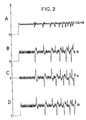
- FIG. 1 the current flowing before the switching from thyristor 1 to the thyristor 3 is shown by arrows in solid line and by arrows in dotted lines, the current flowing during switching.
- the ignition angle command a of the network bridge PRB is made so that the current IB rises as the current IA decreases so as to cancel the torque pulsation at the shaft of the synchronous machine.
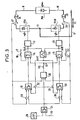
- FIG. 3 represents a diagram showing an embodiment of the control of the PRA and PRB bridges making it possible to obtain the result given above.
- the network bridges PRA and PRB each have an individual ignition control circuit 12, 13 respectively receiving a control voltage UcA, UcB supplied by summing circuits 14 and 15.
- the circuit 14 has three inputs, the first receives, via a door 16, a full inverter control signal from the PRA bridge, arriving on a conductor 17, the second receives the output signal from a regulator 18 of the current lA and the third is connected, via a gate 19, to a comparator circuit 20.
- the summing circuit 15 also has three inputs, the first by means of a gate 21, a signal of the full inverter control of the PRB bridge arriving on a conductor 22, the second receives the output signal from a regulator 23 of the current IB and the third is also connected to the comparator circuit 20 via the gate 19.
- the comparator 20 compares the sum of the currents lA + IB with an average current setpoint signal produced by a speed regulator 24.
- the output signal of the comparator 20 is proportional to the difference between this average current setpoint signal and the sum of the currents lA + IB.
- the speed regulator 24 generates its output signal from the measurement of the speed of the synchronous machine 7 from which an image signal of this speed is sent on an input 25 and from a speed reference signal produced by a circuit 26.
- the mean current setpoint signal produced by the speed regulator 24 is also sent to an input of the current regulator 18 of the current I which also receives a current measurement signal IA produced by a current reducer 27. These two signals are applied to regulator 18 by a door 28.
- the output signal from speed regulator 24 is also sent to an input of regulator 23 of current IB which also receives a measurement signal of current IB produced by a current reducer 29 These two signals are also applied to two inputs of the regulator 23 by a gate 30.
- the assembly also includes a comparator 31 giving an AUC signal sent on the one hand to a third input of the regulator 18 via a gate 32 and on the other hand to a third input of the regulator 23 via the 'through a gate 33.
- This signal AUC is proportional to the difference between the input signals: UcA and UcB collected at the output of the summing circuits 14 and 15.
- Doors 16, 19 and 30 are closed and doors 21, 28, 32 and 33 are open.
- the PRA bridge is controlled "full inverter” by sending the full inverter control signal, conductor 17, to an input of the summing circuit 14.
- the PRB bridge receives an additional instruction UC + coming from the comparator circuit 20, which controls a rise in the current IB compensating for the momentary disappearance of the current IA.
- the regulator 23 of the current IB is in operation, on the other hand the regulator 18 of the current IA is put out of operation by the opening of the door 28 of input of reference and current measurement.
- the regulator retains its output state preceding the instant of switching and resumes normal operation at the end of switching, the signal UcA at output of circuit 14 thus taking up the value it had at the time of the start of switching of the bridge.
- the setpoint Uc + is produced by the comparator 20 which compares the sum of the instantaneous currents IA + IB with the reference average current setpoint from circuit 24.
- the comparator circuit 31 In normal operation, that is to say in natural switching, apart from the clocked operation, the doors 32, 33, 28 and 30 are closed and all the others are open, the comparator circuit 31 then enters into service to force the operation with identical opening of the ignition angles of the PRA and PRB bridges, it is indeed generally not required, apart from the clocked operation, to control the two PRA and PRB bridges differently.
- the network bridge can be constituted by a single bridge and in the link 8 connects the neutral point of the synchronous machine to the neutral point of the secondary, mounted in a star, of the power transformer.
Landscapes
- Engineering & Computer Science (AREA)
- Power Engineering (AREA)
- Control Of Ac Motors In General (AREA)
- Control Of Eletrric Generators (AREA)
Applications Claiming Priority (2)
| Application Number | Priority Date | Filing Date | Title |
|---|---|---|---|
| FR8110613 | 1981-05-27 | ||
| FR8110613A FR2507025A1 (fr) | 1981-05-27 | 1981-05-27 | Dispositif de commande d'un convertisseur statique alternatif-alternatif a thyristors alimentant a frequence variable une machine tournante synchrone |
Publications (2)
| Publication Number | Publication Date |
|---|---|
| EP0066191A1 EP0066191A1 (fr) | 1982-12-08 |
| EP0066191B1 true EP0066191B1 (fr) | 1985-05-02 |
Family
ID=9258960
Family Applications (1)
| Application Number | Title | Priority Date | Filing Date |
|---|---|---|---|
| EP82104377A Expired EP0066191B1 (fr) | 1981-05-27 | 1982-05-19 | Dispositif de commande d'un convertisseur statique alternatif-alternatif à thyristors alimentant à fréquence variable une machine tournante synchrone |
Country Status (5)
| Country | Link |
|---|---|
| US (1) | US4424475A (OSRAM) |
| EP (1) | EP0066191B1 (OSRAM) |
| JP (1) | JPS57199497A (OSRAM) |
| DE (1) | DE3263363D1 (OSRAM) |
| FR (1) | FR2507025A1 (OSRAM) |
Families Citing this family (4)
| Publication number | Priority date | Publication date | Assignee | Title |
|---|---|---|---|---|
| FR2522217A1 (fr) * | 1982-02-19 | 1983-08-26 | Alsthom Cgee | Ensemble d'alimentation et de commande d'une machine tournante synchrone fonctionnant a vitesse variable |
| US4536692A (en) * | 1983-02-22 | 1985-08-20 | Cgee Alsthom | Circuit for energizing and controlling a synchronous rotary machine operating at variable speed |
| JP2533513B2 (ja) * | 1987-02-06 | 1996-09-11 | 株式会社日立製作所 | コンバ−タ回路の制御装置 |
| CN111384838B (zh) * | 2018-12-27 | 2023-05-16 | 核工业西南物理研究院 | 变频率同步信号实时追踪处理系统及方法 |
Family Cites Families (6)
| Publication number | Priority date | Publication date | Assignee | Title |
|---|---|---|---|---|
| DE2234681C3 (de) | 1972-07-14 | 1975-07-31 | Siemens Ag, 1000 Berlin Und 8000 Muenchen | Verfahren und Schaltungsanordnung zum Herabsetzen der Drehmomenten-Welligkeit einer Drehfeldmaschine |
| FR2385252A1 (fr) * | 1977-03-25 | 1978-10-20 | Alsthom Cgee | Convertisseur statique alternatif-alternatif a thyristors pour moteur synchrone auto-pilote |
| JPS5413919A (en) | 1977-07-04 | 1979-02-01 | Hitachi Ltd | Preventive controller for torque pulsation |
| SE415424B (sv) | 1978-12-28 | 1980-09-29 | Asea Ab | Drivutrustning innefattande en frekvensomriktarmatad tvafasig synkronmotor |
| US4274042A (en) * | 1979-04-24 | 1981-06-16 | General Electric Company | AC Motor drive system having clamped command error signal |
| JPS55143626A (en) | 1979-04-26 | 1980-11-10 | Toshiba Corp | Current control method of control rectifier |
-
1981
- 1981-05-27 FR FR8110613A patent/FR2507025A1/fr active Granted
-
1982
- 1982-05-13 JP JP57080812A patent/JPS57199497A/ja active Pending
- 1982-05-19 EP EP82104377A patent/EP0066191B1/fr not_active Expired
- 1982-05-19 DE DE8282104377T patent/DE3263363D1/de not_active Expired
- 1982-05-21 US US06/380,599 patent/US4424475A/en not_active Expired - Lifetime
Also Published As
| Publication number | Publication date |
|---|---|
| DE3263363D1 (en) | 1985-06-05 |
| FR2507025A1 (fr) | 1982-12-03 |
| US4424475A (en) | 1984-01-03 |
| FR2507025B1 (OSRAM) | 1984-07-13 |
| JPS57199497A (en) | 1982-12-07 |
| EP0066191A1 (fr) | 1982-12-08 |
Similar Documents
| Publication | Publication Date | Title |
|---|---|---|
| FR2486907A1 (fr) | Dispositif de generation d'energie electrique et de demarrage de moteur pour un aeronef | |
| FR2553600A1 (fr) | Onduleur utilisable avec des charges desequilibrees et a facteur de puissance variable | |
| EP0480846B1 (fr) | Installation d'alimentation en énergie électrique alternative comportant une alimentation de secours équipée d'un onduleur fontionnant en mode réversible | |
| EP0066191B1 (fr) | Dispositif de commande d'un convertisseur statique alternatif-alternatif à thyristors alimentant à fréquence variable une machine tournante synchrone | |
| EP0147280B1 (fr) | Procédé et dispositif d'alimentation d'une charge notamment un moteur à courant continu pour locomotives ferroviaires du type bi-courant | |
| FR2618276A1 (fr) | Dispositif de commutation electronique. | |
| FR2999357A1 (fr) | Chaine d'entrainement electrique d'un dispositif, et equipement de compression de gaz comprenant une telle chaine | |
| EP0289373A1 (fr) | Convertisseur à modulation de largeur d'impulsions | |
| CA2215181A1 (fr) | Convertisseur de puissance a commutation douce comprenant des moyens de correction de la tension mediane d'un diviseur de tension capacitif | |
| EP0087115B1 (fr) | Ensemble d'alimentation et de commande d'une machine tournante synchrone fonctionnant à vitesse variable | |
| EP0926807A1 (fr) | Convertisseur alternatif-continu triphasé | |
| CH619573A5 (OSRAM) | ||
| FR2613551A1 (fr) | Dispositif automatique de correction de l'ordre de succession des phases de l'alimentation triphasee d'une installation electrique | |
| EP0267252B1 (fr) | Convertisseur de frequence pour l'alimentation stabilisee de moteurs asynchrones | |
| FR2901431A1 (fr) | Circuit de conversion de courant. | |
| FR2778286A1 (fr) | Circuit convertisseur de tension | |
| EP0120749B1 (fr) | Procédé et dispositif de mesure du glissement d'un moteur | |
| FR2465361A1 (fr) | Circuit d'alimentation controle a courant continu a recuperation | |
| FR2992686A1 (fr) | Dispositif d'inversion de poussee pour un aeronef comprenant au moins deux inverseurs de poussee | |
| FR2459580A1 (fr) | Dispositif de synchronisation pour la commutation d'un moteur electrique entre deux sources d'alimentation | |
| FR2721770A1 (fr) | Procédé de commande d'un gradateur de tension pour l'alimentation d'un moteur à induction. | |
| FR2598567A1 (fr) | Procede et dispositif de commande d'un onduleur connecte a une charge polyphasee | |
| FR2543759A1 (fr) | Dispositif de commutation statique traction-freinage pour systeme a vitesse variable a moteurs asynchrones alimentes par commutateur de courant | |
| EP4418527A1 (fr) | Procédé et système de contrôle de la connexion d'une machine électrique à un réseau électrique via un contacteur de bypass | |
| FR2737946A1 (fr) | Dispositif de commande de l'alimentation d'une machine electrique |
Legal Events
| Date | Code | Title | Description |
|---|---|---|---|
| PUAI | Public reference made under article 153(3) epc to a published international application that has entered the european phase |
Free format text: ORIGINAL CODE: 0009012 |
|
| AK | Designated contracting states |
Designated state(s): CH DE FR GB SE |
|
| 17P | Request for examination filed |
Effective date: 19830530 |
|
| GRAA | (expected) grant |
Free format text: ORIGINAL CODE: 0009210 |
|
| AK | Designated contracting states |
Designated state(s): CH DE FR GB LI SE |
|
| REF | Corresponds to: |
Ref document number: 3263363 Country of ref document: DE Date of ref document: 19850605 |
|
| PLBE | No opposition filed within time limit |
Free format text: ORIGINAL CODE: 0009261 |
|
| STAA | Information on the status of an ep patent application or granted ep patent |
Free format text: STATUS: NO OPPOSITION FILED WITHIN TIME LIMIT |
|
| 26N | No opposition filed | ||
| EAL | Se: european patent in force in sweden |
Ref document number: 82104377.5 |
|
| PGFP | Annual fee paid to national office [announced via postgrant information from national office to epo] |
Ref country code: GB Payment date: 20010412 Year of fee payment: 20 |
|
| PGFP | Annual fee paid to national office [announced via postgrant information from national office to epo] |
Ref country code: CH Payment date: 20010418 Year of fee payment: 20 |
|
| PGFP | Annual fee paid to national office [announced via postgrant information from national office to epo] |
Ref country code: SE Payment date: 20010503 Year of fee payment: 20 |
|
| PGFP | Annual fee paid to national office [announced via postgrant information from national office to epo] |
Ref country code: FR Payment date: 20010507 Year of fee payment: 20 |
|
| PGFP | Annual fee paid to national office [announced via postgrant information from national office to epo] |
Ref country code: DE Payment date: 20010509 Year of fee payment: 20 |
|
| REG | Reference to a national code |
Ref country code: GB Ref legal event code: IF02 |
|
| PG25 | Lapsed in a contracting state [announced via postgrant information from national office to epo] |
Ref country code: LI Free format text: LAPSE BECAUSE OF EXPIRATION OF PROTECTION Effective date: 20020518 Ref country code: GB Free format text: LAPSE BECAUSE OF EXPIRATION OF PROTECTION Effective date: 20020518 Ref country code: CH Free format text: LAPSE BECAUSE OF EXPIRATION OF PROTECTION Effective date: 20020518 |
|
| REG | Reference to a national code |
Ref country code: GB Ref legal event code: PE20 Effective date: 20020518 |
|
| REG | Reference to a national code |
Ref country code: CH Ref legal event code: PL |
|
| EUG | Se: european patent has lapsed |
Ref document number: 82104377.5 |