EP0065625A2 - A capacitive transducer for providing precise angular position information - Google Patents
A capacitive transducer for providing precise angular position information Download PDFInfo
- Publication number
- EP0065625A2 EP0065625A2 EP82101680A EP82101680A EP0065625A2 EP 0065625 A2 EP0065625 A2 EP 0065625A2 EP 82101680 A EP82101680 A EP 82101680A EP 82101680 A EP82101680 A EP 82101680A EP 0065625 A2 EP0065625 A2 EP 0065625A2
- Authority
- EP
- European Patent Office
- Prior art keywords
- track
- stator
- tracks
- segments
- rotor
- Prior art date
- Legal status (The legal status is an assumption and is not a legal conclusion. Google has not performed a legal analysis and makes no representation as to the accuracy of the status listed.)
- Granted
Links
Images


Classifications
-
- G—PHYSICS
- G01—MEASURING; TESTING
- G01D—MEASURING NOT SPECIALLY ADAPTED FOR A SPECIFIC VARIABLE; ARRANGEMENTS FOR MEASURING TWO OR MORE VARIABLES NOT COVERED IN A SINGLE OTHER SUBCLASS; TARIFF METERING APPARATUS; MEASURING OR TESTING NOT OTHERWISE PROVIDED FOR
- G01D5/00—Mechanical means for transferring the output of a sensing member; Means for converting the output of a sensing member to another variable where the form or nature of the sensing member does not constrain the means for converting; Transducers not specially adapted for a specific variable
- G01D5/12—Mechanical means for transferring the output of a sensing member; Means for converting the output of a sensing member to another variable where the form or nature of the sensing member does not constrain the means for converting; Transducers not specially adapted for a specific variable using electric or magnetic means
- G01D5/14—Mechanical means for transferring the output of a sensing member; Means for converting the output of a sensing member to another variable where the form or nature of the sensing member does not constrain the means for converting; Transducers not specially adapted for a specific variable using electric or magnetic means influencing the magnitude of a current or voltage
- G01D5/24—Mechanical means for transferring the output of a sensing member; Means for converting the output of a sensing member to another variable where the form or nature of the sensing member does not constrain the means for converting; Transducers not specially adapted for a specific variable using electric or magnetic means influencing the magnitude of a current or voltage by varying capacitance
- G01D5/241—Mechanical means for transferring the output of a sensing member; Means for converting the output of a sensing member to another variable where the form or nature of the sensing member does not constrain the means for converting; Transducers not specially adapted for a specific variable using electric or magnetic means influencing the magnitude of a current or voltage by varying capacitance by relative movement of capacitor electrodes
- G01D5/2412—Mechanical means for transferring the output of a sensing member; Means for converting the output of a sensing member to another variable where the form or nature of the sensing member does not constrain the means for converting; Transducers not specially adapted for a specific variable using electric or magnetic means influencing the magnitude of a current or voltage by varying capacitance by relative movement of capacitor electrodes by varying overlap
- G01D5/2415—Mechanical means for transferring the output of a sensing member; Means for converting the output of a sensing member to another variable where the form or nature of the sensing member does not constrain the means for converting; Transducers not specially adapted for a specific variable using electric or magnetic means influencing the magnitude of a current or voltage by varying capacitance by relative movement of capacitor electrodes by varying overlap adapted for encoders
Definitions
- This invention relates to angular position sensing transducers and more particularly to capacitive position sensing transducers.
- Angular shaft position sensing devices have been extensively used for many years. Traditionally, such position sensing transducers have been either magnetic sensing transducers or optical sensing transducers. However, in the past decade, capacitive position sensing transducers have been increasing in interest to the art. Capacitive transducers have been less sensitive to stray noise than either magnetic or optical transducers. Unlike the optical transducer, the capacitive transducers are not sensitive to ambient light and unlike the magnetic transducer, the capacitive transducer is not sensitive to stray magnetic fields. In addition, the capacitive transducer is less sensitive to the effects of accumulated dust than the other transducers. Capacitive transducers are lower in cost than optical transducers.
- a plurality of conductive segments in a movable element i.e., the rotor coact with a plurality of conductive segments on a stationary element, i.e., the stator spaced from the movable element to produce the output pulses indicative of the velocity and the position of the movable element.
- the repetitive patterns of conductive elements both on the stator and rotor have been substantially rectangular in shape. This has produced sensed output pulses which are also substantially rectangular. With such rectangular, e.g., square wave pulses, the preciseness of the angular position being sensed is limited since all position along a particular elevated segment or depressed segment in the square or rectangular wave will produce the same signal.
- the description of the conductive segments on the rotor and/or stator as substantially rectangular is meant to include patterns in which each of the segments has two sides formed along radii through the axis of rotation of the rotor. Patterns of such conductive segments, a wide variety of which are set forth in U.S. Patent 3,222,668, "Capacitive Coder", B. Lippel, issued Dec. 7, 1965, will produce a substantially rectangular or square waveform, i.e., produce waveforms which have two clearly distinct states. Thus, they are in effect digital signals.
- the present invention provides an expedient wherein pulses produced can be tailored into virtually any predetermined shape by varying the shape of the repetitive segment on either the stator or rotor in preselected non-rectangular patterns.
- the resulting signal will have a waveform of varying shape. It will be essentially analog in characteristics.
- the present invention provides a capacitive transducer wherein angular positions and consequently angular velocities may be more precisely sensed through the production of transducer output signal patterns which are non-rectangular in shape.
- the capacitive transducer comprises a first member having a first track of spaced repetitive conductive segments and a second member having a second track of spaced repetitive conductive segments spaced from and facing the first track. Means are provided for moving one of said members with respect to the other whereby the track on the moving member rotates with respect to the track on the other member.
- Means are provided for applying an alternating electrical signal to the first of said tracks of repetitive conductive segments and means are connected to the second track of repetitive conductive segments for sensing the electrical signal induced in the second track by said capacitive effect.
- At least one of the tracks has repetitive segments having shapes other than rectangular shapes; this will result in a transducer output waveform of a non-rectangular shape.
- the transducer has the capability of producing a continuously varying waveform, i.e., analog waveform as opposed to the more conventional prior art waveform which was square or rectangular wave, i.e., digital waveform.
- the continuously varying waveform produced by the transducer of the present invention it becomes possible to more precisely find the angular position of a rotating shaft at any specific point in time.
- the first and second members are embodied by the conventional capacitive transducer rotor and stator members.
- the non-rectangular segments may desirably be triangular in shape or even combine to form a sinusoidal pattern.
- the transducer of the present invention produces output patterns which are continuously varying as opposed to more conventional transducers which produce square or rectangular wave patterns wherein all of the positions along a particular elevated wave segment or depressed wave segments will provide the same signal level.
- a continuously varying signal produced by the transducer of the present invention it is possible to more precisely define angular positions since every position along the wave produces a signal level different from its adjacent positions.
- rotatable shaft 10 has rotor 11 mounted thereon so that shaft 10 of rotor 11 rotates with respect to stator 12 which is affixed to frame 13 of the equipment.
- Stator 12 contains two tracks 14 and 15 of electrically conductive segments 16 and 16'. The segments in each of the tracks are connected to each other.
- the rotor 11 contains two concentric annular conductive plates 17 and 18. A radial array of fingers 19 extend from conductive plate 17 and a second radial array of conductive fingers 19' extend from conductive plate 18.
- the purpose of using two tracks 14 and 15 of conductive segments is to produce two different signals which may be used for two different phases of a stepper motor drive. Any number of tracks could be used, e.g., for a three phase stepper motor drive, three tracks could be used.
- oscillator 20 produces an alternating output on line 21 which is applied to annular conductive plate 22 on the stator.
- inverter 24 inverts the alternating output from oscillator 20 on line 21, i.e., brings it 180° out of phase and applies that output via line 25 to annular conductive plate 23.
- the alternating signals on lines 21 and 25, respectively designated Einl and Ein2, are shown in the timing chart in Fig. 4. It should be noted that the oscillator output on line 21 (Einl) is to be applied to fingers 19 of the rotor while the inverted oscillator output (Ein2) on line 25 is to be applied to fingers 19' on the rotor.
- Finger array 19 is capacitively coupled to the conductive segments 16 and 16' in both tracks 14 and 15. Also, finger array 19' in the rotor is capacitively coupled to conductive segments 16 and 16' in both tracks 14 and 15. Conductive segments 16' in track 15 are arranged so that they are spacially 90° out of phase with conductive segments 16 in track 14.
- the output from track 15, designated Etl is applied on line 26 to amplifier 27 while the output of track 14, designated Et2, is applied via line 28 to amplifier 29.
- Etl and Et2 have the waveforms shown in Fig. 4.
- the outputs of amplifiers 27 and 29 are respectively applied to demodulators 30 and 31.
- waveforms Eoutl and Eout2 are in effect respectively the demodulated envelopes of the amplified waveforms Etl and Et2 which are applied to amplifiers 27 and 29. Since segments in tracks 14 and 15 were 90° out of phase, waveforms Eoutl and Eout2 are also 90° out of phase with each other.
- Some typical operational parameters which may be used in connection with structure and circuitry described above are rotor rotating at about 20 rps, and oscillator 20 output having a voltage swing of 12 volts at a frequency of 1 MHz and an amplifier which provides an amplified output yielding a demodulated envelope having a voltage swing of 2 volts.
- the air gap between the stator and rotor is in the order of from .005 to .05 inches.
- stator plate 23 and rotor plate 18 of Fig. 1 have identical circular shapes and dimensions. A relatively large and constant capacitance exists between them as the rotor turns with respect to the stator. Similarly, a relatively large and constant capacitance exists between plates 17 and 22.
- the high frequency modulating signals, Einl and Ein2 are applied to plates 22 and 23, respectively, and because of the large and unvarying capacitive couplings, the Einl and Ein2 waveforms appear to rotor plates 17 and 18, respectively.
- the rotor and stator patterns and circuitry described above provide an invention which is based upon the tailoring of the conductive segments in the stator in a non-rectangular form.
- By thus tailoring stator tracks it is possible to produce a waveform configuration from the transducer which has any desired form, e.g., it may be triangular or even sinusoidal. With such a capability, the waveform from the transducer yields more precise positional and consequently velocity data.
- the rotor and stator patterns shown in Figs. 1 and 2 produce waveforms that are independent of the direction of rotor rotation. These waveforms are adequate for some types of stepper motor controllers. If waveforms are desired which are different depending on the direction of rotation and which allow more precise bidirectional control, then a somewhat more sophisticated stator pattern as shown in Fig. 6 should be used.
- the rotor associated with the stator in Fig. 6 has the conductive pattern shown in Fig. 5. Without going into the operation, the patterns and circuitry for transducer having the rotor and stator patterns respectively shown in Figs. 5 and 6 will now be described.
- the output of oscillator 53 is inverted in inverter 54 and applied to conductive segments in tracks 41 and 44.
- conductive fingers 55 which extend from annular plate 57 rotate across tracks 41 and 42 in the stator while conductive fingers 56 which extend from annular plate 58 rotate across tracks 43 and 44 in the stator.
- the output from fingers 55 is applied via annular plate 57, which is capacitively coupled to annular plate 59 in the stator, through line 61 to amplifier 62 while the output sensed by fingers 56 in the rotor are applied via annular plate 58, which is capacitively coupled to annular plate 60 in the stator, through line 63 to amplifier 64.
Landscapes
- Engineering & Computer Science (AREA)
- Power Engineering (AREA)
- Physics & Mathematics (AREA)
- General Physics & Mathematics (AREA)
- Transmission And Conversion Of Sensor Element Output (AREA)
- Measurement Of Length, Angles, Or The Like Using Electric Or Magnetic Means (AREA)
Abstract
Description
- This invention relates to angular position sensing transducers and more particularly to capacitive position sensing transducers.
- Angular shaft position sensing devices have been extensively used for many years. Traditionally, such position sensing transducers have been either magnetic sensing transducers or optical sensing transducers. However, in the past decade, capacitive position sensing transducers have been increasing in interest to the art. Capacitive transducers have been less sensitive to stray noise than either magnetic or optical transducers. Unlike the optical transducer, the capacitive transducers are not sensitive to ambient light and unlike the magnetic transducer, the capacitive transducer is not sensitive to stray magnetic fields. In addition, the capacitive transducer is less sensitive to the effects of accumulated dust than the other transducers. Capacitive transducers are lower in cost than optical transducers.
- Some representative prior art description of capacitive transducer technology may be found in the following:
- "Dual Plane Capacitive Coupling Encoder" authored by R. J. Flaherty, M. L. Sendelweck, and J. W. Woods, IBM Technical Disclosure Bulletin, Vol. 15, Nov. 4, Sept. 1972.
- "Electrodynamic Velocity and Position Sensor and Emitter Wheel", authored by H. E. Naylor, III, and R. A. Williams, IBM Technical Disclosure Bulletin, Vol. 16, No. 10, March 1974.
- "Trapped Charge Transducer for Low-Cost Angular Position Sensing", authored by J. M. Rakes and E. R. Williams, IBM Technical Disclosure Bulletin, Vol. 23, No. 11, April 1981.
- U.S. Patent 3,702,467, "Shaft Position Sensing Device", George Melnyk, Issued Nov. 7, 1972.
- U.S. Patent 3,938,113, "Differential Capacitive Position Encoder", D. R. Dobson et al, Issued Feb. 10, 1976.
- U.S. Patent 4,040,041, "Twin-Capacitive Shaft Angle Encoder with Analog Output Signal", J. C. Fletcher et al, Issued Aug. 2, 1977.
- In conventional capacitive transducers of the group illustrated above, a plurality of conductive segments in a movable element, i.e., the rotor coact with a plurality of conductive segments on a stationary element, i.e., the stator spaced from the movable element to produce the output pulses indicative of the velocity and the position of the movable element. In standard capacitive transducer technology, the repetitive patterns of conductive elements both on the stator and rotor have been substantially rectangular in shape. This has produced sensed output pulses which are also substantially rectangular. With such rectangular, e.g., square wave pulses, the preciseness of the angular position being sensed is limited since all position along a particular elevated segment or depressed segment in the square or rectangular wave will produce the same signal.
- The description of the conductive segments on the rotor and/or stator as substantially rectangular is meant to include patterns in which each of the segments has two sides formed along radii through the axis of rotation of the rotor. Patterns of such conductive segments, a wide variety of which are set forth in U.S. Patent 3,222,668, "Capacitive Coder", B. Lippel, issued Dec. 7, 1965, will produce a substantially rectangular or square waveform, i.e., produce waveforms which have two clearly distinct states. Thus, they are in effect digital signals.
- The present invention provides an expedient wherein pulses produced can be tailored into virtually any predetermined shape by varying the shape of the repetitive segment on either the stator or rotor in preselected non-rectangular patterns. The resulting signal will have a waveform of varying shape. It will be essentially analog in characteristics.
- The present invention provides a capacitive transducer wherein angular positions and consequently angular velocities may be more precisely sensed through the production of transducer output signal patterns which are non-rectangular in shape. The capacitive transducer comprises a first member having a first track of spaced repetitive conductive segments and a second member having a second track of spaced repetitive conductive segments spaced from and facing the first track. Means are provided for moving one of said members with respect to the other whereby the track on the moving member rotates with respect to the track on the other member. Means are provided for applying an alternating electrical signal to the first of said tracks of repetitive conductive segments and means are connected to the second track of repetitive conductive segments for sensing the electrical signal induced in the second track by said capacitive effect. At least one of the tracks has repetitive segments having shapes other than rectangular shapes; this will result in a transducer output waveform of a non-rectangular shape. By tailoring the shape of the non-rectangular segments a wide variety of transducer output waveform shapes may be produced. Thus, the transducer has the capability of producing a continuously varying waveform, i.e., analog waveform as opposed to the more conventional prior art waveform which was square or rectangular wave, i.e., digital waveform. With the continuously varying waveform produced by the transducer of the present invention, it becomes possible to more precisely find the angular position of a rotating shaft at any specific point in time.
- Preferably, the first and second members are embodied by the conventional capacitive transducer rotor and stator members. The non-rectangular segments may desirably be triangular in shape or even combine to form a sinusoidal pattern.
- Accordingly, the transducer of the present invention produces output patterns which are continuously varying as opposed to more conventional transducers which produce square or rectangular wave patterns wherein all of the positions along a particular elevated wave segment or depressed wave segments will provide the same signal level. With a continuously varying signal produced by the transducer of the present invention, it is possible to more precisely define angular positions since every position along the wave produces a signal level different from its adjacent positions.
- Referring now to the drawings, wherein a preferred embodiment of the invention is illustrated, and wherein like reference numerals are used throughout to designate like parts;
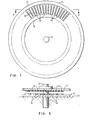
- Fig. 1 is a diagrammatic plan view of the planar surface on the rotor which forms a portion of the transducer of the present invention.
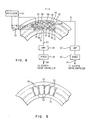
- Fig. 2 is a diagrammatic plan view of the stator surface containing two tracks of conductive non-rectangular segments forming another portion of the transducer together with a circuit logic drawing of the circuitry necessary to provide the other alternating signal and to monitor the induced capacitive effect.
- Fig. 3 is an enlarged fragmentary sectional side view showing the rotor and stator of Figs. 1 and 2 mounted on a shaft to illustrate relative positions of the conductive segments in the rotor and stator.
- Fig. 4 is a timing chart showing the electrical output of the circuit logic elements in Fig. 2 relative to the rotational shaft position.
- Fig. 5 is a diagrammatic plan view of a portion of the planar surface on the rotor in accordance with another aspect of the present invention.
- Fig. 6 is a diagrammatic plan view of a portion of the stator surface which together with the rotor shown in Fig. 5 forms a transducer.
- With reference to Figs. 1, 2 and 3, in the preferred embodiment of the present invention,
rotatable shaft 10 hasrotor 11 mounted thereon so thatshaft 10 ofrotor 11 rotates with respect tostator 12 which is affixed toframe 13 of the equipment.Stator 12 contains twotracks 14 and 15 of electricallyconductive segments 16 and 16'. The segments in each of the tracks are connected to each other. Therotor 11 contains two concentric annularconductive plates fingers 19 extend fromconductive plate 17 and a second radial array of conductive fingers 19' extend fromconductive plate 18. - As will be described hereinafter in greater detail, the purpose of using two
tracks 14 and 15 of conductive segments is to produce two different signals which may be used for two different phases of a stepper motor drive. Any number of tracks could be used, e.g., for a three phase stepper motor drive, three tracks could be used. - Considering now the operation of the transducer of the present invention,
oscillator 20 produces an alternating output online 21 which is applied to annularconductive plate 22 on the stator. In addition,inverter 24 inverts the alternating output fromoscillator 20 online 21, i.e., brings it 180° out of phase and applies that output vialine 25 to annularconductive plate 23. The alternating signals onlines fingers 19 of the rotor while the inverted oscillator output (Ein2) online 25 is to be applied to fingers 19' on the rotor. Since it is conventional practice not to couple any lines directly to the rotor on the rotating shaft, respective oscillator outputs described are applied tofingers 19 and 19' through capacitive coupling respectively provided byannular plate 22 on the stator which is capacitively coupled toannular plate 17 on the rotor andannular plate 23 on the stator which is capacitively coupled toannular plate 18 on the rotor. The areas of these two pairs capacitive coupled plates is so substantial in relation to the spacing between the coupled plates that the amplitude of the oscillator output being respectively applied tofingers 19 and 19' is only minimally diminished. -
Finger array 19 is capacitively coupled to theconductive segments 16 and 16' in bothtracks 14 and 15. Also, finger array 19' in the rotor is capacitively coupled toconductive segments 16 and 16' in bothtracks 14 and 15. Conductive segments 16' intrack 15 are arranged so that they are spacially 90° out of phase withconductive segments 16 in track 14. The output fromtrack 15, designated Etl, is applied online 26 toamplifier 27 while the output of track 14, designated Et2, is applied vialine 28 toamplifier 29. Etl and Et2 have the waveforms shown in Fig. 4. The outputs ofamplifiers demodulators demodulators lines amplifiers tracks 14 and 15 were 90° out of phase, waveforms Eoutl and Eout2 are also 90° out of phase with each other. - Some typical operational parameters which may be used in connection with structure and circuitry described above are rotor rotating at about 20 rps, and
oscillator 20 output having a voltage swing of 12 volts at a frequency of 1 MHz and an amplifier which provides an amplified output yielding a demodulated envelope having a voltage swing of 2 volts. The air gap between the stator and rotor is in the order of from .005 to .05 inches. - In order to promote a better understanding of the principles involved in the present invention, the following theory is offered as to how waveform Etl on
line 26 shown in Fig. 4 results. Of course, the theory will be equally applicable to waveform Et2 online 28. - The annular portion of
stator plate 23 androtor plate 18 of Fig. 1 have identical circular shapes and dimensions. A relatively large and constant capacitance exists between them as the rotor turns with respect to the stator. Similarly, a relatively large and constant capacitance exists betweenplates plates rotor plates - As shown in Fig. 4, Einl and Ein2 are identical but opposite in phase. As
rotor fingers 19 and 19' move over segments 16', the voltage Etl induced ontrack 15 can be shown to be
segment array 19 andtrack 15, and C2 is the varying capacitance between segment array 19' andtrack 15. Since capacitances Cl and C2 vary directly with the area oftrack 15 immediately underfingers 19 and 19', respectively, the induced waveform Etl is determined by the shape of segments 16'. - The rotor and stator patterns and circuitry described above provide an invention which is based upon the tailoring of the conductive segments in the stator in a non-rectangular form. By thus tailoring stator tracks, it is possible to produce a waveform configuration from the transducer which has any desired form, e.g., it may be triangular or even sinusoidal. With such a capability, the waveform from the transducer yields more precise positional and consequently velocity data.
- The rotor and stator patterns shown in Figs. 1 and 2 produce waveforms that are independent of the direction of rotor rotation. These waveforms are adequate for some types of stepper motor controllers. If waveforms are desired which are different depending on the direction of rotation and which allow more precise bidirectional control, then a somewhat more sophisticated stator pattern as shown in Fig. 6 should be used. The rotor associated with the stator in Fig. 6 has the conductive pattern shown in Fig. 5. Without going into the operation, the patterns and circuitry for transducer having the rotor and stator patterns respectively shown in Figs. 5 and 6 will now be described. It will be obvious to one skilled in the art in light of the operations described above how such a transducer can be used to provide two phase output to stepper motor control circuitry when the shaft is respectively rotating in both the clockwise and counterclockwise directions. There are four
tracks oscillator 53 is applied directly to conductive segments intracks oscillator 53 is inverted ininverter 54 and applied to conductive segments intracks conductive fingers 55 which extend fromannular plate 57 rotate acrosstracks conductive fingers 56 which extend fromannular plate 58 rotate acrosstracks fingers 55 is applied viaannular plate 57, which is capacitively coupled toannular plate 59 in the stator, throughline 61 toamplifier 62 while the output sensed byfingers 56 in the rotor are applied viaannular plate 58, which is capacitively coupled toannular plate 60 in the stator, throughline 63 toamplifier 64. These outputs are consequently amplified and respectively demodulated throughdemodulators lines - While the invention has been particularly shown and described with reference to a preferred embodiment it will be understood by those skilled in the art that various other changes in form and detail may be made without departing from the spirit and scope of the invention.
Claims (10)
characterized in that :
Applications Claiming Priority (2)
| Application Number | Priority Date | Filing Date | Title |
|---|---|---|---|
| US261401 | 1981-05-07 | ||
| US06/261,401 US4404560A (en) | 1981-05-07 | 1981-05-07 | Capacitive transducer for providing precise angular positional information |
Publications (3)
| Publication Number | Publication Date |
|---|---|
| EP0065625A2 true EP0065625A2 (en) | 1982-12-01 |
| EP0065625A3 EP0065625A3 (en) | 1985-05-22 |
| EP0065625B1 EP0065625B1 (en) | 1989-05-31 |
Family
ID=22993146
Family Applications (1)
| Application Number | Title | Priority Date | Filing Date |
|---|---|---|---|
| EP82101680A Expired EP0065625B1 (en) | 1981-05-07 | 1982-03-04 | A capacitive transducer for providing precise angular position information |
Country Status (4)
| Country | Link |
|---|---|
| US (1) | US4404560A (en) |
| EP (1) | EP0065625B1 (en) |
| JP (1) | JPS57182614A (en) |
| DE (1) | DE3279735D1 (en) |
Cited By (8)
| Publication number | Priority date | Publication date | Assignee | Title |
|---|---|---|---|---|
| GB2133889A (en) * | 1983-01-19 | 1984-08-01 | Lucas Ind Plc | Capacitance displacement transducers |
| GB2139359A (en) * | 1983-05-02 | 1984-11-07 | Computer Memories Inc | Capacitive position encoder |
| EP0226716A2 (en) * | 1985-09-16 | 1987-07-01 | Hewlett-Packard Company | Capacitive position transducer system |
| EP0248165A2 (en) * | 1986-04-04 | 1987-12-09 | Mitutoyo Corporation | Capacitance-type transducer for measuring positions |
| EP0435429A1 (en) * | 1989-10-10 | 1991-07-03 | Mitutoyo Corporation | Method and apparatus for simultaneous sensing of angular and axial position |
| US5239307A (en) * | 1989-10-10 | 1993-08-24 | Micro Encoder Inc. | Method and apparatus for sensing of position |
| US5513539A (en) * | 1994-06-30 | 1996-05-07 | Transalta Utilities Corporation | Apparatus and method for determining the best position for inner and outer members in a rotary machine |
| US5798999A (en) * | 1991-12-23 | 1998-08-25 | Nimbus Communications International Limited | Damped turntable/disk arculately positionable relative to a head |
Families Citing this family (24)
| Publication number | Priority date | Publication date | Assignee | Title |
|---|---|---|---|---|
| US4499465A (en) * | 1981-03-18 | 1985-02-12 | Nippon Soken, Inc. | Capacitive-type incremental and reference angular rotation detecting apparatus |
| EP0073903B1 (en) * | 1981-09-04 | 1986-10-01 | Contraves Ag | Arrangement for the contactless information transmission between bodies rotating relatively to one another |
| CH658556A5 (en) * | 1982-12-02 | 1986-11-14 | Studer Willi | SPEED-ACTUAL VALUE CONVERTER FOR SPEED CONTROL IN A MOTOR DRIVE SYSTEM. |
| US4879508A (en) * | 1986-04-04 | 1989-11-07 | Mitutoyo Corporation | Capacitance-type measuring device for absolute measurement of positions |
| US4893071A (en) * | 1988-05-24 | 1990-01-09 | American Telephone And Telegraph Company, At&T Bell Laboratories | Capacitive incremental position measurement and motion control |
| DE3904017A1 (en) * | 1989-02-10 | 1990-08-16 | Hofmann Gmbh & Co Kg Maschinen | MONITORING DEVICE FOR A BELT DRIVE |
| US5414420A (en) * | 1992-03-23 | 1995-05-09 | Hewlett-Packard Corporation | Switch interconnect for position encoder system |
| US5428355A (en) * | 1992-03-23 | 1995-06-27 | Hewlett-Packard Corporation | Position encoder system |
| US5681990A (en) * | 1995-12-07 | 1997-10-28 | Ford Motor Company | Capacitive throttle position sensor |
| US6492911B1 (en) | 1999-04-19 | 2002-12-10 | Netzer Motion Sensors Ltd. | Capacitive displacement encoder |
| US6211641B1 (en) * | 1999-05-12 | 2001-04-03 | Trw Inc. | Capacitive resolver |
| US6327327B1 (en) * | 1999-09-27 | 2001-12-04 | Picker International, Inc. | Multi-channel segmented slip ring |
| US6587093B1 (en) * | 1999-11-04 | 2003-07-01 | Synaptics Incorporated | Capacitive mouse |
| DE10039217A1 (en) * | 2000-08-11 | 2002-02-28 | Bosch Gmbh Robert | Device and method for contactless detection of an angle of rotation or a torsion twist |
| DE10048881A1 (en) * | 2000-09-29 | 2002-03-07 | Infineon Technologies Ag | Device for planar joining of two wafers e.g. for thin grinding and separation of product-wafer, has product wafer arranged surface-congruently over carrier wafer |
| US7071591B2 (en) * | 2003-01-02 | 2006-07-04 | Covi Technologies | Electromagnetic circuit and servo mechanism for articulated cameras |
| US20040169434A1 (en) * | 2003-01-02 | 2004-09-02 | Washington Richard G. | Slip ring apparatus |
| US20060176189A1 (en) * | 2005-02-06 | 2006-08-10 | David Bar-On | Two Dimensional Layout, High Noise Immunity, Interleaved Channels Electrostatic Encoder |
| US9092082B2 (en) | 2010-12-22 | 2015-07-28 | Synaptics Incorporated | Methods and apparatus for mounting a touch sensor device |
| JP5880884B2 (en) | 2013-05-31 | 2016-03-09 | 株式会社デンソー | Rotation state detection device |
| JP6507347B2 (en) * | 2014-07-30 | 2019-05-08 | 栃木県 | Capacitance type angle detector |
| DE102015121423A1 (en) * | 2015-12-09 | 2017-06-14 | Sick Ag | Apparatus for the contactless transmission of data and for determining an angle change between two relatively moving objects |
| US10908361B2 (en) | 2018-06-06 | 2021-02-02 | Apple Inc. | Capacitive position sensing for capacitive drive MEMS devices |
| US11715587B2 (en) * | 2019-05-24 | 2023-08-01 | Honeywell International Inc. | Rotary variable differential transformer |
Citations (9)
| Publication number | Priority date | Publication date | Assignee | Title |
|---|---|---|---|---|
| DE1248962B (en) * | 1967-08-31 | Sogemque (Electronics) Limited Newport Pagnell Buckinghamshire (Großbritannien) | Capacitive transmitter | |
| DE1290345B (en) * | 1967-02-08 | 1969-03-06 | Continental Elektronidustrie A | Transmitter for angular position measurement |
| DE1423823B1 (en) * | 1961-02-21 | 1971-06-03 | Telecomputing Corp | CAPACITIVE TRANSMITTER |
| DE2306752B1 (en) * | 1972-09-07 | 1974-03-28 | Maag-Zahnräder & - Maschinen AG, Zürich (Schweiz) | DEVICE FOR THE CAPACITIVE SCANNING OF CIRCULAR AND LENGTH DIVISIONS |
| DE2601088A1 (en) * | 1975-01-17 | 1976-07-22 | Farrand Ind Inc | POSITION MEASUREMENT CONVERTER |
| DE2429136B2 (en) * | 1974-06-18 | 1977-02-24 | Scheck, Werner, DipL-Phys., 5170Jülich | DEVICE FOR MEASURING LENGTH OR ANGLE |
| FR2411391A1 (en) * | 1977-12-09 | 1979-07-06 | Stiftelsen Inst Mikrovags | CAPACITIVE MEASUREMENT DEVICE |
| DE3013284A1 (en) * | 1979-04-09 | 1980-10-30 | Facom | DEVICE FOR MEASURING THE RELATIVE POSITION OF TWO OBJECTS TO ANOTHER BY CHANGING CAPACITY |
| DE3022956A1 (en) * | 1979-07-02 | 1981-01-15 | Nippon Soken | MEASURING DEVICE FOR DETECTING AND MONITORING ROTATIONAL MOTIONS |
Family Cites Families (7)
| Publication number | Priority date | Publication date | Assignee | Title |
|---|---|---|---|---|
| US3068457A (en) * | 1957-11-01 | 1962-12-11 | Telecomputing Corp | Displacement measuring device |
| US3348133A (en) * | 1962-10-25 | 1967-10-17 | Sogenique Electronics Ltd | Position responsive apparatus including a capacitive potentiometer |
| US3702467A (en) * | 1971-11-23 | 1972-11-07 | Ibm | Shaft position sensing device |
| JPS5149421B2 (en) * | 1972-07-24 | 1976-12-27 | ||
| US3938113A (en) * | 1974-06-17 | 1976-02-10 | International Business Machines Corporation | Differential capacitive position encoder |
| US4040041A (en) * | 1975-10-24 | 1977-08-02 | Nasa | Twin-capacitive shaft angle encoder with analog output signal |
| JPS5828526B2 (en) * | 1978-12-27 | 1983-06-16 | 株式会社日本自動車部品総合研究所 | rotation detection device |
-
1981
- 1981-05-07 US US06/261,401 patent/US4404560A/en not_active Expired - Fee Related
-
1982
- 1982-01-20 JP JP57006184A patent/JPS57182614A/en active Pending
- 1982-03-04 EP EP82101680A patent/EP0065625B1/en not_active Expired
- 1982-03-04 DE DE8282101680T patent/DE3279735D1/en not_active Expired
Patent Citations (9)
| Publication number | Priority date | Publication date | Assignee | Title |
|---|---|---|---|---|
| DE1248962B (en) * | 1967-08-31 | Sogemque (Electronics) Limited Newport Pagnell Buckinghamshire (Großbritannien) | Capacitive transmitter | |
| DE1423823B1 (en) * | 1961-02-21 | 1971-06-03 | Telecomputing Corp | CAPACITIVE TRANSMITTER |
| DE1290345B (en) * | 1967-02-08 | 1969-03-06 | Continental Elektronidustrie A | Transmitter for angular position measurement |
| DE2306752B1 (en) * | 1972-09-07 | 1974-03-28 | Maag-Zahnräder & - Maschinen AG, Zürich (Schweiz) | DEVICE FOR THE CAPACITIVE SCANNING OF CIRCULAR AND LENGTH DIVISIONS |
| DE2429136B2 (en) * | 1974-06-18 | 1977-02-24 | Scheck, Werner, DipL-Phys., 5170Jülich | DEVICE FOR MEASURING LENGTH OR ANGLE |
| DE2601088A1 (en) * | 1975-01-17 | 1976-07-22 | Farrand Ind Inc | POSITION MEASUREMENT CONVERTER |
| FR2411391A1 (en) * | 1977-12-09 | 1979-07-06 | Stiftelsen Inst Mikrovags | CAPACITIVE MEASUREMENT DEVICE |
| DE3013284A1 (en) * | 1979-04-09 | 1980-10-30 | Facom | DEVICE FOR MEASURING THE RELATIVE POSITION OF TWO OBJECTS TO ANOTHER BY CHANGING CAPACITY |
| DE3022956A1 (en) * | 1979-07-02 | 1981-01-15 | Nippon Soken | MEASURING DEVICE FOR DETECTING AND MONITORING ROTATIONAL MOTIONS |
Non-Patent Citations (2)
| Title |
|---|
| IBM TECHNICAL DISCLOSURE BULLETIN, vol. 16, no. 10, March 1974 NAYLOR WILLIAMS "Electrodynamic velocity and position sensor and emitter wheel" pages 3303-3305 * |
| IBM TECHNICAL DISCLOSURE BULLETIN, vol. 23, no. 11, April 1981 RAKES WILLIAMS "Trapped charge transducer for low-cost angular position sensing" pages 5246,5247 *FIG. 2,3 * * |
Cited By (12)
| Publication number | Priority date | Publication date | Assignee | Title |
|---|---|---|---|---|
| GB2133889A (en) * | 1983-01-19 | 1984-08-01 | Lucas Ind Plc | Capacitance displacement transducers |
| GB2139359A (en) * | 1983-05-02 | 1984-11-07 | Computer Memories Inc | Capacitive position encoder |
| EP0226716A2 (en) * | 1985-09-16 | 1987-07-01 | Hewlett-Packard Company | Capacitive position transducer system |
| EP0226716A3 (en) * | 1985-09-16 | 1989-01-11 | Hewlett-Packard Company | Capacitive position transducer system |
| EP0248165A2 (en) * | 1986-04-04 | 1987-12-09 | Mitutoyo Corporation | Capacitance-type transducer for measuring positions |
| EP0248165A3 (en) * | 1986-04-04 | 1990-06-13 | Mitutoyo Mfg. Co., Ltd. | Capacitance-type transducer for measuring positions |
| EP0435429A1 (en) * | 1989-10-10 | 1991-07-03 | Mitutoyo Corporation | Method and apparatus for simultaneous sensing of angular and axial position |
| US5239307A (en) * | 1989-10-10 | 1993-08-24 | Micro Encoder Inc. | Method and apparatus for sensing of position |
| US5798999A (en) * | 1991-12-23 | 1998-08-25 | Nimbus Communications International Limited | Damped turntable/disk arculately positionable relative to a head |
| US6011763A (en) * | 1991-12-23 | 2000-01-04 | Nimbus Communications International Limited | Disk recording system and a method of controlling the rotation of a turntable in such a disk recording system |
| US6532204B1 (en) | 1991-12-23 | 2003-03-11 | Nimbus Communications International Ltd. | Damped turntable/disk arculately positionable relative to a head |
| US5513539A (en) * | 1994-06-30 | 1996-05-07 | Transalta Utilities Corporation | Apparatus and method for determining the best position for inner and outer members in a rotary machine |
Also Published As
| Publication number | Publication date |
|---|---|
| DE3279735D1 (en) | 1989-07-06 |
| EP0065625A3 (en) | 1985-05-22 |
| JPS57182614A (en) | 1982-11-10 |
| US4404560A (en) | 1983-09-13 |
| EP0065625B1 (en) | 1989-05-31 |
Similar Documents
| Publication | Publication Date | Title |
|---|---|---|
| US4404560A (en) | Capacitive transducer for providing precise angular positional information | |
| US4904937A (en) | Apparatus for magnetically detecting positions with minimum length magnetic information units recorded on a plurality of magnetic tracks | |
| US4429307A (en) | Capacitive transducer with continuous sinusoidal output | |
| EP1538422B1 (en) | Capacitive displacement encoder | |
| US5598153A (en) | Capacitive angular displacement transducer | |
| KR930001545B1 (en) | Rotation sensor | |
| US4599561A (en) | Device for detecting the relative and absolute position of a moving body | |
| US4985691A (en) | Contactless motion sensor | |
| EP0230287A3 (en) | A magnetic rotary sensor | |
| US4795901A (en) | Analog triangular wave output encoder | |
| EP0226716A2 (en) | Capacitive position transducer system | |
| JPH0660824B2 (en) | Absolute position detector | |
| GB2139359A (en) | Capacitive position encoder | |
| US20010030544A1 (en) | Capacitance position transducer | |
| US4374383A (en) | Capacitive transducer for sensing a home position | |
| US4720698A (en) | Capacitive encoder having multiple precision outputs | |
| US3251054A (en) | Analog-to-digital encoder | |
| JPS6363050B2 (en) | ||
| US4096463A (en) | Inductive transducer | |
| JPS61108914A (en) | Encoder | |
| JPH0352565B2 (en) | ||
| JPH07134045A (en) | Absolute encoder | |
| JPS63168511A (en) | Optical encoder | |
| JPH0469348B2 (en) | ||
| JPS60222719A (en) | Displacement converter |
Legal Events
| Date | Code | Title | Description |
|---|---|---|---|
| PUAI | Public reference made under article 153(3) epc to a published international application that has entered the european phase |
Free format text: ORIGINAL CODE: 0009012 |
|
| AK | Designated contracting states |
Designated state(s): DE FR GB |
|
| 17P | Request for examination filed |
Effective date: 19830322 |
|
| PUAL | Search report despatched |
Free format text: ORIGINAL CODE: 0009013 |
|
| AK | Designated contracting states |
Designated state(s): DE FR GB |
|
| 17Q | First examination report despatched |
Effective date: 19860821 |
|
| R17C | First examination report despatched (corrected) |
Effective date: 19870522 |
|
| GRAA | (expected) grant |
Free format text: ORIGINAL CODE: 0009210 |
|
| AK | Designated contracting states |
Kind code of ref document: B1 Designated state(s): DE FR GB |
|
| REF | Corresponds to: |
Ref document number: 3279735 Country of ref document: DE Date of ref document: 19890706 |
|
| ET | Fr: translation filed | ||
| PLBE | No opposition filed within time limit |
Free format text: ORIGINAL CODE: 0009261 |
|
| STAA | Information on the status of an ep patent application or granted ep patent |
Free format text: STATUS: NO OPPOSITION FILED WITHIN TIME LIMIT |
|
| 26N | No opposition filed | ||
| PGFP | Annual fee paid to national office [announced via postgrant information from national office to epo] |
Ref country code: GB Payment date: 19920210 Year of fee payment: 11 |
|
| PGFP | Annual fee paid to national office [announced via postgrant information from national office to epo] |
Ref country code: FR Payment date: 19920227 Year of fee payment: 11 |
|
| PGFP | Annual fee paid to national office [announced via postgrant information from national office to epo] |
Ref country code: DE Payment date: 19920321 Year of fee payment: 11 |
|
| PG25 | Lapsed in a contracting state [announced via postgrant information from national office to epo] |
Ref country code: GB Effective date: 19930304 |
|
| GBPC | Gb: european patent ceased through non-payment of renewal fee |
Effective date: 19930304 |
|
| PG25 | Lapsed in a contracting state [announced via postgrant information from national office to epo] |
Ref country code: FR Effective date: 19931130 |
|
| PG25 | Lapsed in a contracting state [announced via postgrant information from national office to epo] |
Ref country code: DE Effective date: 19931201 |
|
| REG | Reference to a national code |
Ref country code: FR Ref legal event code: ST |