EP0065482B2 - Artificial hip socket - Google Patents
Artificial hip socket Download PDFInfo
- Publication number
- EP0065482B2 EP0065482B2 EP82730068A EP82730068A EP0065482B2 EP 0065482 B2 EP0065482 B2 EP 0065482B2 EP 82730068 A EP82730068 A EP 82730068A EP 82730068 A EP82730068 A EP 82730068A EP 0065482 B2 EP0065482 B2 EP 0065482B2
- Authority
- EP
- European Patent Office
- Prior art keywords
- insert
- supporting element
- bone
- thread
- screw
- Prior art date
- Legal status (The legal status is an assumption and is not a legal conclusion. Google has not performed a legal analysis and makes no representation as to the accuracy of the status listed.)
- Expired - Lifetime
Links
Images
Classifications
-
- A—HUMAN NECESSITIES
- A61—MEDICAL OR VETERINARY SCIENCE; HYGIENE
- A61F—FILTERS IMPLANTABLE INTO BLOOD VESSELS; PROSTHESES; DEVICES PROVIDING PATENCY TO, OR PREVENTING COLLAPSING OF, TUBULAR STRUCTURES OF THE BODY, e.g. STENTS; ORTHOPAEDIC, NURSING OR CONTRACEPTIVE DEVICES; FOMENTATION; TREATMENT OR PROTECTION OF EYES OR EARS; BANDAGES, DRESSINGS OR ABSORBENT PADS; FIRST-AID KITS
- A61F2/00—Filters implantable into blood vessels; Prostheses, i.e. artificial substitutes or replacements for parts of the body; Appliances for connecting them with the body; Devices providing patency to, or preventing collapsing of, tubular structures of the body, e.g. stents
- A61F2/02—Prostheses implantable into the body
- A61F2/30—Joints
- A61F2/30767—Special external or bone-contacting surface, e.g. coating for improving bone ingrowth
- A61F2/30771—Special external or bone-contacting surface, e.g. coating for improving bone ingrowth applied in original prostheses, e.g. holes or grooves
-
- A—HUMAN NECESSITIES
- A61—MEDICAL OR VETERINARY SCIENCE; HYGIENE
- A61F—FILTERS IMPLANTABLE INTO BLOOD VESSELS; PROSTHESES; DEVICES PROVIDING PATENCY TO, OR PREVENTING COLLAPSING OF, TUBULAR STRUCTURES OF THE BODY, e.g. STENTS; ORTHOPAEDIC, NURSING OR CONTRACEPTIVE DEVICES; FOMENTATION; TREATMENT OR PROTECTION OF EYES OR EARS; BANDAGES, DRESSINGS OR ABSORBENT PADS; FIRST-AID KITS
- A61F2/00—Filters implantable into blood vessels; Prostheses, i.e. artificial substitutes or replacements for parts of the body; Appliances for connecting them with the body; Devices providing patency to, or preventing collapsing of, tubular structures of the body, e.g. stents
- A61F2/02—Prostheses implantable into the body
- A61F2/30—Joints
- A61F2/32—Joints for the hip
- A61F2/34—Acetabular cups
-
- A—HUMAN NECESSITIES
- A61—MEDICAL OR VETERINARY SCIENCE; HYGIENE
- A61F—FILTERS IMPLANTABLE INTO BLOOD VESSELS; PROSTHESES; DEVICES PROVIDING PATENCY TO, OR PREVENTING COLLAPSING OF, TUBULAR STRUCTURES OF THE BODY, e.g. STENTS; ORTHOPAEDIC, NURSING OR CONTRACEPTIVE DEVICES; FOMENTATION; TREATMENT OR PROTECTION OF EYES OR EARS; BANDAGES, DRESSINGS OR ABSORBENT PADS; FIRST-AID KITS
- A61F2/00—Filters implantable into blood vessels; Prostheses, i.e. artificial substitutes or replacements for parts of the body; Appliances for connecting them with the body; Devices providing patency to, or preventing collapsing of, tubular structures of the body, e.g. stents
- A61F2/02—Prostheses implantable into the body
- A61F2/30—Joints
- A61F2/46—Special tools or methods for implanting or extracting artificial joints, accessories, bone grafts or substitutes, or particular adaptations therefor
- A61F2/4603—Special tools or methods for implanting or extracting artificial joints, accessories, bone grafts or substitutes, or particular adaptations therefor for insertion or extraction of endoprosthetic joints or of accessories thereof
- A61F2/4609—Special tools or methods for implanting or extracting artificial joints, accessories, bone grafts or substitutes, or particular adaptations therefor for insertion or extraction of endoprosthetic joints or of accessories thereof of acetabular cups
-
- A—HUMAN NECESSITIES
- A61—MEDICAL OR VETERINARY SCIENCE; HYGIENE
- A61F—FILTERS IMPLANTABLE INTO BLOOD VESSELS; PROSTHESES; DEVICES PROVIDING PATENCY TO, OR PREVENTING COLLAPSING OF, TUBULAR STRUCTURES OF THE BODY, e.g. STENTS; ORTHOPAEDIC, NURSING OR CONTRACEPTIVE DEVICES; FOMENTATION; TREATMENT OR PROTECTION OF EYES OR EARS; BANDAGES, DRESSINGS OR ABSORBENT PADS; FIRST-AID KITS
- A61F2/00—Filters implantable into blood vessels; Prostheses, i.e. artificial substitutes or replacements for parts of the body; Appliances for connecting them with the body; Devices providing patency to, or preventing collapsing of, tubular structures of the body, e.g. stents
- A61F2/02—Prostheses implantable into the body
- A61F2/30—Joints
- A61F2002/30001—Additional features of subject-matter classified in A61F2/28, A61F2/30 and subgroups thereof
- A61F2002/30108—Shapes
- A61F2002/3011—Cross-sections or two-dimensional shapes
- A61F2002/30112—Rounded shapes, e.g. with rounded corners
- A61F2002/30113—Rounded shapes, e.g. with rounded corners circular
- A61F2002/30118—Rounded shapes, e.g. with rounded corners circular concentric circles
-
- A—HUMAN NECESSITIES
- A61—MEDICAL OR VETERINARY SCIENCE; HYGIENE
- A61F—FILTERS IMPLANTABLE INTO BLOOD VESSELS; PROSTHESES; DEVICES PROVIDING PATENCY TO, OR PREVENTING COLLAPSING OF, TUBULAR STRUCTURES OF THE BODY, e.g. STENTS; ORTHOPAEDIC, NURSING OR CONTRACEPTIVE DEVICES; FOMENTATION; TREATMENT OR PROTECTION OF EYES OR EARS; BANDAGES, DRESSINGS OR ABSORBENT PADS; FIRST-AID KITS
- A61F2/00—Filters implantable into blood vessels; Prostheses, i.e. artificial substitutes or replacements for parts of the body; Appliances for connecting them with the body; Devices providing patency to, or preventing collapsing of, tubular structures of the body, e.g. stents
- A61F2/02—Prostheses implantable into the body
- A61F2/30—Joints
- A61F2002/30001—Additional features of subject-matter classified in A61F2/28, A61F2/30 and subgroups thereof
- A61F2002/30316—The prosthesis having different structural features at different locations within the same prosthesis; Connections between prosthetic parts; Special structural features of bone or joint prostheses not otherwise provided for
- A61F2002/30317—The prosthesis having different structural features at different locations within the same prosthesis
- A61F2002/30322—The prosthesis having different structural features at different locations within the same prosthesis differing in surface structures
-
- A—HUMAN NECESSITIES
- A61—MEDICAL OR VETERINARY SCIENCE; HYGIENE
- A61F—FILTERS IMPLANTABLE INTO BLOOD VESSELS; PROSTHESES; DEVICES PROVIDING PATENCY TO, OR PREVENTING COLLAPSING OF, TUBULAR STRUCTURES OF THE BODY, e.g. STENTS; ORTHOPAEDIC, NURSING OR CONTRACEPTIVE DEVICES; FOMENTATION; TREATMENT OR PROTECTION OF EYES OR EARS; BANDAGES, DRESSINGS OR ABSORBENT PADS; FIRST-AID KITS
- A61F2/00—Filters implantable into blood vessels; Prostheses, i.e. artificial substitutes or replacements for parts of the body; Appliances for connecting them with the body; Devices providing patency to, or preventing collapsing of, tubular structures of the body, e.g. stents
- A61F2/02—Prostheses implantable into the body
- A61F2/30—Joints
- A61F2002/30001—Additional features of subject-matter classified in A61F2/28, A61F2/30 and subgroups thereof
- A61F2002/30316—The prosthesis having different structural features at different locations within the same prosthesis; Connections between prosthetic parts; Special structural features of bone or joint prostheses not otherwise provided for
- A61F2002/30317—The prosthesis having different structural features at different locations within the same prosthesis
- A61F2002/30324—The prosthesis having different structural features at different locations within the same prosthesis differing in thickness
-
- A—HUMAN NECESSITIES
- A61—MEDICAL OR VETERINARY SCIENCE; HYGIENE
- A61F—FILTERS IMPLANTABLE INTO BLOOD VESSELS; PROSTHESES; DEVICES PROVIDING PATENCY TO, OR PREVENTING COLLAPSING OF, TUBULAR STRUCTURES OF THE BODY, e.g. STENTS; ORTHOPAEDIC, NURSING OR CONTRACEPTIVE DEVICES; FOMENTATION; TREATMENT OR PROTECTION OF EYES OR EARS; BANDAGES, DRESSINGS OR ABSORBENT PADS; FIRST-AID KITS
- A61F2/00—Filters implantable into blood vessels; Prostheses, i.e. artificial substitutes or replacements for parts of the body; Appliances for connecting them with the body; Devices providing patency to, or preventing collapsing of, tubular structures of the body, e.g. stents
- A61F2/02—Prostheses implantable into the body
- A61F2/30—Joints
- A61F2002/30001—Additional features of subject-matter classified in A61F2/28, A61F2/30 and subgroups thereof
- A61F2002/30316—The prosthesis having different structural features at different locations within the same prosthesis; Connections between prosthetic parts; Special structural features of bone or joint prostheses not otherwise provided for
- A61F2002/30535—Special structural features of bone or joint prostheses not otherwise provided for
- A61F2002/30537—Special structural features of bone or joint prostheses not otherwise provided for adjustable
- A61F2002/30538—Special structural features of bone or joint prostheses not otherwise provided for adjustable for adjusting angular orientation
- A61F2002/3054—Special structural features of bone or joint prostheses not otherwise provided for adjustable for adjusting angular orientation about a connection axis or implantation axis for selecting any one of a plurality of radial orientations between two modular parts, e.g. Morse taper connections, at discrete positions, angular positions or continuous positions
-
- A—HUMAN NECESSITIES
- A61—MEDICAL OR VETERINARY SCIENCE; HYGIENE
- A61F—FILTERS IMPLANTABLE INTO BLOOD VESSELS; PROSTHESES; DEVICES PROVIDING PATENCY TO, OR PREVENTING COLLAPSING OF, TUBULAR STRUCTURES OF THE BODY, e.g. STENTS; ORTHOPAEDIC, NURSING OR CONTRACEPTIVE DEVICES; FOMENTATION; TREATMENT OR PROTECTION OF EYES OR EARS; BANDAGES, DRESSINGS OR ABSORBENT PADS; FIRST-AID KITS
- A61F2/00—Filters implantable into blood vessels; Prostheses, i.e. artificial substitutes or replacements for parts of the body; Appliances for connecting them with the body; Devices providing patency to, or preventing collapsing of, tubular structures of the body, e.g. stents
- A61F2/02—Prostheses implantable into the body
- A61F2/30—Joints
- A61F2/30767—Special external or bone-contacting surface, e.g. coating for improving bone ingrowth
- A61F2/30771—Special external or bone-contacting surface, e.g. coating for improving bone ingrowth applied in original prostheses, e.g. holes or grooves
- A61F2002/3082—Grooves
- A61F2002/30827—Plurality of grooves
-
- A—HUMAN NECESSITIES
- A61—MEDICAL OR VETERINARY SCIENCE; HYGIENE
- A61F—FILTERS IMPLANTABLE INTO BLOOD VESSELS; PROSTHESES; DEVICES PROVIDING PATENCY TO, OR PREVENTING COLLAPSING OF, TUBULAR STRUCTURES OF THE BODY, e.g. STENTS; ORTHOPAEDIC, NURSING OR CONTRACEPTIVE DEVICES; FOMENTATION; TREATMENT OR PROTECTION OF EYES OR EARS; BANDAGES, DRESSINGS OR ABSORBENT PADS; FIRST-AID KITS
- A61F2/00—Filters implantable into blood vessels; Prostheses, i.e. artificial substitutes or replacements for parts of the body; Appliances for connecting them with the body; Devices providing patency to, or preventing collapsing of, tubular structures of the body, e.g. stents
- A61F2/02—Prostheses implantable into the body
- A61F2/30—Joints
- A61F2/30767—Special external or bone-contacting surface, e.g. coating for improving bone ingrowth
- A61F2/30771—Special external or bone-contacting surface, e.g. coating for improving bone ingrowth applied in original prostheses, e.g. holes or grooves
- A61F2002/3085—Special external or bone-contacting surface, e.g. coating for improving bone ingrowth applied in original prostheses, e.g. holes or grooves with a threaded, e.g. self-tapping, bone-engaging surface, e.g. external surface
- A61F2002/30858—Threads interrupted by grooves or sidewalls, e.g. flat sidewalls
-
- A—HUMAN NECESSITIES
- A61—MEDICAL OR VETERINARY SCIENCE; HYGIENE
- A61F—FILTERS IMPLANTABLE INTO BLOOD VESSELS; PROSTHESES; DEVICES PROVIDING PATENCY TO, OR PREVENTING COLLAPSING OF, TUBULAR STRUCTURES OF THE BODY, e.g. STENTS; ORTHOPAEDIC, NURSING OR CONTRACEPTIVE DEVICES; FOMENTATION; TREATMENT OR PROTECTION OF EYES OR EARS; BANDAGES, DRESSINGS OR ABSORBENT PADS; FIRST-AID KITS
- A61F2/00—Filters implantable into blood vessels; Prostheses, i.e. artificial substitutes or replacements for parts of the body; Appliances for connecting them with the body; Devices providing patency to, or preventing collapsing of, tubular structures of the body, e.g. stents
- A61F2/02—Prostheses implantable into the body
- A61F2/30—Joints
- A61F2/30767—Special external or bone-contacting surface, e.g. coating for improving bone ingrowth
- A61F2/30771—Special external or bone-contacting surface, e.g. coating for improving bone ingrowth applied in original prostheses, e.g. holes or grooves
- A61F2002/3085—Special external or bone-contacting surface, e.g. coating for improving bone ingrowth applied in original prostheses, e.g. holes or grooves with a threaded, e.g. self-tapping, bone-engaging surface, e.g. external surface
- A61F2002/30861—Special external or bone-contacting surface, e.g. coating for improving bone ingrowth applied in original prostheses, e.g. holes or grooves with a threaded, e.g. self-tapping, bone-engaging surface, e.g. external surface having threads of increasing or decreasing height
-
- A—HUMAN NECESSITIES
- A61—MEDICAL OR VETERINARY SCIENCE; HYGIENE
- A61F—FILTERS IMPLANTABLE INTO BLOOD VESSELS; PROSTHESES; DEVICES PROVIDING PATENCY TO, OR PREVENTING COLLAPSING OF, TUBULAR STRUCTURES OF THE BODY, e.g. STENTS; ORTHOPAEDIC, NURSING OR CONTRACEPTIVE DEVICES; FOMENTATION; TREATMENT OR PROTECTION OF EYES OR EARS; BANDAGES, DRESSINGS OR ABSORBENT PADS; FIRST-AID KITS
- A61F2/00—Filters implantable into blood vessels; Prostheses, i.e. artificial substitutes or replacements for parts of the body; Appliances for connecting them with the body; Devices providing patency to, or preventing collapsing of, tubular structures of the body, e.g. stents
- A61F2/02—Prostheses implantable into the body
- A61F2/30—Joints
- A61F2/30767—Special external or bone-contacting surface, e.g. coating for improving bone ingrowth
- A61F2/30771—Special external or bone-contacting surface, e.g. coating for improving bone ingrowth applied in original prostheses, e.g. holes or grooves
- A61F2002/3085—Special external or bone-contacting surface, e.g. coating for improving bone ingrowth applied in original prostheses, e.g. holes or grooves with a threaded, e.g. self-tapping, bone-engaging surface, e.g. external surface
- A61F2002/30873—Threadings machined on non-cylindrical external surfaces
-
- A—HUMAN NECESSITIES
- A61—MEDICAL OR VETERINARY SCIENCE; HYGIENE
- A61F—FILTERS IMPLANTABLE INTO BLOOD VESSELS; PROSTHESES; DEVICES PROVIDING PATENCY TO, OR PREVENTING COLLAPSING OF, TUBULAR STRUCTURES OF THE BODY, e.g. STENTS; ORTHOPAEDIC, NURSING OR CONTRACEPTIVE DEVICES; FOMENTATION; TREATMENT OR PROTECTION OF EYES OR EARS; BANDAGES, DRESSINGS OR ABSORBENT PADS; FIRST-AID KITS
- A61F2/00—Filters implantable into blood vessels; Prostheses, i.e. artificial substitutes or replacements for parts of the body; Appliances for connecting them with the body; Devices providing patency to, or preventing collapsing of, tubular structures of the body, e.g. stents
- A61F2/02—Prostheses implantable into the body
- A61F2/30—Joints
- A61F2/32—Joints for the hip
- A61F2002/3241—Joints for the hip having a ring, e.g. for locking the femoral head into the acetabular cup
-
- A—HUMAN NECESSITIES
- A61—MEDICAL OR VETERINARY SCIENCE; HYGIENE
- A61F—FILTERS IMPLANTABLE INTO BLOOD VESSELS; PROSTHESES; DEVICES PROVIDING PATENCY TO, OR PREVENTING COLLAPSING OF, TUBULAR STRUCTURES OF THE BODY, e.g. STENTS; ORTHOPAEDIC, NURSING OR CONTRACEPTIVE DEVICES; FOMENTATION; TREATMENT OR PROTECTION OF EYES OR EARS; BANDAGES, DRESSINGS OR ABSORBENT PADS; FIRST-AID KITS
- A61F2/00—Filters implantable into blood vessels; Prostheses, i.e. artificial substitutes or replacements for parts of the body; Appliances for connecting them with the body; Devices providing patency to, or preventing collapsing of, tubular structures of the body, e.g. stents
- A61F2/02—Prostheses implantable into the body
- A61F2/30—Joints
- A61F2/32—Joints for the hip
- A61F2/34—Acetabular cups
- A61F2002/3429—Acetabular cups with an integral peripheral collar or flange, e.g. oriented away from the shell centre line
-
- A—HUMAN NECESSITIES
- A61—MEDICAL OR VETERINARY SCIENCE; HYGIENE
- A61F—FILTERS IMPLANTABLE INTO BLOOD VESSELS; PROSTHESES; DEVICES PROVIDING PATENCY TO, OR PREVENTING COLLAPSING OF, TUBULAR STRUCTURES OF THE BODY, e.g. STENTS; ORTHOPAEDIC, NURSING OR CONTRACEPTIVE DEVICES; FOMENTATION; TREATMENT OR PROTECTION OF EYES OR EARS; BANDAGES, DRESSINGS OR ABSORBENT PADS; FIRST-AID KITS
- A61F2230/00—Geometry of prostheses classified in groups A61F2/00 - A61F2/26 or A61F2/82 or A61F9/00 or A61F11/00 or subgroups thereof
- A61F2230/0002—Two-dimensional shapes, e.g. cross-sections
- A61F2230/0004—Rounded shapes, e.g. with rounded corners
- A61F2230/0006—Rounded shapes, e.g. with rounded corners circular
-
- A—HUMAN NECESSITIES
- A61—MEDICAL OR VETERINARY SCIENCE; HYGIENE
- A61F—FILTERS IMPLANTABLE INTO BLOOD VESSELS; PROSTHESES; DEVICES PROVIDING PATENCY TO, OR PREVENTING COLLAPSING OF, TUBULAR STRUCTURES OF THE BODY, e.g. STENTS; ORTHOPAEDIC, NURSING OR CONTRACEPTIVE DEVICES; FOMENTATION; TREATMENT OR PROTECTION OF EYES OR EARS; BANDAGES, DRESSINGS OR ABSORBENT PADS; FIRST-AID KITS
- A61F2250/00—Special features of prostheses classified in groups A61F2/00 - A61F2/26 or A61F2/82 or A61F9/00 or A61F11/00 or subgroups thereof
- A61F2250/0014—Special features of prostheses classified in groups A61F2/00 - A61F2/26 or A61F2/82 or A61F9/00 or A61F11/00 or subgroups thereof having different values of a given property or geometrical feature, e.g. mechanical property or material property, at different locations within the same prosthesis
- A61F2250/0026—Special features of prostheses classified in groups A61F2/00 - A61F2/26 or A61F2/82 or A61F9/00 or A61F11/00 or subgroups thereof having different values of a given property or geometrical feature, e.g. mechanical property or material property, at different locations within the same prosthesis differing in surface structures
-
- A—HUMAN NECESSITIES
- A61—MEDICAL OR VETERINARY SCIENCE; HYGIENE
- A61F—FILTERS IMPLANTABLE INTO BLOOD VESSELS; PROSTHESES; DEVICES PROVIDING PATENCY TO, OR PREVENTING COLLAPSING OF, TUBULAR STRUCTURES OF THE BODY, e.g. STENTS; ORTHOPAEDIC, NURSING OR CONTRACEPTIVE DEVICES; FOMENTATION; TREATMENT OR PROTECTION OF EYES OR EARS; BANDAGES, DRESSINGS OR ABSORBENT PADS; FIRST-AID KITS
- A61F2250/00—Special features of prostheses classified in groups A61F2/00 - A61F2/26 or A61F2/82 or A61F9/00 or A61F11/00 or subgroups thereof
- A61F2250/0014—Special features of prostheses classified in groups A61F2/00 - A61F2/26 or A61F2/82 or A61F9/00 or A61F11/00 or subgroups thereof having different values of a given property or geometrical feature, e.g. mechanical property or material property, at different locations within the same prosthesis
- A61F2250/0036—Special features of prostheses classified in groups A61F2/00 - A61F2/26 or A61F2/82 or A61F9/00 or A61F11/00 or subgroups thereof having different values of a given property or geometrical feature, e.g. mechanical property or material property, at different locations within the same prosthesis differing in thickness
Abstract
Description
Die Erfindung betrifft ein in den Knochen einschraubbares Trägerelement einer künstlichen Hüftpfanne mit Einsatz wie im Oberbegriff des Anspruchs 1 angegeben. In dem Firmenprospekt "LA PROTHESE UNIVERSELLE DE LORD A APPUI TROCHANTERO-DIAPHYSAIRE MADREPORI-QUE" der Firma S. A. Benois Girard & Cie, aus 1979 ist eine derartige Hüftpfanne mit konvex geformter, ein Gewinde aufweisender Außenoberfläche beschrieben. Diese Hüftpfanne ist nach dem Vorschneiden des Gegengewindes im Acetabulum nur in einer vorgegebenen Richtung bis in eine Position einschraubbar, wie sie vom Gewindeschneider bereits einmal erreicht worden ist.The invention relates to a support element, which can be screwed into the bone, of an artificial hip socket with an insert, as specified in the preamble of
Des weiteren ist aus der DE-A-26 45 101 eine Hüftpfanne mit Kugelkalottenförmiger Gestalt bekannt, die im unteren Bereich ihres Außenmantels mit einem selbstschneidenden Gewinde versehen ist. Da bei dieser Pfanne das Gewinde in die kalottenförmige Grundform eingepreßt oder sonstwie eingearbeitet ist, ist die volle Einschraubbarkeit in das Acetabulum nur dann möglich, wenn dieses entsprechend vorbereitet wurde. Eine Kontrolle des vollständigen Einschraubens der Pfanne ist nicht möglich. Das ist insbesondere deshalb nachteilig, weil beim selbstschneidenden Eindrehen nicht ein plötzlicher Anstieg des Einschraubmoments beim Erreichen der Endposition, in der das Pfannendach am Acetabulum anliegt, festzustellen ist.Furthermore, from DE-A-26 45 101 an acetabular cup with a spherical cap shape is known, which is provided with a self-tapping thread in the lower area of its outer casing. Since the thread of this pan is pressed into the dome-shaped basic shape or otherwise incorporated, it can only be fully screwed into the acetabulum if it has been prepared accordingly. It is not possible to check that the pan is screwed in completely. This is particularly disadvantageous because when screwing in with self-tapping, there is no sudden increase in the screwing torque when the end position in which the acetabulum lies against the acetabulum can be determined.
Ein weiteres Trägerelement ist aus der DE-A-24 11 617 bekannt, mit dem eine Gelenkfläche einschnappbar verbunden ist, wobei hier die Tragrippen an einer Außenfläche zwar gewindeförmig angeordnet sind und die Außenfläche der Mantelfläche eines Kegelstumpfs entspricht, das Trägerelement ist aber lediglich in einer einzigen Richtung einschraubber, die durch die Form der zuvor in den Knochen angebrachten Ausfräsung bestimmt ist.Another support element is known from DE-A-24 11 617, with which an articular surface is snap-in connected, the support ribs here being arranged in a thread shape on an outer surface and the outer surface corresponding to the outer surface of a truncated cone, but the support element is only in one single direction screwdriver, which is determined by the shape of the cut previously made in the bone.
Weiterhin ist ein Trägerelement aus der FR-A-20 99 259 bekannt. Bei der dort insbesondere in Figur 12 dargestellten Ausführung ist nachteilig, daß durch die Anbringung des Gewindes an einem auf die höchste Erhebung aufgesetzten Zentrierstiftes relativ viel Knochensubstanz beschädigt wird und weiterhin die Anbringung nur in einer einzigen vorgegebenen position möglich ist, welche bereits beim Herstellen der Ausparung für das Trägerelement im Hüftknochen festgelegt sein muß.Furthermore, a carrier element is known from FR-A-20 99 259. In the embodiment shown there in particular in FIG. 12, it is disadvantageous that by attaching the thread to a centering pin placed on the highest elevation, a relatively large amount of bone substance is damaged and, furthermore, attachment is only possible in a single predetermined position, which is already when the recess is made must be fixed for the support element in the hip bone.
Vielfach ist es aber erwünscht bzw. sogar notwendig, noch nach dem Erzeugen der die Hüftpfanne oder deren Trägerelement aufnehmenden Ausfräsung eine Korrektur hinsichtlich der Position, d.h. Ausrichtung der den Schaftprothesenteil aufnehmenden Gelenkpfanne vorzunehmen.In many cases, however, it is desirable or even necessary to correct the position, i.e., after the milling cavity receiving the acetabular cup or its support element has been produced. Alignment of the acetabular socket receiving the prosthetic part.
Der in Anspruch 1 angegebenen Erdindung liegt die Aufgabe zugrunde, ein Trägerelement zu schaffen, welches nach dem Herstellen der fertigen Ausfräsung derart unterschiedlich eingebracht werden kann, daß dem Chirurgen zum einen die Auswahl von besonders tragfähigen Knochenbereichen und zum anderen eine gewisse Ausrichtung der Bezugsrichtung der künftigen Hüftgelenkprothese durch die beim Einschrauben des Gewindes gewählte Richtung möglich ist.The ground connection specified in
Die Erfindung beruht auf der Erkenntnis, daß die Krafteinleitung in den Beckenknochen möglichst in Richtung der bei Belastung der Prothese auftretenden Kräfte erfolgen sollte, was einerseits durch die oberen Bereiche des verrundeten Trägerelements und bei ringförmiger Ausbildung desselben über das durch den Ring hindurchragenden Pfannenteil erfolgen kann. Die Fixierung der Pfanne durch Gewindesegmente des Trägerelements konzentriert sich auf den Kortikalisbereich.The invention is based on the knowledge that the introduction of force into the pelvic bones should take place as far as possible in the direction of the forces which occur when the prosthesis is loaded, which can take place on the one hand through the upper regions of the rounded support element and, in the case of an annular design thereof, via the socket part projecting through the ring. The fixation of the socket by threaded segments of the support element concentrates on the cortex area.
Das Einsetzen des Trägerelementes ist dadurch vereinfacht daß das Gewindeprofil das notwendige Gegengewinde beim Einschrauben selbst erzeugt, so daß ein vorheriges Gewindeschneiden überflüssig ist.The insertion of the carrier element is simplified in that the thread profile itself generates the necessary counter thread when screwing in, so that prior thread cutting is superfluous.
Dadurch, daß in dem zunächst separat in den Beckenknochen einzuschraubenden Trägerelement eine runde Aussparung vorgesehen ist, deren Durchmesser bevorzugt größer aus gebildet ist als die Höhe des verbleibenden Rings, ist der Durchblick auf den Boden der gefrästen Aussparung freigegeben, so daß beim Einschrauben ohne zusätzliche Hilfsmittel leicht beurteilt werden kann, wann das Trägerelement seine Endposition erreicht hat.Characterized in that a round recess is provided in the carrier element to be screwed into the pelvic bone first, the diameter of which is preferably larger than the height of the remaining ring, the view of the bottom of the milled recess is released, so that when screwing in without additional aids can be easily judged when the carrier element has reached its end position.
Die ringförmige Gestaltung erfolgt günstig derart, daß die sich ergebende Elastizität in bezug auf Verformungen des Rings derjenigen des diesen umgebenden Knochenbereichs entspricht, so daß eine weitgehende Homogenität des eingesetzten Ringes und des Beckenbereichs besteht und damit die Einleitung von Belastungskräften stets großflächig erfolgt. Damit sind auch die Auswirkungen des Kerbverhaltens des Gewindes und die Gefahr von Knochenresorption verrin gert. Der Pfanneneinsatz weist dazu in Bezug auf das Trägerelement hinsichtlich seines Durchmessers ein gewis ses Spiel auf, so daß die auftretenden Belastungskräfte weitgehend ohne Verformung des Einsatzes aufgenommen werden können.The ring-shaped design is carried out favorably in such a way that the resulting elasticity with respect to deformations of the ring corresponds to that of the bone area surrounding it, so that there is extensive homogeneity of the ring used and the pelvic area and thus the introduction of load forces always takes place over a large area. This also reduces the effects of the notch behavior of the thread and the risk of bone resorption. The pan insert has a certain play with respect to the carrier element with regard to its diameter, so that the stress forces that occur can be absorbed largely without deformation of the insert.
Im Sinne einer optimalen Krafteinleitung in das Becken ist die Anlagefläche Einsatz/Trägereiement senkrecht zur bevorzugt auftretenden Kraft, d.h. beispielsweise um ca. 45° zur Einschraubachse und zwar konzentrisch um diese herum, angeordnet. Die konische Form bringt den Vorteil mit sich, daß der Einsatz verdrehungssicher in dem Ring stekt und daß die Kräfte, insbesondere die axial wirkenden Kräfte, nicht nur von einem Kragen des Einsatzes son dern auch von der konischen Wand des Einsatzes aufgenommen werden.In the sense of an optimal introduction of force into the pool, the contact surface insert / support element is perpendicular to the preferred force, i.e. for example, about 45 ° to the screw-in axis, concentrically around it. The conical shape has the advantage that the insert sticks against rotation in the ring and that the forces, in particular the axially acting forces, are not only absorbed by a collar of the insert but also by the conical wall of the insert.
Übliche selbstschneidende Gewindeprofile, wie sie für normale Knochenschauben verwendet werden, sind für die Anbringung auf einem balligen Körper ungeignet, da nicht gewährleistet ist, daß wie bei zylindrischen oder konischen Gewindeschneidern das einer Schneidnut benachbarte beim Einschrauben voran geführte Kantenende eines Gewindesegments auch zuerst mit den noch nicht mit einem Gewinde versehenen Bereichen der Knochenoberfläche in Berührung kommt.Usual self-tapping thread profiles, such as those used for normal bone screws, are unsuitable for attachment to a spherical body, since it cannot be guaranteed that, as with cylindrical or conical taps, that adjacent to a cutting groove when screwing in the leading edge end of a thread segment also comes into contact with the areas of the bone surface which have not yet been threaded.
Das hat seine Ursache darin, daß in der Ebene des Einstechens der Gewindesgmente in die Knochenoberfläche der Durchmesser der gedachten, die Gewindesegmente tangierenden Halbkugel größer ist als der entsprechende Durchmesser der im Knochen halbkugelförming ausgefrästen Bereiche. Beim Ineinanderdringen der beiden Halbkugeloberflächen nimmt der Abstand der beiden Kugeloberflächen von deren Schnittpunkt in Einschraub richtung stark zu, so daß die erstmalige Berührung zwischen Knochenoberfläche und den sich einschneidenden Gewindesegementen nicht notwendigerweise am vorderen Kantenende bei der Schneidnut, sondern eher auf dem "Rucken" des Gewindesegements stattfindet. Beim Eisnchneiden mit den "Rücken" der Gewindeflanken sind die dabei aufzubringenden Kräfte aber dermaßen groß, daß ein "Selbstschneiden" des Gewindes durch das Trägerelement praktisch ausgeschlossen ist. Ein Einbringen ohne Vorschneiden des Gewindes ist damit in der Praxis nur möglich, wenn die Gewindeflanken die in Anspruch 4 angegebene Form haben, so daß sie beim erstmaligen Berühren der Knochenwand eine möglichst punktförmige Berührung erzeugen und in die Knockenoberfläche einstechen. Die Rückflanke kann dann den bei Schniedwerkzeugen notwendigen "Freiwinkel" aufweisen. Diese Form der Gewinde segmente wird bevorzugt dadurch erreicht, daß die in Drehrichtung beim Eins Schrauben zurückliegenden Bereiche der höchsten Erhebungen der Gewindesegmente zunehmend verringert sind, was durch ein entsprechendes Abtragen der Gewindesegmente durch Verrunden oder durch Fräsern erfolgen kann.The reason for this is that in the plane of the thread segments being inserted into the bone surface, the diameter of the imaginary hemisphere tangent to the thread segments is greater than the corresponding diameter of the regions milled out in the shape of a hemisphere. When the two hemispherical surfaces penetrate one another, the distance between the two spherical surfaces from their intersection in the screwing direction increases greatly, so that the first contact between the bone surface and the incisive thread segments does not necessarily occur at the front edge end of the cutting groove, but rather on the "jerking" of the threaded segment takes place. When cutting with the "back" of the thread flanks, the forces to be applied are so great that "self-cutting" of the thread by the carrier element is practically impossible. An insertion without pre-cutting the thread is thus only possible in practice if the thread flanks have the shape specified in claim 4, so that when the bone wall is touched for the first time they produce as punctiform contact as possible and penetrate the surface of the knock. The rear flank can then have the "clearance angle" necessary for cutting tools. This shape of the thread segments is preferably achieved in that the areas of the highest elevations of the thread segments lying behind in the direction of rotation when screwing in are increasingly reduced, which can be done by appropriate removal of the thread segments by rounding or by milling.
Mit dieser von der normalen Form eines Knochengewindes abweichenden Gestaltung der Gewindesegmente ist weiterhin der Vorteil verbunden, daß bei bevorzugt abgestumpfter Gestaltung der in Drehrichtung beim Einschrauben zurücklie genden Bereiche die Stabilität der Position des Tragelementes im implantierten Zustand heraufgesetzt ist, da die Kerbwirkung herabgesetzt ist und damit durch die bei Verformung des Knochens auftretenden Kräfte nicht zu einem tieferen Eindringen und damit einer Auslockerung des Trägerelementes führen können.With this deviating from the normal shape of a bone thread design of the thread segments there is also the advantage that with preferably blunted design of the areas lying back in the direction of rotation when screwing in, the stability of the position of the support element in the implanted state is increased, since the notch effect is reduced and thus due to the forces occurring when the bone is deformed, it cannot lead to deeper penetration and thus loosening of the carrier element.
Die ringförmige Gestaltung hat weiterhin den Vorteil, daß die Elastizität des Trägerelementes durch Werkstoffwahl und Bemessung derjenigen der umgebenen Knochenbereiche weitgehend angepaßt sein kann, so daß das Element bezüglich der zu übertragenden Kräfte keinen Fremdkörper darstellt und die Krafteinleitung über möglichst große Flächenbereiche verteilt erfolgt. Insoweit ist es weiterhin günstig, wenn die in das Tragelement einzusetzende Pfanne, die vorzugsweise aus Kunststoff gefertigt ist, mit in verformbaren Bereichen in das Trägerelements in Kontakt kommenden Teilen ein gewisses Spiel aufweist, wobei die Krafteinleitung von der Prothese her über entsprechende Anschlagflächen zum Trägerelement bzw, in den Knochen er folgt.The ring-shaped design has the further advantage that the elasticity of the support element can be largely adapted by choice of material and dimensioning of those of the surrounding bone areas, so that the element does not represent a foreign body with regard to the forces to be transmitted and the force is distributed over as large a surface area as possible. In this respect, it is also advantageous if the socket to be inserted into the support element, which is preferably made of plastic, has a certain amount of play with parts that come into contact with the deformable areas in the support element, the force being introduced from the prosthesis via corresponding stop surfaces to the support element or , in the bones it follows.
Durch die ringförmige Ausbildung des Trägerelementes werden einerseits diejenigen Knochenbereiche, welche eine maximale Kraftaufnahme gestatten, bevorzugt zur Krafteinleitung in bezug auf Querkräfte herangezogen, so daß eine optimale Haltewirkung vorhanden ist, während die von der Prothese übertragenen Druckkräfte durch den Ring hin durch auf den Pfannenboden und den Pfannenboden direkt in den Knochen eingeleitet werden, worzu es einer Haltewirkung durch ein Gewinde oder dergleichen nicht bedarf.Due to the ring-shaped design of the carrier element, those bone areas which allow maximum force absorption are preferably used for the introduction of force with respect to transverse forces, so that there is an optimal holding effect, while the pressure forces transmitted from the prosthesis through the ring through to the socket bottom and the bottom of the pan is introduced directly into the bone, which does not require a holding effect by a thread or the like.
Bei einem an das erfindungsgemäße Trägerelement angepaßten System von in dieses einzusetzenden Pfannenteilen kann der Chirurg nach dem Einschrauben des Elementes durch Auswahl eines spezifisch geeigneten Einsatzes noch Korrekturen bezüglich der späteren Lage des künftigen Drehpunkts der Prothese bewirken. Dazu wird beispielsweise mittels einer geeigneten sterilen Meßvorrichtung die gewünschte Lage des Drehpunkts und die axiale Ausrichtung der Ausnehmung zur Aufnahme des Prothesenkopfes ermittelt und ein entsprechend ausgesuchtes Pfannenteil eingesetzt, welches die gewünschten Maße aufweist. Ein System von an das erfindungsgemäße Trägerelement angepaßten Pfannene insätzen weist demnach unterschiedliche Höhen oder radial versetzte Dreh punkte für den Femurprothesenteil auf, wobei Kombinationen der vorgenannten zu verändernden Größen in einem einzigen Einsatzteil möglich sind. Eine Ausrichtung der Neigung der Bezugsachse erfolgt durch ein entsprechend geneigtes Einschrauben des Trägerelements selbst, so daß insofern kein nachträglicher Ausgleich durch das einzusetzende Pfannenteil notwendig ist.In the case of a system of socket parts to be inserted into the support element according to the invention, the surgeon can, after screwing the element in, select corrections with regard to the later position of the future pivot point of the prosthesis by selecting a specifically suitable insert. For this purpose, the desired position of the pivot point and the axial orientation of the recess for receiving the prosthesis head are determined, for example, by means of a suitable sterile measuring device, and a correspondingly selected socket part which has the desired dimensions is used. A system of pans adapted to the support element according to the invention accordingly has different heights or radially offset pivot points for the femoral prosthesis part, combinations of the aforementioned sizes to be changed being possible in a single insert part. The inclination of the reference axis is aligned by screwing the support element itself in a correspondingly inclined manner, so that no subsequent compensation by the socket part to be used is necessary.
Das ringförmige Trägerelement besteht bevorzugt aus Titan, während die Pfanneneinsätze aus Kunststoff hergestellt sind. Damit ergibt sich der Vorteil, daß die kostengünstig herstellbaren Einsätze ohne weiteres in verschiede nen Varianten vorrätig gehalten werden können, während das Trägerelement jeweils pro Außendurchmesser nur einmal am Lager gehalten werden muß, um allen auftretenden Fällen gerecht zu werden. Pfanneneinsatz und Trägerelement bilden insgesamt einen halbkugelförmigen Einsatz.The ring-shaped carrier element is preferably made of titanium, while the socket inserts are made of plastic. This results in the advantage that the inexpensively producible inserts can easily be kept in stock in various variants, while the support element only has to be held once per bearing on the outside in order to do justice to all occurring cases. Pan insert and support element form a hemispherical insert overall.
Andere bevorzugte Weiterbildungen sind in den abhängigen Ansprüchen angegeben. Ein vorteilhafts Ausführungsbeispiel ist in den Figuren dargestellt und wird nachfolgend näher beschrieben. Es zeigen:
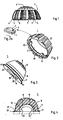
Figur 1 ein Ausführungsbeispiel des erfindungsgemäßen Trägerelementes mit eingesetztem Pfannenteil in Seitenansicht,Figur 2 das in Figure 1 dargestellte Trägerelement in perspektivischer Darstellung schräg von unten gesehen,- Figur 2a eine Darstellung eines Details gemäß
Figur 2, Figur 3 ein Pfanneneinsatz für das inFigur 2 dargestellte Trägerelement, ebenfalls in perspektivischer Ansicht,- Figur 4 eine Schnittdarstellung eines in Trägerelement einsetzbaren Einsatzes,
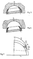
Figur 5 eine Schnittdarstellungen eines in eines Knochenexkavitation eingesetzten Trägerelements,Figur 6 eine Schnittdarstellung des Trägerelementes gemäßFigur 5 während des Einschraubvorgangs sowieFigur 7 eine Dartstellung der geometrischen Verhältnisse beiFigur 6 in vergrößerter Wiedergabe.
- 1 shows an embodiment of the support element according to the invention with inserted pan part in side view,
- FIG. 2 shows the carrier element shown in FIG. 1 in a perspective view obliquely from below,
- FIG. 2a shows an illustration of a detail according to FIG. 2,
- FIG. 3 shows a pan insert for the one in FIG. 2 shown support element, also in perspective view,
- FIG. 4 shows a sectional illustration of an insert which can be used in the carrier element,
- FIG. 5 shows a sectional illustration of a carrier element inserted into a bone excavation,
- Figure 6 is a sectional view of the carrier element according to Figure 5 during the screwing process and
- FIG. 7 shows a representation of the geometric relationships in FIG. 6 in an enlarged representation.
Bei dem in Figur 1 dargestellten Trägerelement 1, welches ringförmig ausgebildet ist und dessen Außenfläche der Oberfläche einer Kugelzone entspricht, sind eine Anzahl von geneigt angeordneten Gewindesegmenten 2 vorgesehen, welche durch Schneidnuten 3 voneinander getrennt sind. Die Gewindesegmente sind an ihren beim Einschrauben vorangeführten Teilen scharfkantig ausgeführt und stehen hier am weitesten von der Kugeloberfläche ab. Sie bilden im Bereich der Schneidnuten scharfkantige Spitzen, welche beispielhaft mit 4 bezeichnet sind. In bezogen auf die beim Einschrauben aufzuwendende Drehrichtung weiter zurückliegenden Bereichen sind die Gewindesegmente zu ihren Außenkanten abgestumpft bis abgeflacht ausgebildet, was durch eine parallele Bearbeitung der übereinanderliegenden Gewindesegmente mittels Fräsen oder dgl. erfolgen kann. Das ringförmige Trägerelement besteht bevorzugt aus Titan, dessen Elastizitätseigenschaften bei geeigneter Querschnittsbemessung in etwa denen des umgebenden Knochenmaterials entspricht.In the
Ein Pfanneneinsatz 5 ist an die inneren Querschnittsabmessungen des Trägerelementes 1 angepaßt und läßt sich in das bereits in den Knochen eingeschraubte Trägerelement von unten her einsetzen, wobei der obere kuppelförmige Bereich 6 des Einsatzes das Trägerelement überragt und sich im eingesetzten Zustand im Inneren der im Knochen angebrachten Aussparung abstützt.A
In den Figuren 2 und 3 sind Trägerelement 1 und Einsatzteil 5 für sich getrennt in perspketivischer Darstellung wiedergegeben. Die beiden Teile weisen aneinander angepaßte konisch geformte Bereiche 7 und 8 auf, welche mit einem gewissen Spiel behaftet sein können. Durch dieses Spiel kann die Elastizität des Ringes durch eine gerinfügige Verbiegung der Ringform wirksam werden. Die Krafteinleitung erfolgt über die Flanken des Kegelstumpfes 8. Der in Figur 3 wiedergegebene Einsatz 5 weist an seiner Unterseite eine Ausnehmung 16 zur Aufnahme des Kopfes der Femurschaftprothese auf. Aussparungen 17 bis 20 an einem Ansatz 21 ermöglichen zusammen mit einer Nase 22 am Trag ring 1 unterschiedliche Positionen des Einsatzes 5.In FIGS. 2 and 3,
In Figur 2a ist als Ausschnitt aus der Figur 2 ein einzelnes Gewindesegment 2 wiedergegeben. Es ist ersichtlich, daß bei Voranbewegung in Pfeilrichtung zum Einschrauben der vorangeführte höchste Bereich des Segments 2 als Schneidwerkzeug dient, während der hintere Teil einen ausreichenden Freiwinkel aufweist und auf diese Weise auch ein Festklemmen des Rings beim Einschrauben sicher verhindert. Der "Rüken" des Gewindesegments wird bevorzugt durch ein-oder mehrfaches Uberfräsen erzeugt, so daß sich entsprechend eine mehreckige oder verrundete Struktur des Gewindesgements ergibt. Der beim Einschrauben vorangeführte Bereich entrspricht dem vollständigen Gewindeprofil, während die nachgeführten Teile in ihrer maximalen Oberfläche zunehmend verringert sind.A
Die Teile 1 und 5 sind ineinander schnappbar, wobei in eine entsprechende Rille des Einsatzteiles ein Drahtring 9 eingelegt ist, der in eine entsprechende Rille 10 des Trägerelementes 1 eingreift. Aussparungen 11 und 12 an der Unterseite des Trägerelementes diene zur Aufnahme eines Einschraubwerkzeuges, wobei durch die gleichmäßige Verteilung der Aussparungen (von denen zwei nicht sichtbar sind) ein exaktes Dirigieren während des Einschraubens möglich ist. Der kuppelförmig geformte Bereich 6 des Einsatzteiles 5 weist eine Strukturierung 13 auf, die mit der Knockenoberfläche in Kontakt kommet.The
Die Einsätze stehen in unterschieldlichen Ausführungen zur Verfügung, wobei nach dem Einschrauben des Trägerteils 1 ein geeignetes Ensatzelement ausgewählt wird. Hierzu stehen geeignete Tiefenmeßelemente zur Verfügung, welche prinzipiell die Form des in Figur 3 dargestellten Einsatzes haben, wobei zusätzlich im Bereich der Kuppel eine (gestrichelt dargestellte) Aussparung 14 vorgesehen sein kann, welche beim Blick von unten durch den eingeschraubten Ring 1 hindurch eine Beurteilung zuläßt, ob der kuppelförmige Bereich 6 des Einsatzes 5 den Knochen erreicht. Die Aussparung 14 bildet damit eine Art "Fenster". Bei dem speziellen dieses Fenster aufweisenden Meßeinsatz-enfällt der Ring 9, wobei stattdessen bevorzugt auf dem zylindrischen Bereich Markierungen vorgesehen sind, welche in bezug auf die Kante zwischen zylindrischem und kegeligem Bereich des Einsatzes 1 angeben, welcher von mehreren Einsätzen im betreffenden Fall jeweils den besten Sitz bietet.The inserts are available in different versions, a suitable insert element being selected after screwing in the
Es ist ersichtlich, daß die ringförmige Gestalt des Trägerelementes 1 einerseits für einen stabilen Sitz des Prothesenelementes (ohne Verwendung von Knochenzement) in der Weise sorgt, daß die eigentliche Pfanne 5 präzise gehalten ist und nicht ihre einmal gefundene optimal justierte Position verlassen kann. Die Übertragung von bei Belastung der Prothese vorzugsweise auftretenden Druckkräfte erfolgt aber zum größten Teil über den kuppelförmigen Bereich des Einsatzes und zum anderen Teil auch über den kegeligen Ansatz, wobei mit diesem eine selbsttätige Zentrierung verbunden ist.It can be seen that the annular shape of the
Der Ring gestattet beim Einschrauben infolge seiner inneren Öffnung einen großflächigen Durchblick auf den Innenbereich der Knockenaussparung, so daß zuverlässig beurteilt werden kann, wenn das Tragelement 1 beim Einschrau ben seine Endposition erreicht hat. Gerade bei sich verjüngenden Gewinden wird die volle Tragfähgkeit erst dann erreicht, wenn das Gewinde vollständig eingeschraupt ist und sich der Träger bündig an den Knochenhohlraum anschließt.The ring allows a large view of the inner area of the knock recess when screwing in due to its inner opening, so that it can be reliably assessed when the
In der Figur 4 ist eine Ausführung eines Einsatzes mit unterschiedlichen Varianten von Aussparungen (gestrichelt) im Schnitt dargestellt, der zu dem erfindungsgemäßen System gehört, wobei alle Einsätze in ihren zylindrischen und konischen Außenbereich an den in den entsprechenden Figuren dargestellten ringförmigen Träger 1 angepaßt sind. Durch die unterschiedliche relative Lage der Ausnehmung 16 (Ausführungen 22' und 23 gestrichelt dargestellt) läßt sich jedoch der Drehpunkt für den Kopf der Schenkelhalsprothese entsprechend verlagern, so daß eine individuelle Anpassung möglich ist. Dabei ermöglicht die gestrichelt dargestellte Ausführung 22' eine unterschiedliche Höhenposition in bezug auf die Knockenoberfläche, während die gestrichelte Ausführung 23 für eine die exzentrische Aufnahme für den Prothesenkopf ausgebildet ist. Die Exentrizität kann durch Drehen des Einsatzes in eine geeignete Richtung gebracht werden, wobei die unterschiedlichen Raststellungen die jeweils eingestellte Position fixieren (Aussparungen 17 bis 20 in Figur 3 mit Nase 22 in Figur 2).FIG. 4 shows an embodiment of an insert with different variants of cutouts (dashed) in section, which belongs to the system according to the invention, with all the inserts in their cylindrical and conical outer area being adapted to the
Bei einer bevorzugten nicht dargestellten Ausführungsform sind an dem Einsatz 5 in Figur 3 Erhebungen vorgesehen, welche in die Ausparungen 11, 12 für den Steckschlüssel am Einsatz 1 in Figur 2 angepaßt sind. Auf diese Weise ist eine Drehsicherung des Einsatzes 5 auch gewährleistet, wenn die Nase 22 entfällt. Die Aussparungen 11 und 12 erhalten damit eine Doppelfunktion.In a preferred embodiment, not shown, bumps are provided on the
Es sind weitere Einsätze möglich, welche unterschiedliche Höhen- und Achsenanordnungen miteinander kombinieren, so daß den auftretenden Anforderungen unter Berücksichtigung des in seiner optimalen Position beispielsweise bei Dysplasie eingeschraubten Trägerringes in jeder Weise Rechnung getragen werden kann. Eine gewünschte Neigung der Achsenrichtung wird nicht mittels eines speziellen Ein satzes, sondern über die Einschraubrichtung des Trägerelementes festgelegt, wie es nachfolgend dargestellt ist. Zur Aufnahme einer nicht dargestellten sogenannten "Doppelkopfprothese" ist die Ausnehmung 16, 22' oder 23 auf eine Kugel von der Größe der Femurkopf-Gelenkkugel aufschnappbar ausgebildet. Eine derartige "Doppelkopfprothese" bildet eine vollständige Hüftgelenkprothese, bei der die Außenabmessungen der Gelenkschale derjenigen der gesunden Gelenkkugel entsprechen.Further uses are possible which combine different height and axis arrangements with one another, so that the occurring requirements can be taken into account in any way, taking into account the support ring screwed in its optimal position, for example in the case of dysplasia. A desired inclination of the axis direction is not determined by means of a special set, but rather via the screwing-in direction of the support element, as shown below. To accommodate a so-called "double head prosthesis", not shown, the
In den Figuren 5 und 6 ist bei den dortigen Schnittdarstellungen die Möglichkeit eines geneigten Einschraubens in eine Knochenexkavation 15 wiedergegeben. Es ist ersichtlich, daß bei dem selbstschneidenden Charakter des Gewindes in Verbindung mit der Oberfläche, die einen Teil einer Kugel bildet, verschiedene Positionen im halbkugelförmig ausgefrästen Knochenhohlraum erreicht werden können. Damit läßt sich das Tragelement entsprechend der Belastbarkeit des Knochens und der gewünschten Ausrichtung der Prothese einbringen. Die äußere Oberfläche des Kreisringes entspricht dabei der Oberfläche einer Kugelzone.FIGS. 5 and 6 show the possibility of an inclined screwing into a
In Figur 6 ist schematisch dargestellt, wie das Einschneiden der Gewindesegmente des Trägeelementes in die Aussparung erfolgt.FIG. 6 shows schematically how the thread segments of the support element are cut into the recess.
Da der Radius der gefrästen Aussparung kleiner als der Radius der die Außenkanten der Gewindesegmente tangierenden Halbkugel und die Tangenten an die betreffenden Radien im Berührungspunkt nicht wie bei zylindrischen oder üblichen konischen Gewinden parallel verlaufen, sonderen einen spitzen Winkel miteinander bilden und sich die beiden Kugelflächen in Richtung auf den Knochen noch zunehmend von einander entfernen, ist, da die Gewindesegmente eine gewisse Steigung aufweisen und der vorangeführte Teil sich in einem Bereich befindet, wo die beiden Kugelflächen ein ander nicht berühren, ohne die hier dargestellten Maßnahmen nicht sicherstellt, daß das Gewindesegment im Bereich der Schneidnut in die Knochenoberfläche eingreift. Die Gewindesegmente würden vielmehr mit ihrem Rücken zunächst mit der knochenoberfläche in Kontakt kommen und das Selbsteinschneiden des einzuschraubenden Ringes verhinderen. Erst die entsprechende Abflachung der in Einschraubrichtung zurückliegenden Bereiche der Gewindesegmente schafft die notwendige Überhöhung des vorangeführten Teils, so daß die Schneidkanten bevorzugt punktförmig eingreifen können und somit auch den bei jedem Schneidwerkzeug notwendigen Freiwinkel aufweisen.Since the radius of the milled recess is smaller than the radius of the hemisphere tangent to the outer edges of the thread segments and the tangents to the relevant radii at the point of contact do not run parallel as with cylindrical or conventional conical threads, they form an acute angle with each other and the two spherical surfaces face each other on the bones increasingly remove from each other, because the threaded segments have a certain slope and the leading part is in an area where the two spherical surfaces do not touch one another, without the measures shown here does not ensure that the threaded segment in the area the cutting groove engages in the bone surface. Rather, the thread segments would initially come into contact with the back of the bone surface and prevent the ring to be screwed into itself. Only the corresponding flattening of the areas of the thread segments lying in the screwing-in direction creates the necessary elevation of the preceding part, so that the cutting edges can preferably engage at points and thus also have the clearance angle necessary for each cutting tool.
In Figur 7 sind in einer vergrößerten geometrischen Darstellung die Verhältnisse bei Einschraubengemäß Figur 6 wiedergegeben, wobei die beiden Dreiecke 24 und 25 auf dem inneren Umfang die Vorder- und Hinterkante eines Gewindesegments darstellen, dessen Rücken nicht, wie in Figur 2a dargestellt, angefast bzw. verrundet ist. Wegen der Steigung des Gewindesegments befinden sich die Schnittflächen gemäß Figur in unterschiedlicher Höhe, wobei das obere (gestrichelt dargestellte) Dreieck 24 die beim Einschrauben vorangeführte Kante symbolisiert. Bei einer Höhendifferenz a infolge der Steigung befindet sich die vorangeführte (Schneid-) Kante um den Betrag b von der halbkugel förmigen Exkavation 15 entfernt, während die rückwärtige Fläche (unteres Dreieck 25) anliegt. Damit liegt das Gewindesegment mit seinem Rücken an der Knochenwandung an, ohne wie ein Schneidwerkzeug eindringen zu können. Die Folge ist, daß das Trägerelement nicht in die Knochenwandung zum Erzeugen des Gewindes einschneidet sondern dort abrutscht oder klemmt. Est ist damit ersichtlich, wie die vorgenommenen Anfasungen das Einschrauben ohne vorheriges Gewindeschneiden erleichtern insbesondere wenn dieses Einschrauben in eine halbkugelige Aussparung mit geneigter Achse erfolgen soll, wie es in Figur 6 wiedergegeben ist.In FIG. 7, the conditions for screwing in according to FIG. 6 are shown in an enlarged geometric representation, the two
Claims (10)
Priority Applications (1)
| Application Number | Priority Date | Filing Date | Title |
|---|---|---|---|
| AT82730068T ATE17823T1 (en) | 1981-05-18 | 1982-05-18 | ARTIFICIAL HIP POINT. |
Applications Claiming Priority (7)
| Application Number | Priority Date | Filing Date | Title |
|---|---|---|---|
| DE3120148 | 1981-05-18 | ||
| DE3120148 | 1981-05-18 | ||
| DE3147707 | 1981-11-27 | ||
| DE19813147707 DE3147707A1 (en) | 1981-05-18 | 1981-11-27 | Part of a hip prosthesis |
| EP82730035 | 1982-03-15 | ||
| EP82730035 | 1982-03-15 | ||
| US06/487,185 US4795470A (en) | 1981-05-18 | 1983-04-21 | Two-part socket for hip-joint prosthesis |
Publications (4)
| Publication Number | Publication Date |
|---|---|
| EP0065482A2 EP0065482A2 (en) | 1982-11-24 |
| EP0065482A3 EP0065482A3 (en) | 1983-01-05 |
| EP0065482B1 EP0065482B1 (en) | 1986-02-05 |
| EP0065482B2 true EP0065482B2 (en) | 1990-10-24 |
Family
ID=27432674
Family Applications (1)
| Application Number | Title | Priority Date | Filing Date |
|---|---|---|---|
| EP82730068A Expired - Lifetime EP0065482B2 (en) | 1981-05-18 | 1982-05-18 | Artificial hip socket |
Country Status (4)
| Country | Link |
|---|---|
| US (1) | US4795470A (en) |
| EP (1) | EP0065482B2 (en) |
| AT (1) | ATE17823T1 (en) |
| DE (2) | DE3147707A1 (en) |
Families Citing this family (66)
| Publication number | Priority date | Publication date | Assignee | Title |
|---|---|---|---|---|
| US4623352A (en) * | 1982-01-18 | 1986-11-18 | Indong Oh | Protrusio cup |
| IE53930B1 (en) * | 1982-04-07 | 1989-04-12 | Nat Res Dev | Endoprosthetic bone joint devices |
| US4978356A (en) * | 1983-03-08 | 1990-12-18 | Joint Medical Products Corporation | Ball and socket bearing for artificial joint |
| US4678472A (en) | 1983-03-08 | 1987-07-07 | Joint Medical Products Corporation | Ball and socket bearing for artificial joint |
| US6042611A (en) * | 1983-03-08 | 2000-03-28 | Joint Medical Products Corporation | Ball and socket bearing for artificial joint |
| US4801301A (en) * | 1983-03-08 | 1989-01-31 | Joint Medical Products Corporation | Ball and socket bearing for artificial joint |
| US4960427A (en) * | 1983-03-08 | 1990-10-02 | Joint Medical Products Corporation | Ball and socket bearing for artifical joint |
| FR2554342A1 (en) * | 1983-11-09 | 1985-05-10 | Sorem | Improvements made to self-sustaining cotyloid prostheses |
| EP0142759A3 (en) * | 1983-11-22 | 1985-12-27 | Protek AG | Hip joint cup |
| CH663894A5 (en) * | 1984-07-16 | 1988-01-29 | Sulzer Ag | ENDOPROTHESIS OF AN INNER PANEL AND AN OUTER SHELL FOR A HIP JOINT PAN. |
| DE8431422U1 (en) * | 1984-10-23 | 1985-11-21 | Mecron Medizinische Produkte Gmbh, 1000 Berlin | Support element |
| DE8500869U1 (en) * | 1985-01-11 | 1985-12-19 | Mecron Medizinische Produkte Gmbh, 1000 Berlin | Artificial hip socket with a support element and a socket insert |
| FR2590478A1 (en) * | 1985-11-26 | 1987-05-29 | Lahille Michel | Artificial acetabulum |
| FR2591471A1 (en) * | 1985-12-18 | 1987-06-19 | Bernard Caignan | Improvement to hip prostheses of the screwed acetabular ring type |
| FR2592787B1 (en) * | 1986-01-10 | 1991-07-12 | Jean Lagrange | RETAINING INSERT SCREW RING |
| CA1290099C (en) * | 1986-01-21 | 1991-10-08 | Thomas H. Mallory | Porous-coated artificial joints |
| US4695282A (en) * | 1986-01-23 | 1987-09-22 | Osteonics Corp. | Acetabular cup assembly with selective bearing face orientation |
| CH668901A5 (en) * | 1986-02-18 | 1989-02-15 | Sulzer Ag | ENDOPROSTHETATION FOR A HIP ACTION. |
| FR2597329B1 (en) * | 1986-04-18 | 1988-08-05 | Cuilleron J | ILIAC BONE COTYL REHABILITATION ASSEMBLY FOR RECEIVING A FEMALE HEAD. |
| FR2598609B1 (en) * | 1986-05-16 | 1988-10-21 | Courtois Serge | HIP PROSTHESIS |
| DE3620460C1 (en) * | 1986-06-18 | 1987-10-08 | Buse Harry | Socket for an endoprosthesis, especially for hip endoprostheses |
| CH670949A5 (en) * | 1986-09-23 | 1989-07-31 | Sulzer Ag | |
| IT1202437B (en) * | 1987-01-28 | 1989-02-09 | Cremascoli Spa G | STRUCTURE OF TOTAL ANCHOR PROSTHESIS, INCLUDING A FEMORAL COMPONENT AND AN ACETABULAR COMPONENT, REALIZED, BOTH, PART IN METAL MATERIAL AND PART IN CERAMIC MATERIAL |
| CH671687A5 (en) * | 1987-03-30 | 1989-09-29 | Sulzer Ag | |
| DE3804310C1 (en) * | 1988-02-09 | 1989-07-06 | Mecron Medizinische Produkte Gmbh, 1000 Berlin, De | |
| DE8810783U1 (en) * | 1988-06-06 | 1988-10-20 | Mecron Medizinische Produkte Gmbh, 1000 Berlin, De | |
| US5217499A (en) * | 1988-08-17 | 1993-06-08 | Minnesota Mining And Manufacturing Company | Rim-bearing acetabular component of hip joint prosthesis |
| GB8819588D0 (en) * | 1988-08-17 | 1988-09-21 | Minnesota Mining & Mfg | Screw-threaded acetabular component of hip joint prosthesis |
| CH675823A5 (en) * | 1988-08-24 | 1990-11-15 | Sulzer Ag | |
| US4976730A (en) * | 1988-10-11 | 1990-12-11 | Kwan Gett Clifford S | Artificial pericardium |
| US4892549B1 (en) * | 1989-01-31 | 1999-10-05 | Stryker Corp | Dual-radius acetubular cup component |
| US5314491A (en) * | 1990-02-02 | 1994-05-24 | Zimmer, Inc. | Prosthetic socket implant |
| US5049158A (en) * | 1990-04-20 | 1991-09-17 | Boehringer Mannheim Corporation | Acetabular cup assembly |
| DE9014542U1 (en) * | 1990-10-20 | 1991-01-03 | Howmedica Gmbh, 2314 Schoenkirchen, De | |
| US5443519A (en) * | 1993-04-22 | 1995-08-22 | Implex Corporation | Prosthetic ellipsoidal acetabular cup |
| US5549701A (en) * | 1993-09-20 | 1996-08-27 | Mikhail; W. E. Michael | Acetabular cup |
| US5480448A (en) * | 1993-09-20 | 1996-01-02 | Mikhail; W. E. Michael | Acetabular cup groove insert |
| US20020143402A1 (en) * | 1995-09-04 | 2002-10-03 | Limber Ltd. | Hip joint prostheses |
| US5782928A (en) * | 1995-11-27 | 1998-07-21 | Smith & Nephew, Inc. | Acetabular cup body prosthesis |
| US5676704A (en) * | 1995-11-27 | 1997-10-14 | Smith & Nephew, Inc. | Acetabular cup body prosthesis |
| US5639280A (en) * | 1996-02-02 | 1997-06-17 | Zimmer, Inc. | Constraining ring for a hip cup |
| AU729561B2 (en) * | 1996-10-23 | 2001-02-01 | Smith & Nephew, Inc. | Acetabular cup body prosthesis |
| US7255712B1 (en) | 1997-04-15 | 2007-08-14 | Active Implants Corporation | Bone growth promoting implant |
| US6132469A (en) * | 1997-11-07 | 2000-10-17 | Biomet, Inc. | Acetabular liner extractor |
| US6139582A (en) * | 1997-11-21 | 2000-10-31 | Depuy Orthopaedics, Inc. | Acetabular cup with bi-directional steps |
| AU783205C (en) * | 2000-03-15 | 2006-08-17 | Depuy Orthopaedics, Inc. | Prosthetic cup assembly which includes components possessing self-locking taper |
| US20020120340A1 (en) | 2001-02-23 | 2002-08-29 | Metzger Robert G. | Knee joint prosthesis |
| US7497874B1 (en) | 2001-02-23 | 2009-03-03 | Biomet Manufacturing Corp. | Knee joint prosthesis |
| US7326253B2 (en) * | 2001-11-16 | 2008-02-05 | Depuy Products, Inc. | Prosthetic cup assembly having increased assembly congruency |
| DE60235400D1 (en) * | 2001-12-04 | 2010-04-01 | Active Implants Corp | CUSHIONING IMPLANTS FOR LOAD-WEARING APPLICATIONS |
| WO2003099156A2 (en) * | 2002-05-23 | 2003-12-04 | Discure, Ltd. | Joint and dental implants |
| US20060226570A1 (en) | 2005-04-12 | 2006-10-12 | Zimmer Technology, Inc. | Method for making a metal-backed acetabular implant |
| WO2007084939A2 (en) | 2006-01-20 | 2007-07-26 | Zimmer Technology, Inc. | Shoulder arthroplasty system |
| WO2007108848A1 (en) | 2006-03-20 | 2007-09-27 | Smith & Nephew, Inc. | Acetabular cup assembly for multiple bearing materials |
| US8187280B2 (en) | 2007-10-10 | 2012-05-29 | Biomet Manufacturing Corp. | Knee joint prosthesis system and method for implantation |
| US8328873B2 (en) | 2007-01-10 | 2012-12-11 | Biomet Manufacturing Corp. | Knee joint prosthesis system and method for implantation |
| US8562616B2 (en) * | 2007-10-10 | 2013-10-22 | Biomet Manufacturing, Llc | Knee joint prosthesis system and method for implantation |
| US8163028B2 (en) * | 2007-01-10 | 2012-04-24 | Biomet Manufacturing Corp. | Knee joint prosthesis system and method for implantation |
| JP5448842B2 (en) | 2007-01-10 | 2014-03-19 | バイオメト マニファクチャリング コーポレイション | Knee joint prosthesis system and implantation method |
| US8211184B2 (en) * | 2009-04-20 | 2012-07-03 | Michael D. Ries | Acetabular cup |
| US9023112B2 (en) | 2011-02-24 | 2015-05-05 | Depuy (Ireland) | Maintaining proper mechanics THA |
| US9668745B2 (en) | 2011-12-19 | 2017-06-06 | Depuy Ireland Unlimited Company | Anatomical concentric spheres THA |
| US8858645B2 (en) | 2012-06-21 | 2014-10-14 | DePuy Synthes Products, LLC | Constrained mobile bearing hip assembly |
| CN108836576A (en) * | 2018-07-18 | 2018-11-20 | 北京爱康宜诚医疗器材有限公司 | replacement prosthesis |
| EP3685805B1 (en) | 2019-01-25 | 2021-10-06 | Howmedica Osteonics Corp. | Cemented acetabular construct with locked modular sleeve |
| US20200261232A1 (en) * | 2019-02-15 | 2020-08-20 | Howmedica Osteonics Corp. | Robotic Acetabulum Preparation For Acceptance of Acetabular Cup With Engagement Features |
Family Cites Families (15)
| Publication number | Priority date | Publication date | Assignee | Title |
|---|---|---|---|---|
| FR1287526A (en) * | 1961-01-23 | 1962-03-16 | Coxofemoral joint replacement prosthesis | |
| US3820167A (en) * | 1968-06-18 | 1974-06-28 | K Sivash | Artificial hip joint |
| DE2129832A1 (en) * | 1970-06-19 | 1971-12-30 | Harris William H | Hip joint prosthesis and process for its manufacture |
| DE2314708C3 (en) * | 1973-03-24 | 1980-04-10 | Joachim Prof. Dr.Med. 6200 Wiesbaden Eichler | Joint socket for an artificial hip joint |
| US3840904A (en) * | 1973-04-30 | 1974-10-15 | R Tronzo | Acetabular cup prosthesis |
| US3818512A (en) * | 1973-05-08 | 1974-06-25 | Y Shersher | Artificial hip-joint with detachable insert |
| FR2295729A1 (en) * | 1974-12-27 | 1976-07-23 | Mahay Et Cie | TOTAL HIP PROSTHESIS |
| DE2611985C3 (en) * | 1976-03-20 | 1981-08-13 | Baumann, Friedrich, Prof. Dr.Med., 8858 Neuburg | Femoral head endoprosthesis |
| DE2625529A1 (en) * | 1976-06-05 | 1977-12-15 | Sigri Elektrographit Gmbh | Prosthesis made of carbon reinforced with carbon fibres - and coated with glass ceramic forming cpds. with human bone tissue |
| DE2645101A1 (en) * | 1976-10-04 | 1978-04-06 | Staatliche Porzellan Manufaktu | Hip prosthesis with cup-shaped ball socket - with self-tapping thread interrupted by upwards tapering free grooves |
| BG27580A1 (en) * | 1978-03-17 | 1979-12-12 | Gerchev | Two- poled pelvis- thight articulation- set |
| DE2911754A1 (en) * | 1979-03-26 | 1980-10-09 | Hans Dr Reimer | Artificial hip joint socket - has peripheral ribs decreasing in dia. towards zenith and hammered into bone |
| DE2950536A1 (en) * | 1979-12-15 | 1981-07-02 | Howmedica International, Inc. Zweigniederlassung Kiel, 2300 Kiel | Artificial acetabulum - with outer shell of ceramics and inner shell of polyethylene |
| CH642840A5 (en) * | 1980-02-08 | 1984-05-15 | Allo Pro Ag | SURGICAL IMPLANT, IN PARTICULAR HIP JOINT. |
| US4437193A (en) * | 1982-01-18 | 1984-03-20 | Indong Oh | Protrusio cup |
-
1981
- 1981-11-27 DE DE19813147707 patent/DE3147707A1/en not_active Ceased
-
1982
- 1982-05-18 DE DE8282730068T patent/DE3268929D1/en not_active Expired
- 1982-05-18 EP EP82730068A patent/EP0065482B2/en not_active Expired - Lifetime
- 1982-05-18 AT AT82730068T patent/ATE17823T1/en not_active IP Right Cessation
-
1983
- 1983-04-21 US US06/487,185 patent/US4795470A/en not_active Expired - Lifetime
Also Published As
| Publication number | Publication date |
|---|---|
| ATE17823T1 (en) | 1986-02-15 |
| EP0065482B1 (en) | 1986-02-05 |
| DE3268929D1 (en) | 1986-03-20 |
| EP0065482A3 (en) | 1983-01-05 |
| DE3147707A1 (en) | 1982-12-23 |
| EP0065482A2 (en) | 1982-11-24 |
| US4795470A (en) | 1989-01-03 |
Similar Documents
| Publication | Publication Date | Title |
|---|---|---|
| EP0065482B2 (en) | Artificial hip socket | |
| EP0591594B1 (en) | Acetabular cup supporting ring | |
| EP0222159B1 (en) | Acetabula for a hip joint endoprosthesis | |
| EP0329019B1 (en) | Acetabular cup for a joint prosthesis | |
| DE102005042766B4 (en) | Plate hole of a bone plate for osteosynthesis | |
| EP1715815B1 (en) | Prosthesis for replacing the surface in the area of the ball of ball-and-socket joints | |
| EP2688517B1 (en) | Ball-and-socket implant | |
| DE60013469T2 (en) | HIKING AND SET OF HIPS | |
| EP0482320A1 (en) | Acetubular cup for receiving a joint endoprosthesis | |
| EP0666068A1 (en) | Outer shell a hip joint prosthesis acetabular cup having at least two shells and hip joint prosthesis with such an outer shell | |
| DE2950536A1 (en) | Artificial acetabulum - with outer shell of ceramics and inner shell of polyethylene | |
| EP0150198B1 (en) | Endoprosthesis for cotyloid cavity | |
| DE8500869U1 (en) | Artificial hip socket with a support element and a socket insert | |
| CH662267A5 (en) | Artificial socket. | |
| DE3901885A1 (en) | PAN FOR A JOINT OPROTHESIS | |
| EP0318679B2 (en) | Endoprosthesis for an acetabular cup | |
| DE10106863C2 (en) | Implantable cup for hip joint endoprostheses | |
| EP1411869B1 (en) | Artificial joint prosthesis | |
| DE19714050C2 (en) | Hip cup with anchoring peg | |
| WO2007082807A2 (en) | Polyaxially alignable stabilising element for endoprostheses | |
| CH677072A5 (en) | Spherical joint for hip joint prosthesis - includes cup shaped half with tapered metal shell carrying cutting thread formed by saw teeth | |
| EP1503705B1 (en) | Endoprosthesis for replacing a joint, especially a shoulder joint | |
| EP0617931A2 (en) | Artificial hip acetabular cup | |
| EP0667134B1 (en) | Orthopaedic bone implant | |
| DE102011055106B3 (en) | Hip prosthesis for total hip replacement applications during e.g. orthopedics, has shank with anchorage element transferred from inactive position into active position, where element is formed as cam rotatably supported in recess of shank |
Legal Events
| Date | Code | Title | Description |
|---|---|---|---|
| PUAI | Public reference made under article 153(3) epc to a published international application that has entered the european phase |
Free format text: ORIGINAL CODE: 0009012 |
|
| PUAL | Search report despatched |
Free format text: ORIGINAL CODE: 0009013 |
|
| AK | Designated contracting states |
Designated state(s): AT BE CH DE FR GB IT LI NL SE |
|
| AK | Designated contracting states |
Designated state(s): AT BE CH DE FR GB IT LI NL SE |
|
| 17P | Request for examination filed |
Effective date: 19830628 |
|
| ITF | It: translation for a ep patent filed |
Owner name: BARZANO' E ZANARDO MILANO S.P.A. |
|
| GRAA | (expected) grant |
Free format text: ORIGINAL CODE: 0009210 |
|
| AK | Designated contracting states |
Designated state(s): AT BE CH DE FR GB IT LI NL SE |
|
| REF | Corresponds to: |
Ref document number: 17823 Country of ref document: AT Date of ref document: 19860215 Kind code of ref document: T |
|
| ET | Fr: translation filed | ||
| REF | Corresponds to: |
Ref document number: 3268929 Country of ref document: DE Date of ref document: 19860320 |
|
| PLBI | Opposition filed |
Free format text: ORIGINAL CODE: 0009260 |
|
| 26 | Opposition filed |
Opponent name: IMPLANT MEDIZINTECHNIK GMBH & CO. BETRIEBS KG Effective date: 19861105 Opponent name: AESCULAP-WERKE AG VORMALS JETTER & SCHEERER Effective date: 19861105 |
|
| NLR1 | Nl: opposition has been filed with the epo |
Opponent name: IMPLANT MEDIZINTECHNIK GMBH & CO. BETRIEBS KG Opponent name: AESCULAP-WERKE AG VORMALS JETTER & SCHEERER |
|
| PUAH | Patent maintained in amended form |
Free format text: ORIGINAL CODE: 0009272 |
|
| STAA | Information on the status of an ep patent application or granted ep patent |
Free format text: STATUS: PATENT MAINTAINED AS AMENDED |
|
| ITF | It: translation for a ep patent filed |
Owner name: BARZANO' E ZANARDO MILANO S.P.A. |
|
| 27A | Patent maintained in amended form |
Effective date: 19901024 |
|
| AK | Designated contracting states |
Kind code of ref document: B2 Designated state(s): AT BE CH DE FR GB IT LI NL SE |
|
| ET3 | Fr: translation filed ** decision concerning opposition | ||
| NLR2 | Nl: decision of opposition | ||
| NLR3 | Nl: receipt of modified translations in the netherlands language after an opposition procedure | ||
| ITTA | It: last paid annual fee | ||
| ITPR | It: changes in ownership of a european patent |
Owner name: CAMBIO SEDE;MECRON MEDIZINISCHE PRODUKTE GMBH |
|
| REG | Reference to a national code |
Ref country code: CH Ref legal event code: PFA Free format text: JOHNSON & JOHNSON PROFESSIONAL PRODUCTS GMBH |
|
| REG | Reference to a national code |
Ref country code: FR Ref legal event code: CD Ref country code: FR Ref legal event code: CA |
|
| NLT1 | Nl: modifications of names registered in virtue of documents presented to the patent office pursuant to art. 16 a, paragraph 1 |
Owner name: JOHNSON & JOHNSON PROFESSIONAL PRODUCTS GMBH TE NO |
|
| EAL | Se: european patent in force in sweden |
Ref document number: 82730068.2 |
|
| REG | Reference to a national code |
Ref country code: CH Ref legal event code: PUE Owner name: JOHNSON & JOHNSON PROFESSIONAL PRODUCTS GMBH -DANN |
|
| NLS | Nl: assignments of ep-patents |
Owner name: JOHNSON & JOHNSON MEDICAL GMBH;JOHNSON & JOHNSON G |
|
| BECA | Be: change of holder's address |
Free format text: 960917 *JOHNSON & JOHNSON MEDICAL G.M.H.B.:OSTSTR. 1, D-22844 NORDERSTEDT |
|
| BECH | Be: change of holder |
Free format text: 960917 *JOHNSON & JOHNSON MEDICAL G.M.H.B.:OSTSTR. 1, D-22844 NORDERSTEDT |
|
| REG | Reference to a national code |
Ref country code: GB Ref legal event code: 732E |
|
| PGFP | Annual fee paid to national office [announced via postgrant information from national office to epo] |
Ref country code: DE Payment date: 19970523 Year of fee payment: 16 |
|
| PG25 | Lapsed in a contracting state [announced via postgrant information from national office to epo] |
Ref country code: DE Free format text: THE PATENT HAS BEEN ANNULLED BY A DECISION OF A NATIONAL AUTHORITY Effective date: 19980513 |
|
| PGFP | Annual fee paid to national office [announced via postgrant information from national office to epo] |
Ref country code: SE Payment date: 20010417 Year of fee payment: 20 |
|
| PGFP | Annual fee paid to national office [announced via postgrant information from national office to epo] |
Ref country code: CH Payment date: 20010511 Year of fee payment: 20 |
|
| PGFP | Annual fee paid to national office [announced via postgrant information from national office to epo] |
Ref country code: AT Payment date: 20010514 Year of fee payment: 20 |
|
| PGFP | Annual fee paid to national office [announced via postgrant information from national office to epo] |
Ref country code: GB Payment date: 20010516 Year of fee payment: 20 |
|
| PGFP | Annual fee paid to national office [announced via postgrant information from national office to epo] |
Ref country code: FR Payment date: 20010518 Year of fee payment: 20 |
|
| PGFP | Annual fee paid to national office [announced via postgrant information from national office to epo] |
Ref country code: NL Payment date: 20010531 Year of fee payment: 20 |
|
| PGFP | Annual fee paid to national office [announced via postgrant information from national office to epo] |
Ref country code: BE Payment date: 20010717 Year of fee payment: 20 |
|
| BE20 | Be: patent expired |
Free format text: 20020518 *JOHNSON & JOHNSON MEDICAL G.M.H.B. |
|
| REG | Reference to a national code |
Ref country code: GB Ref legal event code: IF02 |
|
| PG25 | Lapsed in a contracting state [announced via postgrant information from national office to epo] |
Ref country code: LI Free format text: LAPSE BECAUSE OF EXPIRATION OF PROTECTION Effective date: 20020517 Ref country code: GB Free format text: LAPSE BECAUSE OF EXPIRATION OF PROTECTION Effective date: 20020517 Ref country code: CH Free format text: LAPSE BECAUSE OF EXPIRATION OF PROTECTION Effective date: 20020517 |
|
| PG25 | Lapsed in a contracting state [announced via postgrant information from national office to epo] |
Ref country code: NL Free format text: LAPSE BECAUSE OF EXPIRATION OF PROTECTION Effective date: 20020518 Ref country code: AT Free format text: LAPSE BECAUSE OF EXPIRATION OF PROTECTION Effective date: 20020518 |
|
| REG | Reference to a national code |
Ref country code: GB Ref legal event code: PE20 Effective date: 20020517 |
|
| REG | Reference to a national code |
Ref country code: CH Ref legal event code: PL |
|
| NLV7 | Nl: ceased due to reaching the maximum lifetime of a patent |
Effective date: 20020518 |
|
| EUG | Se: european patent has lapsed |
Ref document number: 82730068.2 |
|
| APAH | Appeal reference modified |
Free format text: ORIGINAL CODE: EPIDOSCREFNO |