EP0482320A1 - Acetubular cup for receiving a joint endoprosthesis - Google Patents
Acetubular cup for receiving a joint endoprosthesis Download PDFInfo
- Publication number
- EP0482320A1 EP0482320A1 EP91114637A EP91114637A EP0482320A1 EP 0482320 A1 EP0482320 A1 EP 0482320A1 EP 91114637 A EP91114637 A EP 91114637A EP 91114637 A EP91114637 A EP 91114637A EP 0482320 A1 EP0482320 A1 EP 0482320A1
- Authority
- EP
- European Patent Office
- Prior art keywords
- shell
- outer shell
- element according
- inlay
- shell element
- Prior art date
- Legal status (The legal status is an assumption and is not a legal conclusion. Google has not performed a legal analysis and makes no representation as to the accuracy of the status listed.)
- Granted
Links
- 210000001981 hip bone Anatomy 0.000 claims abstract description 23
- 210000000988 bone and bone Anatomy 0.000 claims abstract description 21
- 239000000126 substance Substances 0.000 claims abstract description 10
- 238000002513 implantation Methods 0.000 claims abstract description 7
- 210000004394 hip joint Anatomy 0.000 claims abstract description 4
- 238000003466 welding Methods 0.000 claims description 2
- 239000002131 composite material Substances 0.000 claims 1
- 238000010348 incorporation Methods 0.000 abstract 1
- 210000000588 acetabulum Anatomy 0.000 description 1
- 238000004873 anchoring Methods 0.000 description 1
- 230000000694 effects Effects 0.000 description 1
- 230000007774 longterm Effects 0.000 description 1
- 238000010079 rubber tapping Methods 0.000 description 1
Images
Classifications
-
- A—HUMAN NECESSITIES
- A61—MEDICAL OR VETERINARY SCIENCE; HYGIENE
- A61F—FILTERS IMPLANTABLE INTO BLOOD VESSELS; PROSTHESES; DEVICES PROVIDING PATENCY TO, OR PREVENTING COLLAPSING OF, TUBULAR STRUCTURES OF THE BODY, e.g. STENTS; ORTHOPAEDIC, NURSING OR CONTRACEPTIVE DEVICES; FOMENTATION; TREATMENT OR PROTECTION OF EYES OR EARS; BANDAGES, DRESSINGS OR ABSORBENT PADS; FIRST-AID KITS
- A61F2/00—Filters implantable into blood vessels; Prostheses, i.e. artificial substitutes or replacements for parts of the body; Appliances for connecting them with the body; Devices providing patency to, or preventing collapsing of, tubular structures of the body, e.g. stents
- A61F2/02—Prostheses implantable into the body
- A61F2/30—Joints
- A61F2/32—Joints for the hip
- A61F2/34—Acetabular cups
-
- A—HUMAN NECESSITIES
- A61—MEDICAL OR VETERINARY SCIENCE; HYGIENE
- A61F—FILTERS IMPLANTABLE INTO BLOOD VESSELS; PROSTHESES; DEVICES PROVIDING PATENCY TO, OR PREVENTING COLLAPSING OF, TUBULAR STRUCTURES OF THE BODY, e.g. STENTS; ORTHOPAEDIC, NURSING OR CONTRACEPTIVE DEVICES; FOMENTATION; TREATMENT OR PROTECTION OF EYES OR EARS; BANDAGES, DRESSINGS OR ABSORBENT PADS; FIRST-AID KITS
- A61F2/00—Filters implantable into blood vessels; Prostheses, i.e. artificial substitutes or replacements for parts of the body; Appliances for connecting them with the body; Devices providing patency to, or preventing collapsing of, tubular structures of the body, e.g. stents
- A61F2/02—Prostheses implantable into the body
- A61F2/28—Bones
- A61F2002/2835—Bone graft implants for filling a bony defect or an endoprosthesis cavity, e.g. by synthetic material or biological material
-
- A—HUMAN NECESSITIES
- A61—MEDICAL OR VETERINARY SCIENCE; HYGIENE
- A61F—FILTERS IMPLANTABLE INTO BLOOD VESSELS; PROSTHESES; DEVICES PROVIDING PATENCY TO, OR PREVENTING COLLAPSING OF, TUBULAR STRUCTURES OF THE BODY, e.g. STENTS; ORTHOPAEDIC, NURSING OR CONTRACEPTIVE DEVICES; FOMENTATION; TREATMENT OR PROTECTION OF EYES OR EARS; BANDAGES, DRESSINGS OR ABSORBENT PADS; FIRST-AID KITS
- A61F2/00—Filters implantable into blood vessels; Prostheses, i.e. artificial substitutes or replacements for parts of the body; Appliances for connecting them with the body; Devices providing patency to, or preventing collapsing of, tubular structures of the body, e.g. stents
- A61F2/02—Prostheses implantable into the body
- A61F2/30—Joints
- A61F2002/30001—Additional features of subject-matter classified in A61F2/28, A61F2/30 and subgroups thereof
- A61F2002/30316—The prosthesis having different structural features at different locations within the same prosthesis; Connections between prosthetic parts; Special structural features of bone or joint prostheses not otherwise provided for
- A61F2002/30317—The prosthesis having different structural features at different locations within the same prosthesis
- A61F2002/30324—The prosthesis having different structural features at different locations within the same prosthesis differing in thickness
-
- A—HUMAN NECESSITIES
- A61—MEDICAL OR VETERINARY SCIENCE; HYGIENE
- A61F—FILTERS IMPLANTABLE INTO BLOOD VESSELS; PROSTHESES; DEVICES PROVIDING PATENCY TO, OR PREVENTING COLLAPSING OF, TUBULAR STRUCTURES OF THE BODY, e.g. STENTS; ORTHOPAEDIC, NURSING OR CONTRACEPTIVE DEVICES; FOMENTATION; TREATMENT OR PROTECTION OF EYES OR EARS; BANDAGES, DRESSINGS OR ABSORBENT PADS; FIRST-AID KITS
- A61F2/00—Filters implantable into blood vessels; Prostheses, i.e. artificial substitutes or replacements for parts of the body; Appliances for connecting them with the body; Devices providing patency to, or preventing collapsing of, tubular structures of the body, e.g. stents
- A61F2/02—Prostheses implantable into the body
- A61F2/30—Joints
- A61F2002/30001—Additional features of subject-matter classified in A61F2/28, A61F2/30 and subgroups thereof
- A61F2002/30316—The prosthesis having different structural features at different locations within the same prosthesis; Connections between prosthetic parts; Special structural features of bone or joint prostheses not otherwise provided for
- A61F2002/30329—Connections or couplings between prosthetic parts, e.g. between modular parts; Connecting elements
- A61F2002/30331—Connections or couplings between prosthetic parts, e.g. between modular parts; Connecting elements made by longitudinally pushing a protrusion into a complementarily-shaped recess, e.g. held by friction fit
- A61F2002/30332—Conically- or frustoconically-shaped protrusion and recess
- A61F2002/30336—Stepped cones, i.e. having discrete diameter changes
-
- A—HUMAN NECESSITIES
- A61—MEDICAL OR VETERINARY SCIENCE; HYGIENE
- A61F—FILTERS IMPLANTABLE INTO BLOOD VESSELS; PROSTHESES; DEVICES PROVIDING PATENCY TO, OR PREVENTING COLLAPSING OF, TUBULAR STRUCTURES OF THE BODY, e.g. STENTS; ORTHOPAEDIC, NURSING OR CONTRACEPTIVE DEVICES; FOMENTATION; TREATMENT OR PROTECTION OF EYES OR EARS; BANDAGES, DRESSINGS OR ABSORBENT PADS; FIRST-AID KITS
- A61F2/00—Filters implantable into blood vessels; Prostheses, i.e. artificial substitutes or replacements for parts of the body; Appliances for connecting them with the body; Devices providing patency to, or preventing collapsing of, tubular structures of the body, e.g. stents
- A61F2/02—Prostheses implantable into the body
- A61F2/30—Joints
- A61F2002/30001—Additional features of subject-matter classified in A61F2/28, A61F2/30 and subgroups thereof
- A61F2002/30316—The prosthesis having different structural features at different locations within the same prosthesis; Connections between prosthetic parts; Special structural features of bone or joint prostheses not otherwise provided for
- A61F2002/30329—Connections or couplings between prosthetic parts, e.g. between modular parts; Connecting elements
- A61F2002/30331—Connections or couplings between prosthetic parts, e.g. between modular parts; Connecting elements made by longitudinally pushing a protrusion into a complementarily-shaped recess, e.g. held by friction fit
- A61F2002/30354—Cylindrically-shaped protrusion and recess, e.g. cylinder of circular basis
- A61F2002/30357—Stepped cylinders, i.e. having discrete diameter changes
-
- A—HUMAN NECESSITIES
- A61—MEDICAL OR VETERINARY SCIENCE; HYGIENE
- A61F—FILTERS IMPLANTABLE INTO BLOOD VESSELS; PROSTHESES; DEVICES PROVIDING PATENCY TO, OR PREVENTING COLLAPSING OF, TUBULAR STRUCTURES OF THE BODY, e.g. STENTS; ORTHOPAEDIC, NURSING OR CONTRACEPTIVE DEVICES; FOMENTATION; TREATMENT OR PROTECTION OF EYES OR EARS; BANDAGES, DRESSINGS OR ABSORBENT PADS; FIRST-AID KITS
- A61F2/00—Filters implantable into blood vessels; Prostheses, i.e. artificial substitutes or replacements for parts of the body; Appliances for connecting them with the body; Devices providing patency to, or preventing collapsing of, tubular structures of the body, e.g. stents
- A61F2/02—Prostheses implantable into the body
- A61F2/30—Joints
- A61F2002/30001—Additional features of subject-matter classified in A61F2/28, A61F2/30 and subgroups thereof
- A61F2002/30316—The prosthesis having different structural features at different locations within the same prosthesis; Connections between prosthetic parts; Special structural features of bone or joint prostheses not otherwise provided for
- A61F2002/30329—Connections or couplings between prosthetic parts, e.g. between modular parts; Connecting elements
- A61F2002/30476—Connections or couplings between prosthetic parts, e.g. between modular parts; Connecting elements locked by an additional locking mechanism
- A61F2002/305—Snap connection
-
- A—HUMAN NECESSITIES
- A61—MEDICAL OR VETERINARY SCIENCE; HYGIENE
- A61F—FILTERS IMPLANTABLE INTO BLOOD VESSELS; PROSTHESES; DEVICES PROVIDING PATENCY TO, OR PREVENTING COLLAPSING OF, TUBULAR STRUCTURES OF THE BODY, e.g. STENTS; ORTHOPAEDIC, NURSING OR CONTRACEPTIVE DEVICES; FOMENTATION; TREATMENT OR PROTECTION OF EYES OR EARS; BANDAGES, DRESSINGS OR ABSORBENT PADS; FIRST-AID KITS
- A61F2/00—Filters implantable into blood vessels; Prostheses, i.e. artificial substitutes or replacements for parts of the body; Appliances for connecting them with the body; Devices providing patency to, or preventing collapsing of, tubular structures of the body, e.g. stents
- A61F2/02—Prostheses implantable into the body
- A61F2/30—Joints
- A61F2002/30001—Additional features of subject-matter classified in A61F2/28, A61F2/30 and subgroups thereof
- A61F2002/30316—The prosthesis having different structural features at different locations within the same prosthesis; Connections between prosthetic parts; Special structural features of bone or joint prostheses not otherwise provided for
- A61F2002/30535—Special structural features of bone or joint prostheses not otherwise provided for
- A61F2002/30593—Special structural features of bone or joint prostheses not otherwise provided for hollow
-
- A—HUMAN NECESSITIES
- A61—MEDICAL OR VETERINARY SCIENCE; HYGIENE
- A61F—FILTERS IMPLANTABLE INTO BLOOD VESSELS; PROSTHESES; DEVICES PROVIDING PATENCY TO, OR PREVENTING COLLAPSING OF, TUBULAR STRUCTURES OF THE BODY, e.g. STENTS; ORTHOPAEDIC, NURSING OR CONTRACEPTIVE DEVICES; FOMENTATION; TREATMENT OR PROTECTION OF EYES OR EARS; BANDAGES, DRESSINGS OR ABSORBENT PADS; FIRST-AID KITS
- A61F2/00—Filters implantable into blood vessels; Prostheses, i.e. artificial substitutes or replacements for parts of the body; Appliances for connecting them with the body; Devices providing patency to, or preventing collapsing of, tubular structures of the body, e.g. stents
- A61F2/02—Prostheses implantable into the body
- A61F2/30—Joints
- A61F2/30767—Special external or bone-contacting surface, e.g. coating for improving bone ingrowth
- A61F2/30771—Special external or bone-contacting surface, e.g. coating for improving bone ingrowth applied in original prostheses, e.g. holes or grooves
- A61F2002/30772—Apertures or holes, e.g. of circular cross section
- A61F2002/30784—Plurality of holes
- A61F2002/30787—Plurality of holes inclined obliquely with respect to each other
-
- A—HUMAN NECESSITIES
- A61—MEDICAL OR VETERINARY SCIENCE; HYGIENE
- A61F—FILTERS IMPLANTABLE INTO BLOOD VESSELS; PROSTHESES; DEVICES PROVIDING PATENCY TO, OR PREVENTING COLLAPSING OF, TUBULAR STRUCTURES OF THE BODY, e.g. STENTS; ORTHOPAEDIC, NURSING OR CONTRACEPTIVE DEVICES; FOMENTATION; TREATMENT OR PROTECTION OF EYES OR EARS; BANDAGES, DRESSINGS OR ABSORBENT PADS; FIRST-AID KITS
- A61F2/00—Filters implantable into blood vessels; Prostheses, i.e. artificial substitutes or replacements for parts of the body; Appliances for connecting them with the body; Devices providing patency to, or preventing collapsing of, tubular structures of the body, e.g. stents
- A61F2/02—Prostheses implantable into the body
- A61F2/30—Joints
- A61F2/30767—Special external or bone-contacting surface, e.g. coating for improving bone ingrowth
- A61F2/30771—Special external or bone-contacting surface, e.g. coating for improving bone ingrowth applied in original prostheses, e.g. holes or grooves
- A61F2002/3085—Special external or bone-contacting surface, e.g. coating for improving bone ingrowth applied in original prostheses, e.g. holes or grooves with a threaded, e.g. self-tapping, bone-engaging surface, e.g. external surface
- A61F2002/30851—Multiple threadings
-
- A—HUMAN NECESSITIES
- A61—MEDICAL OR VETERINARY SCIENCE; HYGIENE
- A61F—FILTERS IMPLANTABLE INTO BLOOD VESSELS; PROSTHESES; DEVICES PROVIDING PATENCY TO, OR PREVENTING COLLAPSING OF, TUBULAR STRUCTURES OF THE BODY, e.g. STENTS; ORTHOPAEDIC, NURSING OR CONTRACEPTIVE DEVICES; FOMENTATION; TREATMENT OR PROTECTION OF EYES OR EARS; BANDAGES, DRESSINGS OR ABSORBENT PADS; FIRST-AID KITS
- A61F2/00—Filters implantable into blood vessels; Prostheses, i.e. artificial substitutes or replacements for parts of the body; Appliances for connecting them with the body; Devices providing patency to, or preventing collapsing of, tubular structures of the body, e.g. stents
- A61F2/02—Prostheses implantable into the body
- A61F2/30—Joints
- A61F2/30767—Special external or bone-contacting surface, e.g. coating for improving bone ingrowth
- A61F2/30771—Special external or bone-contacting surface, e.g. coating for improving bone ingrowth applied in original prostheses, e.g. holes or grooves
- A61F2002/3085—Special external or bone-contacting surface, e.g. coating for improving bone ingrowth applied in original prostheses, e.g. holes or grooves with a threaded, e.g. self-tapping, bone-engaging surface, e.g. external surface
- A61F2002/30858—Threads interrupted by grooves or sidewalls, e.g. flat sidewalls
-
- A—HUMAN NECESSITIES
- A61—MEDICAL OR VETERINARY SCIENCE; HYGIENE
- A61F—FILTERS IMPLANTABLE INTO BLOOD VESSELS; PROSTHESES; DEVICES PROVIDING PATENCY TO, OR PREVENTING COLLAPSING OF, TUBULAR STRUCTURES OF THE BODY, e.g. STENTS; ORTHOPAEDIC, NURSING OR CONTRACEPTIVE DEVICES; FOMENTATION; TREATMENT OR PROTECTION OF EYES OR EARS; BANDAGES, DRESSINGS OR ABSORBENT PADS; FIRST-AID KITS
- A61F2/00—Filters implantable into blood vessels; Prostheses, i.e. artificial substitutes or replacements for parts of the body; Appliances for connecting them with the body; Devices providing patency to, or preventing collapsing of, tubular structures of the body, e.g. stents
- A61F2/02—Prostheses implantable into the body
- A61F2/30—Joints
- A61F2/30767—Special external or bone-contacting surface, e.g. coating for improving bone ingrowth
- A61F2/30771—Special external or bone-contacting surface, e.g. coating for improving bone ingrowth applied in original prostheses, e.g. holes or grooves
- A61F2002/3085—Special external or bone-contacting surface, e.g. coating for improving bone ingrowth applied in original prostheses, e.g. holes or grooves with a threaded, e.g. self-tapping, bone-engaging surface, e.g. external surface
- A61F2002/30861—Special external or bone-contacting surface, e.g. coating for improving bone ingrowth applied in original prostheses, e.g. holes or grooves with a threaded, e.g. self-tapping, bone-engaging surface, e.g. external surface having threads of increasing or decreasing height
-
- A—HUMAN NECESSITIES
- A61—MEDICAL OR VETERINARY SCIENCE; HYGIENE
- A61F—FILTERS IMPLANTABLE INTO BLOOD VESSELS; PROSTHESES; DEVICES PROVIDING PATENCY TO, OR PREVENTING COLLAPSING OF, TUBULAR STRUCTURES OF THE BODY, e.g. STENTS; ORTHOPAEDIC, NURSING OR CONTRACEPTIVE DEVICES; FOMENTATION; TREATMENT OR PROTECTION OF EYES OR EARS; BANDAGES, DRESSINGS OR ABSORBENT PADS; FIRST-AID KITS
- A61F2/00—Filters implantable into blood vessels; Prostheses, i.e. artificial substitutes or replacements for parts of the body; Appliances for connecting them with the body; Devices providing patency to, or preventing collapsing of, tubular structures of the body, e.g. stents
- A61F2/02—Prostheses implantable into the body
- A61F2/30—Joints
- A61F2/30767—Special external or bone-contacting surface, e.g. coating for improving bone ingrowth
- A61F2/30771—Special external or bone-contacting surface, e.g. coating for improving bone ingrowth applied in original prostheses, e.g. holes or grooves
- A61F2002/3085—Special external or bone-contacting surface, e.g. coating for improving bone ingrowth applied in original prostheses, e.g. holes or grooves with a threaded, e.g. self-tapping, bone-engaging surface, e.g. external surface
- A61F2002/30873—Threadings machined on non-cylindrical external surfaces
-
- A—HUMAN NECESSITIES
- A61—MEDICAL OR VETERINARY SCIENCE; HYGIENE
- A61F—FILTERS IMPLANTABLE INTO BLOOD VESSELS; PROSTHESES; DEVICES PROVIDING PATENCY TO, OR PREVENTING COLLAPSING OF, TUBULAR STRUCTURES OF THE BODY, e.g. STENTS; ORTHOPAEDIC, NURSING OR CONTRACEPTIVE DEVICES; FOMENTATION; TREATMENT OR PROTECTION OF EYES OR EARS; BANDAGES, DRESSINGS OR ABSORBENT PADS; FIRST-AID KITS
- A61F2/00—Filters implantable into blood vessels; Prostheses, i.e. artificial substitutes or replacements for parts of the body; Appliances for connecting them with the body; Devices providing patency to, or preventing collapsing of, tubular structures of the body, e.g. stents
- A61F2/02—Prostheses implantable into the body
- A61F2/30—Joints
- A61F2/32—Joints for the hip
- A61F2/34—Acetabular cups
- A61F2002/3401—Acetabular cups with radial apertures, e.g. radial bores for receiving fixation screws
- A61F2002/3403—Polar aperture
-
- A—HUMAN NECESSITIES
- A61—MEDICAL OR VETERINARY SCIENCE; HYGIENE
- A61F—FILTERS IMPLANTABLE INTO BLOOD VESSELS; PROSTHESES; DEVICES PROVIDING PATENCY TO, OR PREVENTING COLLAPSING OF, TUBULAR STRUCTURES OF THE BODY, e.g. STENTS; ORTHOPAEDIC, NURSING OR CONTRACEPTIVE DEVICES; FOMENTATION; TREATMENT OR PROTECTION OF EYES OR EARS; BANDAGES, DRESSINGS OR ABSORBENT PADS; FIRST-AID KITS
- A61F2/00—Filters implantable into blood vessels; Prostheses, i.e. artificial substitutes or replacements for parts of the body; Appliances for connecting them with the body; Devices providing patency to, or preventing collapsing of, tubular structures of the body, e.g. stents
- A61F2/02—Prostheses implantable into the body
- A61F2/30—Joints
- A61F2/32—Joints for the hip
- A61F2/34—Acetabular cups
- A61F2002/3401—Acetabular cups with radial apertures, e.g. radial bores for receiving fixation screws
- A61F2002/3406—Oblong apertures
-
- A—HUMAN NECESSITIES
- A61—MEDICAL OR VETERINARY SCIENCE; HYGIENE
- A61F—FILTERS IMPLANTABLE INTO BLOOD VESSELS; PROSTHESES; DEVICES PROVIDING PATENCY TO, OR PREVENTING COLLAPSING OF, TUBULAR STRUCTURES OF THE BODY, e.g. STENTS; ORTHOPAEDIC, NURSING OR CONTRACEPTIVE DEVICES; FOMENTATION; TREATMENT OR PROTECTION OF EYES OR EARS; BANDAGES, DRESSINGS OR ABSORBENT PADS; FIRST-AID KITS
- A61F2/00—Filters implantable into blood vessels; Prostheses, i.e. artificial substitutes or replacements for parts of the body; Appliances for connecting them with the body; Devices providing patency to, or preventing collapsing of, tubular structures of the body, e.g. stents
- A61F2/02—Prostheses implantable into the body
- A61F2/30—Joints
- A61F2/32—Joints for the hip
- A61F2/34—Acetabular cups
- A61F2002/3412—Acetabular cups with pins or protrusions, e.g. non-sharp pins or protrusions projecting from a shell surface
- A61F2002/3414—Polar protrusion, e.g. for centering two concentric shells
-
- A—HUMAN NECESSITIES
- A61—MEDICAL OR VETERINARY SCIENCE; HYGIENE
- A61F—FILTERS IMPLANTABLE INTO BLOOD VESSELS; PROSTHESES; DEVICES PROVIDING PATENCY TO, OR PREVENTING COLLAPSING OF, TUBULAR STRUCTURES OF THE BODY, e.g. STENTS; ORTHOPAEDIC, NURSING OR CONTRACEPTIVE DEVICES; FOMENTATION; TREATMENT OR PROTECTION OF EYES OR EARS; BANDAGES, DRESSINGS OR ABSORBENT PADS; FIRST-AID KITS
- A61F2/00—Filters implantable into blood vessels; Prostheses, i.e. artificial substitutes or replacements for parts of the body; Appliances for connecting them with the body; Devices providing patency to, or preventing collapsing of, tubular structures of the body, e.g. stents
- A61F2/02—Prostheses implantable into the body
- A61F2/30—Joints
- A61F2/32—Joints for the hip
- A61F2/34—Acetabular cups
- A61F2002/3429—Acetabular cups with an integral peripheral collar or flange, e.g. oriented away from the shell centre line
-
- A—HUMAN NECESSITIES
- A61—MEDICAL OR VETERINARY SCIENCE; HYGIENE
- A61F—FILTERS IMPLANTABLE INTO BLOOD VESSELS; PROSTHESES; DEVICES PROVIDING PATENCY TO, OR PREVENTING COLLAPSING OF, TUBULAR STRUCTURES OF THE BODY, e.g. STENTS; ORTHOPAEDIC, NURSING OR CONTRACEPTIVE DEVICES; FOMENTATION; TREATMENT OR PROTECTION OF EYES OR EARS; BANDAGES, DRESSINGS OR ABSORBENT PADS; FIRST-AID KITS
- A61F2/00—Filters implantable into blood vessels; Prostheses, i.e. artificial substitutes or replacements for parts of the body; Appliances for connecting them with the body; Devices providing patency to, or preventing collapsing of, tubular structures of the body, e.g. stents
- A61F2/02—Prostheses implantable into the body
- A61F2/30—Joints
- A61F2/32—Joints for the hip
- A61F2/34—Acetabular cups
- A61F2002/3445—Acetabular cups having a number of shells different from two
- A61F2002/3448—Multiple cups made of three or more concentric shells fitted or nested into one another
-
- A—HUMAN NECESSITIES
- A61—MEDICAL OR VETERINARY SCIENCE; HYGIENE
- A61F—FILTERS IMPLANTABLE INTO BLOOD VESSELS; PROSTHESES; DEVICES PROVIDING PATENCY TO, OR PREVENTING COLLAPSING OF, TUBULAR STRUCTURES OF THE BODY, e.g. STENTS; ORTHOPAEDIC, NURSING OR CONTRACEPTIVE DEVICES; FOMENTATION; TREATMENT OR PROTECTION OF EYES OR EARS; BANDAGES, DRESSINGS OR ABSORBENT PADS; FIRST-AID KITS
- A61F2/00—Filters implantable into blood vessels; Prostheses, i.e. artificial substitutes or replacements for parts of the body; Appliances for connecting them with the body; Devices providing patency to, or preventing collapsing of, tubular structures of the body, e.g. stents
- A61F2/02—Prostheses implantable into the body
- A61F2/30—Joints
- A61F2/32—Joints for the hip
- A61F2/34—Acetabular cups
- A61F2002/3453—Acetabular cups having a non-hemispherical convex outer surface, e.g. quadric-shaped
- A61F2002/3462—Acetabular cups having a non-hemispherical convex outer surface, e.g. quadric-shaped having a frustoconical external shape, e.g. entirely frustoconical
-
- A—HUMAN NECESSITIES
- A61—MEDICAL OR VETERINARY SCIENCE; HYGIENE
- A61F—FILTERS IMPLANTABLE INTO BLOOD VESSELS; PROSTHESES; DEVICES PROVIDING PATENCY TO, OR PREVENTING COLLAPSING OF, TUBULAR STRUCTURES OF THE BODY, e.g. STENTS; ORTHOPAEDIC, NURSING OR CONTRACEPTIVE DEVICES; FOMENTATION; TREATMENT OR PROTECTION OF EYES OR EARS; BANDAGES, DRESSINGS OR ABSORBENT PADS; FIRST-AID KITS
- A61F2220/00—Fixations or connections for prostheses classified in groups A61F2/00 - A61F2/26 or A61F2/82 or A61F9/00 or A61F11/00 or subgroups thereof
- A61F2220/0025—Connections or couplings between prosthetic parts, e.g. between modular parts; Connecting elements
- A61F2220/0033—Connections or couplings between prosthetic parts, e.g. between modular parts; Connecting elements made by longitudinally pushing a protrusion into a complementary-shaped recess, e.g. held by friction fit
-
- A—HUMAN NECESSITIES
- A61—MEDICAL OR VETERINARY SCIENCE; HYGIENE
- A61F—FILTERS IMPLANTABLE INTO BLOOD VESSELS; PROSTHESES; DEVICES PROVIDING PATENCY TO, OR PREVENTING COLLAPSING OF, TUBULAR STRUCTURES OF THE BODY, e.g. STENTS; ORTHOPAEDIC, NURSING OR CONTRACEPTIVE DEVICES; FOMENTATION; TREATMENT OR PROTECTION OF EYES OR EARS; BANDAGES, DRESSINGS OR ABSORBENT PADS; FIRST-AID KITS
- A61F2250/00—Special features of prostheses classified in groups A61F2/00 - A61F2/26 or A61F2/82 or A61F9/00 or A61F11/00 or subgroups thereof
- A61F2250/0014—Special features of prostheses classified in groups A61F2/00 - A61F2/26 or A61F2/82 or A61F9/00 or A61F11/00 or subgroups thereof having different values of a given property or geometrical feature, e.g. mechanical property or material property, at different locations within the same prosthesis
- A61F2250/0036—Special features of prostheses classified in groups A61F2/00 - A61F2/26 or A61F2/82 or A61F9/00 or A61F11/00 or subgroups thereof having different values of a given property or geometrical feature, e.g. mechanical property or material property, at different locations within the same prosthesis differing in thickness
Definitions
- the invention relates to a shell element for receiving a joint endoprosthesis, in particular a hip joint endoprosthesis, according to the preamble of claim 1.
- Endoprostheses for the replacement of the hip joint have been known for a long time.
- Joint pans are used to fix the joint ball of the endoprosthesis in the hip bone.
- From DE-OS 23 01 801 it is known to produce the socket from an outer and inner cap, the inner cap releasably accommodated in the outer cap receiving the joint ball. Due to the constant, one-sided loading of the ball, the socket is easily loosened.
- EP-A-0 303 006 discloses sphering the outer surface of the socket body to improve the adherence of the prosthesis to the bone material.
- EP-A-0 329 019 To further improve the prosthesis attachment to the bone, it is proposed in EP-A-0 329 019 to use a screw-in shell element consisting of an outer and inner shell, in which round or elongated openings are provided in the outer shell. Before inserting the shell element into the hip bone, bone material can be inserted into the space formed between the outer and inner shell through these openings. After implantation of the prosthesis, the body's own hip bone material can grow together with the inserted bone material through the openings and thus connect the prosthesis more firmly to the bone. To screw in the shell element, thread sections are formed on the outside of the outer shell, which end at grooves which form a cutting thread with the thread portions.
- the invention is therefore based on the object of providing a shell element in which screwing into the bone cavity and effective adhesion to the bones for the purpose of long-term, firm connection to the bones is improved.
- elongated openings are provided which extend essentially transversely to the circumferential direction and almost over the height of the outer shell and which simultaneously function as grooves of a cutting thread.
- This arrangement of the openings between the thread sections extending essentially longitudinally to the circumferential direction not only ensures that bone substance can be introduced in a simple manner into the intermediate space formed between the inner and outer shells before the shell element is screwed in.
- the bone material removed when the shell element is screwed in can advantageously be supplied to the intermediate space via the elongated openings between the thread sections. The bone substance introduced into the space is prevented from falling out during the operation.
- the openings according to the invention it is in particular possible to give them an optimal longitudinal extension, namely almost over the entire height of the outer shell, so that after the implantation has taken place, the bone can grow into the shell element over a relatively large area and thus the shell element is securely and permanently attached to the bone.
- the cutting thread is double-threaded, which results in an additional positive holding effect of the shell element in the bone.
- the elongated openings are milled into the outer shell obliquely to the thread axis, preferably at an angle of 30 °, and at an angle to the direction of rotation, preferably at an angle of 10 °.
- the given angle values are not to be understood as restrictive; they can vary up or down.
- the height and the length of the thread sections arranged in rows at an angle to the shell axis increase from the proximal end of the outer shell to the distal end.
- This embodiment of the invention is of particular importance in combination with the arrangement of the elongated openings according to the invention and with the double-start design of the cutting thread, since it has been found that this combination considerably simplifies screwing in the shell element and the shell element after implantation of the prosthesis is safe and is permanently attached.
- Outer and inner shell can be cast in one piece.
- both shell parts are cast separately, the inner shell is inserted into the outer shell and both shell parts are joined, for example, by cold welding.
- a conical shape of the outer and inner shell is preferred, with a groove being formed on the inside of the inner shell for screwing the shell element into the hip bone, and a tool can engage with this groove.
- a suitably shaped inlay is inserted into the inner shell, which cooperates with projections with the above-mentioned groove of the inner shell, thereby effectively locking the inlay in the inner shell.
- the shell element which is composed of the outer shell, inner shell and inlay, is delimited distally by a radial, annular flange of the inlay on which the outer shell and inner shell are supported, and proximally by the proximal end surfaces of the outer shell, inner shell and inlay, which are approximately at a height.
- the shell element 1 consists of an outer shell 10 to be implanted in a hip bone and an inner shell 20 on the joint side, into which an inlay is inserted.
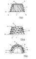
- the conically shaped outer shell 10 of the shell element 1 has, substantially transversely to the circumferential direction, a plurality of elongated openings 11 distributed over the surface of the outer shell, which extend at an angle to the axis of the shell element, almost over the height of the outer shell 10. 1, the openings 11 are inclined at an angle of 30 ° to the axis and at an angle of 10 ° in the direction of rotation, i.e. milled into the outer shell 10 at an angle of 10 to the radius of the outer shell 10. The latter angle can also be a few degrees smaller or larger.
- the angle of the openings 11 to the axis can generally be in the range from 20 to 40 *. Thread portions 12 are formed on the side of the outer shell facing the hip bone.
- the sections 12 are arranged in rows 13 at an angle to the axis and at an angle to the elongated openings 11.
- the thread sections 12 together form a double-start thread, which enables screwing into the hip bone with a relatively small torque. At the same time, it ensures a secure fit of the acetabulum.
- both the height and the length of the thread sections 12 increase from the proximal end 14 of the outer shell 10 to the distal end 15.
- the elongated openings 11 extending between the rows of thread sections 13 act like the groove of a tap.
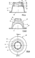
- a circumferential groove 16 is formed on the inside thereof.
- the proximal end 14 of the outer shell 10 is rounded at 17 on the outside and leaves an opening 18 formed by a circular edge 18 free.
- the inner shell 20 of the shell element 1 consists of a conical section 21 with a distal radial flange 22 and a proximal cylindrical section 24 connected to the section 21 via a shoulder 23.
- the conical section 21 forms a conical space 25 which adjoins a shoulder 26 ends.
- Adjoining the shoulder 26 is a conical inner section 28 which widens radially from distal to proximal and which is followed by a cylindrical section 29.
- Adjacent to the cylindrical section 29, a groove 30 is formed which is delimited by the ring edge 31 of an opening becomes.
- the inlay 40 has a hemispherical recess 41 for receiving a typical joint ball.
- the recess 41 is formed by the inner surfaces of a conical section 42 of the inlay.
- a radial flange 43 is formed at the distal end of the conical section 42.
- Extending from a shoulder 44 of the conical section 42 extends a substantially cylindrical section 45, on the outside of which a total of six projections 46 are formed, which are spaced apart in the circumferential direction according to FIG. 6.
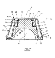
- the inner shell 20 is inserted into the outer shell 10.
- the flange 22 of the inner shell is received by the circumferential groove 16 of the outer shell, while the cylindrical section 24 of the inner shell fits into the opening 18 of the outer shell.
- an annular, conical intermediate space 50 is formed, in which before the shell element 1 is inserted bone substance can be stored in the hip bone through the elongated openings 11.
- a tool engages in the groove 30 of the inner shell. Due to the cutting thread formed from the thread sections 12 and the elongated openings 11, the shell element 1 can be screwed and anchored in the hip bone with the aid of a tool, not shown.
- the protrusions 46 When inserting the inlay 40 into the inner shell 20, e.g. from P.E. As is and is yielding, the protrusions 46 temporarily deform on the cylindrical portion 29 on the inside of the inner shell by being bent and pressed aside into the spaces therebetween until they engage the groove 30 and thereby lock the inlay in the inner shell.
- the shoulder 44 of the inlay engages with the shoulder 26 of the inner shell and the underside of the radial flange 22 of the inner shell rests on the radial flange 43 of the inlay, as does the distal end section of the outer shell 10.
- the cylindrical portion 45 of the inlay lies in the passageway 27 of the inner shell and is annularly surrounded by the cylindrical portion 24 of the inner shell which mates with the opening edge 18 of the outer shell so that the opening 18 is approximately from the proximal end surfaces of the inlay and the inner shell is covered at the level of the outside of the outer shell.
- hip bone material can grow into the space 50 through the openings 11 and grow together with the bone substance introduced there before the implantation, thus firmly anchoring the shell element in the hip bone.
Landscapes
- Health & Medical Sciences (AREA)
- Orthopedic Medicine & Surgery (AREA)
- Cardiology (AREA)
- Oral & Maxillofacial Surgery (AREA)
- Transplantation (AREA)
- Engineering & Computer Science (AREA)
- Biomedical Technology (AREA)
- Heart & Thoracic Surgery (AREA)
- Vascular Medicine (AREA)
- Life Sciences & Earth Sciences (AREA)
- Animal Behavior & Ethology (AREA)
- General Health & Medical Sciences (AREA)
- Public Health (AREA)
- Veterinary Medicine (AREA)
- Prostheses (AREA)
Abstract
Description
Die Erfindung bezieht sich auf ein Schalenelement zur Aufnahme einer Gelenkendoprothese, insbesondere einer Hüftgelenkendoprothese, nach dem Oberbegriff des Anspruchs 1.The invention relates to a shell element for receiving a joint endoprosthesis, in particular a hip joint endoprosthesis, according to the preamble of claim 1.
Endoprothesen für den Ersatz des Hüftgelenks sind seit langer Zeit bekannt. Für die Befestigung der Gelenkkugel der Endoprothese in dem Hüftknochen werden Gelenkpfannen verwendet. Aus der DE-OS 23 01 801 ist bekannt, die Gelenkpfanne aus einer Außen- und Innenkappe herzustellen, wobei die lösbar in der Außenkappe untergebrachte Innenkappe die Gelenkkugel aufnimmt. Aufgrund der ständigen, einseitigen Belastung durch die Kugel kommt es leicht zu Lockerungen der Gelenkpfanne. Die EP-A-0 303 006 offenbart, die Außenfläche des Pfannenkörpers zur Verbesserung des Verwachsens der Prothese mit dem Knochenmaterial zu verkugeln. Zur weiteren Verbesserung der Prothesenbefestigung am Knochen wird in der EP-A-0 329 019 vorgeschlagen, ein aus Außen-und Innenschale bestehendes, einschraubbares Schalenelement zu verwenden, bei dem runde oder langgestreckte Durchbrüche in der Außenschale vorgesehen sind. Vor Einsetzen des Schalenelementes in den Hüftknochen kann über diese Öffnungen Knochenmaterial in den zwischen Außen-und Innenschale ausgebildeten Zwischenraum eingefügt werden. Nach Implantation der Prothese kann körpereigenes Hüftknochenmaterial durch die Öffnungen mit dem eingebrachten Knochenmaterial verwachsen und so die Prothese fester mit dem Knochen verbinden. Zum Einschrauben des Schalenelementes sind auf der Außenseite der Außenschale Gewindegangabschnitte geformt, die an Nuten enden, die mit den Gewindeabschnitten ein Schneidgewinde bilden.Endoprostheses for the replacement of the hip joint have been known for a long time. Joint pans are used to fix the joint ball of the endoprosthesis in the hip bone. From DE-OS 23 01 801 it is known to produce the socket from an outer and inner cap, the inner cap releasably accommodated in the outer cap receiving the joint ball. Due to the constant, one-sided loading of the ball, the socket is easily loosened. EP-A-0 303 006 discloses sphering the outer surface of the socket body to improve the adherence of the prosthesis to the bone material. To further improve the prosthesis attachment to the bone, it is proposed in EP-A-0 329 019 to use a screw-in shell element consisting of an outer and inner shell, in which round or elongated openings are provided in the outer shell. Before inserting the shell element into the hip bone, bone material can be inserted into the space formed between the outer and inner shell through these openings. After implantation of the prosthesis, the body's own hip bone material can grow together with the inserted bone material through the openings and thus connect the prosthesis more firmly to the bone. To screw in the shell element, thread sections are formed on the outside of the outer shell, which end at grooves which form a cutting thread with the thread portions.
Aus dem Dargestellten ergibt sich, daß für ein Einschrauben des Schalenelementes ein selbstschneidendes Gewinde wichtig ist, und daß andererseits der Grad der Verwachsung des Hüftknochens mit dem Schalenelement für eine sichere und nicht wieder lösbare Befestigung des Schalenelementes und damit der Gelenkendoprothese an dem Knochen wesentlich ist.From what is shown it follows that a self-tapping thread is important for screwing in the shell element, and that on the other hand the degree of intergrowth of the hip bone with the shell element is essential for secure and non-releasable fastening of the shell element and thus the joint endoprosthesis to the bone.
Der Erfindung liegt daher die Aufgabe zugrunde, ein Schalenelement zu schaffen, bei dem das Einschrauben in die Knochenhöhlung und die wirksame Verwachsung mit den Knochen zwecks langdauernder fester Verbindung mit den Knochen noch verbessert ist.The invention is therefore based on the object of providing a shell element in which screwing into the bone cavity and effective adhesion to the bones for the purpose of long-term, firm connection to the bones is improved.
Diese Aufgabe wird gelöst durch die Merkmale des Kennzeichnungsteils des Anspruchs 1.This object is achieved by the features of the characterizing part of claim 1.
Bei dem erfindungsgemäßen Schalenelement sind im wesentlichen quer zur Umfangsrichtung und nahezu über die Höhe der Außenschale sich erstreckende, längliche Öffnungen vorgesehen, die zugleich als Nuten eines Schneidgewindes fungieren. Durch diese Anordnung der Öffnungen zwischen den sich im wesentlichen längs zur Umfangsrichtung erstreckenden Gewindegangabschnitten ist nicht nur gewährleistet, daß vor dem Einschrauben des Schalenelementes auf einfache Weise Knochensubstanz in den zwischen Innen-und Außenschale gebildeten Zwischenraum eingebracht werden kann. In vorteilhafter Weise kann darüber hinaus das beim Einschrauben des Schalenelementes abgetragene Knochenmaterial über die länglichen Öffnungen zwischen den Gewindegangabschnitten dem Zwischenraum zugeführt werden. Ein Herausfallen der in den Zwischenraum eingebrachten Knochensubstanz wird während der Operation verhindert.In the case of the shell element according to the invention, elongated openings are provided which extend essentially transversely to the circumferential direction and almost over the height of the outer shell and which simultaneously function as grooves of a cutting thread. This arrangement of the openings between the thread sections extending essentially longitudinally to the circumferential direction not only ensures that bone substance can be introduced in a simple manner into the intermediate space formed between the inner and outer shells before the shell element is screwed in. In addition, the bone material removed when the shell element is screwed in can advantageously be supplied to the intermediate space via the elongated openings between the thread sections. The bone substance introduced into the space is prevented from falling out during the operation.
Mit der erfindungsgemäßen Anordnung der Öffnungen ist es insbesondere möglich, diesen eine optimale Längserstreckung zu geben, nämlich nahezu über die gesamte Höhe der Außenschale, so daß nach erfolgter Implantation die Verwachsung des Knochens mit dem Schalenelement über eine relativ große Fläche erfolgen kann und somit das Schalenelement am Knochen sicher und dauerhaft befestigt ist.With the arrangement of the openings according to the invention, it is in particular possible to give them an optimal longitudinal extension, namely almost over the entire height of the outer shell, so that after the implantation has taken place, the bone can grow into the shell element over a relatively large area and thus the shell element is securely and permanently attached to the bone.
Nach einer bevorzugten Ausgestaltung der Erfindung ist das Schneidgewinde doppelgängig ausgebildet, wodurch sich ein zusätzlicher positiver Halteeffekt des Schalenelementes in dem Knochen ergibt.According to a preferred embodiment of the invention, the cutting thread is double-threaded, which results in an additional positive holding effect of the shell element in the bone.
Die länglichen Öffnungen sind nach einer weiteren Ausgestaltung der Erfindung schräg zur Gewindeachse, vorzugsweise unter einem Winkel von 30°, sowie unter einem Winkel zur Drehrichtung, vorzugsweise unter einem Winkel von 10°, in die Außenschale gefräst. Die angegebenen Winkelwerte sind nicht einschränkend zu verstehen; sie können nach oben oder unten variieren.According to a further embodiment of the invention, the elongated openings are milled into the outer shell obliquely to the thread axis, preferably at an angle of 30 °, and at an angle to the direction of rotation, preferably at an angle of 10 °. The given angle values are not to be understood as restrictive; they can vary up or down.
Zur Verbesserung des Einschraubmomentes nimmt die Höhe und die Länge der in Reihen winklig zur Schalenachse angeordneten Gewindegangabschnitte vom proximalen Ende der Außenschale zum distalen Ende hin zu. Dieser Ausgestaltung der Erfindung kommt in Kombination mit der erfindungsgemäßen Anordnung der länglichen Öffnungen sowie mit der doppelgängigen Auslegung des Schneidgewindes eine besondere Bedeutung zu, da es sich herausgestellt hat, daß diese Kombination das Einschrauben des Schalenelementes wesentlich erleichtert und das Schalenelement nach Implantation der Prothese sicher und dauernd befestigt ist.To improve the screwing-in torque, the height and the length of the thread sections arranged in rows at an angle to the shell axis increase from the proximal end of the outer shell to the distal end. This embodiment of the invention is of particular importance in combination with the arrangement of the elongated openings according to the invention and with the double-start design of the cutting thread, since it has been found that this combination considerably simplifies screwing in the shell element and the shell element after implantation of the prosthesis is safe and is permanently attached.
Außen- und Innenschale können einteilig gegossen werden. Alternativ werden beide Schalenteile jeweils getrennt gegossen, die Innenschale passend in die Außenschale gesteckt und beide Schalenteile zum Beispiel durch Kaltschweißung verbunden.Outer and inner shell can be cast in one piece. Alternatively, both shell parts are cast separately, the inner shell is inserted into the outer shell and both shell parts are joined, for example, by cold welding.
Bevorzugt wird nach einer weiteren Ausgestaltung der Erfindung eine konische Form der Außen-und Innenschale, wobei zum Einschrauben des Schalenelementes in den Hüftknochen an der Innenseite der Innenschale eine Nut ausgebildet ist, an der ein Werkzeug angreifen kann. Nach erfolgter Einschraubung wird ein passend geformtes Inlay in die Innenschale eingesetzt, welches über Vorsprünge mit der oben erwähnten Nut der Innenschale zusammenwirkt, wodurch eine effektive Verriegelung des Inlays in der Innenschale gegeben ist.According to a further embodiment of the invention, a conical shape of the outer and inner shell is preferred, with a groove being formed on the inside of the inner shell for screwing the shell element into the hip bone, and a tool can engage with this groove. After screwing in, a suitably shaped inlay is inserted into the inner shell, which cooperates with projections with the above-mentioned groove of the inner shell, thereby effectively locking the inlay in the inner shell.
Das aus Außenschale, Innenschale und Inlay zusammengesetzte Schalenelement wird distal von einem radialen, ringförmigen Flansch des Inlays, auf dem die Außenschale und Innenschale sich abstützen, und proximal von den annähernd auf einer Höhe liegenden, proximalen Endflächen der Außenschale, Innenschale und Inlay begrenzt.The shell element, which is composed of the outer shell, inner shell and inlay, is delimited distally by a radial, annular flange of the inlay on which the outer shell and inner shell are supported, and proximally by the proximal end surfaces of the outer shell, inner shell and inlay, which are approximately at a height.
Ein Ausführungsbeispiel wird nachfolgend anhand von Zeichnungen näher erläutert. Es zeigen:
- Fig. 1 einen Querschnitt durch eine Außenschale eines Schalenelementes nach der Erfindung,
- Fig. 2 eine Seitenansicht der Außenschale nach Fig. 1,
- Fig. 3 eine Draufsicht auf die Außenschale nach Fig. 1,
- Fig. 4 einen Querschnitt durch eine Innenschale eines Schalenelementes nach der Erfindung,
- Fig. 5 einen Querschnitt durch ein Inlay eines erfindungsgemäßen Schalenelementes,
- Fig. 6 eine Draufsicht auf das Inlay nach Fig. 5,
- Fig. 7 einen Schnitt durch ein aus Außenschale, Innenschale und Inlay zusammengesetztes Schalenelement nach der Erfindung.
- 1 shows a cross section through an outer shell of a shell element according to the invention,
- 2 is a side view of the outer shell of FIG. 1,
- 3 is a plan view of the outer shell of FIG. 1,
- 4 shows a cross section through an inner shell of a shell element according to the invention,
- 5 shows a cross section through an inlay of a shell element according to the invention,
- 6 is a plan view of the inlay of FIG. 5,
- Fig. 7 shows a section through a shell element composed of outer shell, inner shell and inlay according to the invention.
Das Schalenelement 1 besteht aus einer in einem Hüftknochen zu implantierenden Außenschale 10 und einer gelenkseitigen Innenschale 20, in die ein Inlay eingesetzt wird.The shell element 1 consists of an
Die konisch geformte Außenschale 10 des Schalenelementes 1 weist im wesentlichen quer zur Umfangsrichtung, mehrere, über die Fläche der Außenschale verteilte, längliche Öffnungen 11 auf, die sich winklig zur Achse des Schalenelements, nahezu über die Höhe der Außenschale 10 erstrekken. Gemäß Fig. 1 sind die Öffnungen 11 unter einem Winkel von 30° zur Achse und in einem Winkel von 10° in Drehrichtung geneigt, d.h. in einem Winkel von 10 zum Radius der Außenschale 10 in die Außenschale 10 gefräst. Der letztere Winkel kann auch einige Grade kleiner oder größer sein. Der Winkel der Öffnungen 11 zur Achse kann generall im Bereich von 20 bis 40* liegen. Auf der dem Hüftknochen zugewandten Seite der Außenschale sind Gewindegangabschnitte 12 ausgebildet. Nach Fig. 2 sind die Abschnitte 12 in Reihen 13 winklig zur Achse und im Winkel zu den länglichen Öffnungen 11 angeordnet. Die Gewindegangabschnitte 12 bilden zusammen ein doppelgängiges Gewinde, das ein Einschrauben in den Hüftknochen mit relativ kleinem Drehmoment ermöglicht. Gleichzeitig bewirkt es einen sicheren Sitz der Hüftpfanne. Wie insbesondere in Fig. 3 zu erkennen ist, nimmt sowohl die Höhe wie auch die Länge der Gewindegangabschnitte 12 vom proximalen Ende 14 der Außenschale 10 zum distalen Ende 15 hin zu. Die zwischen den Gewindegangabschnittsreihen 13 sich erstreckenden länglichen Öffnungen 11 wirken wie die Nut eines Gewindeschneiders. Am distalen Ende 15 der Außenschale ist an deren Innenseite eine Umfangsnut 16 geformt. Das proximale Ende 14 der Außenschale 10 ist außen bei 17 gerundet und läßt eine durch eine kreisförmige Kante 18 gebildete Öffnung 18 frei.The conically shaped
Nach Fig. 4 besteht die Innenschale 20 des Schalenelementes 1 aus einem konischen Abschnitt 21 mit einem distalen radialen Flansch 22 und einem über eine Schulter 23 mit dem Abschnitt 21 verbundenen proximalen zylindrischen Abschnitt 24. Der konische Abschnitt 21 bildet einen konischen Raum 25, der an einer Schulter 26 endet. An die Schulter 26 schließt sich ein konischer Innenabschnitt 28 an, der sich von distal nach proximal radial erweitert und der gefolgt wird von einem zylindrischen Abschnitt 29. Angrenzend an den zylindrischen Abschnitt 29 ist eine Nut 30 gebildet, die von dem Ringrand 31 einer Öffnung begrenzt wird.4, the
Das Inlay 40 weist nach Fig. 5 eine halbkugelige Ausnehmung 41 zur Aufnahme einer typischen Gelenkkugel auf. Die Ausnehmung 41 wird von den Innenflächen eines konischen Abschnitts 42 des Inlays geformt. Ein radialer Flansch 43 ist am distalen Ende des konischen Abschnitts 42 gebildet. Ausgehend von einer Schulter 44 des konischen Abschnitts 42 erstreckt sich ein im wesentlichen zylindrischer Abschnitt 45, an dessen Außenseite insgesamt sechs Vorsprünge 46 geformt sind, die gemäß Fig. 6 in Umfangsrichtung beabstandet sind.5, the
In Fig. 7 ist die Innenschale 20 in die Außenschale 10 eingesetzt. Der Flansch 22 der Innenschale wird von der Umfangsnut 16 der Außenschale aufgenommen, während der zylindrische Abschnitt 24 der Innenschale passend in die Öffnung 18 der Außenschale eingreift. Zwischen Außen- und Innenschale 10, 20, die einteilig geformt oder miteinander verschweißt sind, ist ein ringförmiger, konischer Zwischenraum 50 gebildet, in den vor dem Einsetzen des Schalenelementes 1 in den Hüftknochen Knochensubstanz durch die länglichen Öffnungen 11 eingelagert werden kann. Zum Einschrauben des aus Außen- und Innenschale zusammengesetzten Schalenelementes greift ein Werkzeug in die Nut 30 der Innenschale ein. Durch das aus den Gewindegangabschnitten 12 und den länglichen Öffnungen 11 gebildete Schneidgewinde läßt sich das Schalenelement 1 mit Hilfe eines nicht gezeigten Werkzeugs in den Hüftknochen einschrauben und verankern.7, the
Beim Einsetzen des Inlays 40 in die Innenschale 20, das z.B. aus P.E. Besteht und nachgebend ist, verformen sich die Vorsprünge 46 vorübergehend an dem zylindrischen Abschnitt 29 an der Innenseite der Innenschale, indem sie abgebogen und zur Seite gepreßt werden in die Abstände dazwischen bis sie in die Nut 30 eingreifen und so das Inlay in der Innenschale verriegeln. Die Schulter 44 des Inlays tritt in Eingriff mit der Schulter 26 der Innenschale und auf dem radialen Flansch 43 des Inlays liegt die Unterseite des radialen Flansches 22 der Innenschale an sowie nach außen der distale Endabschnitt der Außenschale 10.When inserting the
Der zylindrische Abschnitt 45 des Inlays liegt in dem Durchgang 27 der Innenschale und ist ringförmig von dem zylindrischen Abschnitt 24 der Innenschale umgeben, der in die Öffnungskante 18 der Außenschale passend eingreift, so daß die Öffnung 18 von den proximalen Endflächen des Inlays und der Innenschale annähernd auf Höhe der Außenseite der Außenschale abgedeckt wird.The
Nach Implantation einer Gelenkendoprothese kann in den Zwischenraum 50 Hüftknochenmaterial über die Öffnungen 11 einwachsen und mit der dort vor der Implantation eingebrachten Knochensubstanz zusammenwachsen und somit das Schalenelement fest im Hüftknochen verankern.After implantation of a joint endoprosthesis, hip bone material can grow into the
Claims (13)
Applications Claiming Priority (2)
| Application Number | Priority Date | Filing Date | Title |
|---|---|---|---|
| DE9014542U | 1990-10-20 | ||
| DE9014542U DE9014542U1 (en) | 1990-10-20 | 1990-10-20 | Shell element for receiving a joint endoprosthesis |
Publications (2)
| Publication Number | Publication Date |
|---|---|
| EP0482320A1 true EP0482320A1 (en) | 1992-04-29 |
| EP0482320B1 EP0482320B1 (en) | 1996-09-11 |
Family
ID=6858571
Family Applications (1)
| Application Number | Title | Priority Date | Filing Date |
|---|---|---|---|
| EP91114637A Expired - Lifetime EP0482320B1 (en) | 1990-10-20 | 1991-08-30 | Acetubular cup for receiving a joint endoprosthesis |
Country Status (7)
| Country | Link |
|---|---|
| US (1) | US5147407A (en) |
| EP (1) | EP0482320B1 (en) |
| JP (1) | JPH04300539A (en) |
| AT (1) | ATE142462T1 (en) |
| CA (1) | CA2051793A1 (en) |
| DE (2) | DE9014542U1 (en) |
| ES (1) | ES2091842T3 (en) |
Cited By (17)
| Publication number | Priority date | Publication date | Assignee | Title |
|---|---|---|---|---|
| US5370703A (en) * | 1992-09-01 | 1994-12-06 | Sulzer Medizinaltechnik Ag | Double-cup hipjoint socket suitable for use in revision |
| EP0640325A1 (en) * | 1993-08-30 | 1995-03-01 | SULZER Medizinaltechnik AG | Multi-part artificial acetabular cup and hip joint prosthesis with such a cup |
| EP0649641A2 (en) * | 1993-10-21 | 1995-04-26 | CERASIV GmbH INNOVATIVES KERAMIK-ENGINEERING | Conical hip joint acetabular cup |
| US5458650A (en) * | 1993-03-30 | 1995-10-17 | Tornier S.A. | Elastically deformable cotyloidal prosthesis |
| EP0694294A1 (en) * | 1994-07-28 | 1996-01-31 | Werner Hermann | Socket of a joint prosthesis |
| US5549699A (en) * | 1994-10-21 | 1996-08-27 | Osteotech Of Virginia | Bony fixation and support of a prosthesis |
| DE19520495C1 (en) * | 1995-06-03 | 1996-11-14 | Werner Scholz | Artificial hip joint socket with metal outer half shell fixed into hip bone |
| DE19520468C1 (en) * | 1995-06-03 | 1996-11-28 | Werner Scholz | Artificial acetabular cup |
| EP0773007A1 (en) * | 1995-11-07 | 1997-05-14 | Aesculap Ag | Endoprosthetic acetabular cup |
| EP0943304A3 (en) * | 1998-03-17 | 2000-10-11 | Biomet Merck Deutschland GmbH | Threaded acetabular cup for a hip joint prosthesis |
| DE10000521A1 (en) * | 1999-07-15 | 2001-03-01 | Ceramtec Ag | Ceramic sandwich insert for an artificial hip joint |
| DE10118985A1 (en) * | 2001-04-18 | 2002-11-21 | Implantcast Gmbh | Acetabular system |
| DE10159677A1 (en) * | 2001-12-05 | 2003-06-26 | Aesculap Ag & Co Kg | Hip replacement comprises outer shell ring spanned inside by support surface of flat center and conical sides sitting close to joint insert setdown surfaces as installed. |
| WO2010091995A1 (en) * | 2009-02-11 | 2010-08-19 | Ceramtec Ag | Ceramic ball socket insert having inverse-conical guide pins |
| US8123815B2 (en) | 2008-11-24 | 2012-02-28 | Biomet Manufacturing Corp. | Multiple bearing acetabular prosthesis |
| US8308810B2 (en) | 2009-07-14 | 2012-11-13 | Biomet Manufacturing Corp. | Multiple bearing acetabular prosthesis |
| FR3048356A1 (en) * | 2016-03-01 | 2017-09-08 | T O | COTYLOID ELEMENT OF HIP PROSTHESIS, COMPRISING RELIEFS OF AID FOR IMPACTION |
Families Citing this family (29)
| Publication number | Priority date | Publication date | Assignee | Title |
|---|---|---|---|---|
| DE9014542U1 (en) * | 1990-10-20 | 1991-01-03 | Howmedica GmbH, 2314 Schönkirchen | Shell element for receiving a joint endoprosthesis |
| DE4211346C2 (en) * | 1992-04-04 | 1995-08-10 | S & G Implants Gmbh | Cup of a hip joint endoprosthesis |
| US5549700A (en) * | 1993-09-07 | 1996-08-27 | Ortho Development Corporation | Segmented prosthetic articulation |
| DE69526094T2 (en) * | 1994-09-15 | 2002-11-21 | Surgical Dynamics, Inc. | CONICAL FUSION CAGE |
| DE4437479A1 (en) * | 1994-10-20 | 1996-05-02 | Volker Prof Dr Echtermeyer | Endoprosthesis for hip or knee joint |
| SE9600208D0 (en) | 1996-01-19 | 1996-01-19 | Astra Ab | Fixture and prosthesis including the same |
| DE19644015C1 (en) * | 1996-10-31 | 1998-01-02 | Roswitha Quetin | Rotary bone grater used in dental and surgical implantation operations |
| DE19757799A1 (en) * | 1997-12-29 | 1999-07-01 | Gerd Hoermansdoerfer | Process for hobbling and preferred application of the process |
| US7323013B2 (en) * | 1998-04-14 | 2008-01-29 | Encore Medical Asset Corporation | Differential porosity prosthetic hip system |
| US20040010319A1 (en) * | 1998-04-14 | 2004-01-15 | Osteoimplant Technology Inc. | Intrinsic stability in a total hip stem |
| AUPQ070399A0 (en) * | 1999-06-02 | 1999-06-24 | Cryptych Pty Ltd | Acetabular component of total hip replacement assembly |
| DE19926923A1 (en) * | 1999-06-14 | 2000-12-21 | Ceramtec Ag | Modular socket for a ball joint prosthesis |
| JP4193177B2 (en) * | 2002-02-20 | 2008-12-10 | ジンマー インコーポレーテッド | Prosthesis and tibial implant device for knee arthroplasty |
| US7182786B2 (en) * | 2002-04-25 | 2007-02-27 | Zimmer Technology, Inc. | Modular bone implant, tool, and method |
| US7799086B2 (en) * | 2002-04-25 | 2010-09-21 | Zimmer Technology, Inc. | Modular bone implant, tools, and method |
| US20040102852A1 (en) | 2002-11-22 | 2004-05-27 | Johnson Erin M. | Modular knee prosthesis |
| FR2858209B1 (en) * | 2003-07-30 | 2006-06-02 | Depuy France | ACETABULAR IMPLANT AND METHOD OF MANUFACTURING THE IMPLANT |
| GB0321582D0 (en) * | 2003-09-15 | 2003-10-15 | Benoist Girard Sas | Prosthetic acetabular cup and prosthetic femoral joint incorporating such a cup |
| US7267693B1 (en) * | 2003-12-08 | 2007-09-11 | Orthopedic Source, Inc. | Locking ring for liner of acetabular cup |
| JP4637168B2 (en) * | 2004-03-31 | 2011-02-23 | サイオン オーソピディクス アクチェンゲゼルシャフト | Double shell implant for cementless fixation of artificial joints |
| DE102004057709A1 (en) * | 2004-11-09 | 2006-06-08 | Hörmansdörfer, Gerd | Self-tapping screw-in body e.g. for artificial acetabulum, has outer surface is partially curved or bent in threaded area, and has thread interrupted by flute |
| DE102004053944A1 (en) * | 2004-11-09 | 2006-05-11 | Hörmansdörfer, Gerd | Replacement hip socket has thread on its outside, inner surface of each thread remaining parallel to lip of socket while angle of outer edge increases with distance from lip |
| FR2882921B1 (en) * | 2005-03-11 | 2008-02-01 | Michel Timoteo | COTYLOID BONE FUSION PROSTHESIS |
| EP1787603A1 (en) | 2005-11-18 | 2007-05-23 | Zimmer GmbH | Basis-platform for an artificial joint |
| US20070203583A1 (en) | 2006-02-28 | 2007-08-30 | Biomet Manufacturing Corp. | Method and apparatus for aligning a taper lock connection |
| US20080255574A1 (en) * | 2007-04-13 | 2008-10-16 | Zimmer Technology, Inc. | Instrument for insertion of prosthetic components |
| US20110015752A1 (en) * | 2009-07-14 | 2011-01-20 | Biomet Manufacturing Corp. | System and Method for Acetabular Cup |
| EP2502604B1 (en) * | 2011-03-21 | 2013-09-25 | Jossi Holding AG | Joint socket implant |
| EP2815726B1 (en) * | 2013-06-19 | 2015-08-12 | Arthrex, Inc. | Humerus implant |
Citations (7)
| Publication number | Priority date | Publication date | Assignee | Title |
|---|---|---|---|---|
| EP0179736A2 (en) * | 1984-10-23 | 1986-04-30 | Mecron Medizinische Produkte Gmbh | Support element for an artificial acetabular cup |
| EP0214885A1 (en) * | 1985-08-12 | 1987-03-18 | Jean-Alain Epinette | Acetabular cup for a hip joint to be implanted without cement |
| DE8710796U1 (en) * | 1987-08-04 | 1987-11-19 | Mecron Medizinische Produkte Gmbh, 1000 Berlin | Ring-shaped support element for an artificial hip socket |
| FR2617040A1 (en) * | 1987-06-23 | 1988-12-30 | Erato | Acetabular prosthesis |
| FR2622432A1 (en) * | 1987-11-03 | 1989-05-05 | Emile Letournel | Screwable cotyle ring for hip prosthesis |
| EP0329019A1 (en) * | 1988-02-11 | 1989-08-23 | Howmedica GmbH | Acetabular cup for a joint prosthesis |
| DE9014542U1 (en) * | 1990-10-20 | 1991-01-03 | Howmedica GmbH, 2314 Schönkirchen | Shell element for receiving a joint endoprosthesis |
Family Cites Families (21)
| Publication number | Priority date | Publication date | Assignee | Title |
|---|---|---|---|---|
| US3848272A (en) * | 1972-01-13 | 1974-11-19 | United States Surgical Corp | Artificial hip joint |
| CH568753A5 (en) * | 1973-08-31 | 1975-11-14 | Oscobal Ag | |
| FR2429009A1 (en) * | 1978-06-21 | 1980-01-18 | Roux Christiane | PROSTHESIS FOR ARTICULATION, PARTICULARLY COXO-FEMORAL, ARTIFICIAL |
| DE2950536A1 (en) * | 1979-12-15 | 1981-07-02 | Howmedica International, Inc. Zweigniederlassung Kiel, 2300 Kiel | Artificial acetabulum - with outer shell of ceramics and inner shell of polyethylene |
| DE3147707A1 (en) * | 1981-05-18 | 1982-12-23 | Mecron Medizinische Produkte Gmbh, 1000 Berlin | Part of a hip prosthesis |
| DE3129174A1 (en) * | 1981-07-21 | 1983-02-03 | Mecron Med Prod Gmbh | Acetabular prosthesis |
| US4662891A (en) * | 1983-11-21 | 1987-05-05 | Joint Medical Products Corporation | Fixation elements for artificial joints |
| GB2154141B (en) * | 1984-02-14 | 1987-06-24 | Howmedica | Acetabular cup for use with hip prosthesis |
| DE3535959C1 (en) * | 1985-10-09 | 1987-04-09 | Orthoplant Endoprothetik | Hip joint endoprosthesis cup |
| CA1290099C (en) * | 1986-01-21 | 1991-10-08 | Thomas H. Mallory | Porous-coated artificial joints |
| CH668901A5 (en) * | 1986-02-18 | 1989-02-15 | Sulzer Ag | ENDOPROSTHETATION FOR A HIP ACTION. |
| FR2595562B1 (en) * | 1986-03-13 | 1992-08-28 | Rhenter Jean Luc | PROSTHESIS CUP |
| CH669903A5 (en) * | 1986-04-15 | 1989-04-28 | Sulzer Ag | |
| ATE57299T1 (en) * | 1986-07-09 | 1990-10-15 | Chenil Cont Spa | WEIGHT-BEARING JOINT PROSTHESIS WITH SHOCK ABSORBER. |
| US4795469A (en) * | 1986-07-23 | 1989-01-03 | Indong Oh | Threaded acetabular cup and method |
| CH671687A5 (en) * | 1987-03-30 | 1989-09-29 | Sulzer Ag | |
| CH672418A5 (en) * | 1987-06-25 | 1989-11-30 | Sulzer Ag | |
| DE8711039U1 (en) * | 1987-08-13 | 1987-10-15 | Howmedica GmbH, 2314 Schönkirchen | Joint socket for a hip joint endoprosthesis |
| ATE72392T1 (en) * | 1987-11-09 | 1992-02-15 | Intraplant Ag | ARTICULATING ENDOPROSTHESIS. |
| FR2630907B1 (en) * | 1988-05-03 | 1997-07-11 | Biomecanique Integree | SCREWED COTYL, ESPECIALLY FOR "HIP" TYPE PROSTHESIS |
| DE8810783U1 (en) * | 1988-06-06 | 1988-10-20 | Mecron Medizinische Produkte Gmbh, 1000 Berlin | Screw cup as part of a hip joint prosthesis |
-
1990
- 1990-10-20 DE DE9014542U patent/DE9014542U1/en not_active Expired - Lifetime
-
1991
- 1991-08-30 ES ES91114637T patent/ES2091842T3/en not_active Expired - Lifetime
- 1991-08-30 DE DE59108174T patent/DE59108174D1/en not_active Expired - Fee Related
- 1991-08-30 EP EP91114637A patent/EP0482320B1/en not_active Expired - Lifetime
- 1991-08-30 AT AT91114637T patent/ATE142462T1/en not_active IP Right Cessation
- 1991-09-18 CA CA002051793A patent/CA2051793A1/en not_active Abandoned
- 1991-10-15 US US07/776,122 patent/US5147407A/en not_active Expired - Fee Related
- 1991-10-16 JP JP3298277A patent/JPH04300539A/en active Pending
Patent Citations (7)
| Publication number | Priority date | Publication date | Assignee | Title |
|---|---|---|---|---|
| EP0179736A2 (en) * | 1984-10-23 | 1986-04-30 | Mecron Medizinische Produkte Gmbh | Support element for an artificial acetabular cup |
| EP0214885A1 (en) * | 1985-08-12 | 1987-03-18 | Jean-Alain Epinette | Acetabular cup for a hip joint to be implanted without cement |
| FR2617040A1 (en) * | 1987-06-23 | 1988-12-30 | Erato | Acetabular prosthesis |
| DE8710796U1 (en) * | 1987-08-04 | 1987-11-19 | Mecron Medizinische Produkte Gmbh, 1000 Berlin | Ring-shaped support element for an artificial hip socket |
| FR2622432A1 (en) * | 1987-11-03 | 1989-05-05 | Emile Letournel | Screwable cotyle ring for hip prosthesis |
| EP0329019A1 (en) * | 1988-02-11 | 1989-08-23 | Howmedica GmbH | Acetabular cup for a joint prosthesis |
| DE9014542U1 (en) * | 1990-10-20 | 1991-01-03 | Howmedica GmbH, 2314 Schönkirchen | Shell element for receiving a joint endoprosthesis |
Cited By (26)
| Publication number | Priority date | Publication date | Assignee | Title |
|---|---|---|---|---|
| US5370703A (en) * | 1992-09-01 | 1994-12-06 | Sulzer Medizinaltechnik Ag | Double-cup hipjoint socket suitable for use in revision |
| US5458650A (en) * | 1993-03-30 | 1995-10-17 | Tornier S.A. | Elastically deformable cotyloidal prosthesis |
| EP0640325A1 (en) * | 1993-08-30 | 1995-03-01 | SULZER Medizinaltechnik AG | Multi-part artificial acetabular cup and hip joint prosthesis with such a cup |
| US5549695A (en) * | 1993-08-30 | 1996-08-27 | Sulzer Medizinaltechnic Ag | Composite artificial socket and hip joint prosthesis |
| EP0649641A2 (en) * | 1993-10-21 | 1995-04-26 | CERASIV GmbH INNOVATIVES KERAMIK-ENGINEERING | Conical hip joint acetabular cup |
| EP0649641A3 (en) * | 1993-10-21 | 1995-05-24 | Cerasiv Gmbh | |
| US5879397A (en) * | 1993-10-21 | 1999-03-09 | Cerasiv, Gmbh Innovative Keramik Engineers | Tapered hip joint socket |
| EP0694294A1 (en) * | 1994-07-28 | 1996-01-31 | Werner Hermann | Socket of a joint prosthesis |
| US5549699A (en) * | 1994-10-21 | 1996-08-27 | Osteotech Of Virginia | Bony fixation and support of a prosthesis |
| DE19520495C1 (en) * | 1995-06-03 | 1996-11-14 | Werner Scholz | Artificial hip joint socket with metal outer half shell fixed into hip bone |
| DE19520468C1 (en) * | 1995-06-03 | 1996-11-28 | Werner Scholz | Artificial acetabular cup |
| EP0773007A1 (en) * | 1995-11-07 | 1997-05-14 | Aesculap Ag | Endoprosthetic acetabular cup |
| EP0943304A3 (en) * | 1998-03-17 | 2000-10-11 | Biomet Merck Deutschland GmbH | Threaded acetabular cup for a hip joint prosthesis |
| DE10000521A1 (en) * | 1999-07-15 | 2001-03-01 | Ceramtec Ag | Ceramic sandwich insert for an artificial hip joint |
| DE10118985A1 (en) * | 2001-04-18 | 2002-11-21 | Implantcast Gmbh | Acetabular system |
| DE10118985C2 (en) * | 2001-04-18 | 2003-06-26 | Implantcast Gmbh | Acetabular system |
| DE10159677A1 (en) * | 2001-12-05 | 2003-06-26 | Aesculap Ag & Co Kg | Hip replacement comprises outer shell ring spanned inside by support surface of flat center and conical sides sitting close to joint insert setdown surfaces as installed. |
| DE10159677B4 (en) * | 2001-12-05 | 2006-10-12 | Aesculap Ag & Co. Kg | Endoprosthetic acetabulum |
| US8123815B2 (en) | 2008-11-24 | 2012-02-28 | Biomet Manufacturing Corp. | Multiple bearing acetabular prosthesis |
| US9445903B2 (en) | 2008-11-24 | 2016-09-20 | Biomet Manufacturing, Llc | Multi-bearing acetabular prosthesis |
| CN102341064A (en) * | 2009-02-11 | 2012-02-01 | 塞拉姆泰克公司 | Ceramic ball socket insert having inverse-conical guide pins |
| CN102341064B (en) * | 2009-02-11 | 2014-09-17 | 塞拉姆泰克公司 | Ceramic ball socket insert having inverse-conical guide pins |
| WO2010091995A1 (en) * | 2009-02-11 | 2010-08-19 | Ceramtec Ag | Ceramic ball socket insert having inverse-conical guide pins |
| US8308810B2 (en) | 2009-07-14 | 2012-11-13 | Biomet Manufacturing Corp. | Multiple bearing acetabular prosthesis |
| US9445904B2 (en) | 2009-07-14 | 2016-09-20 | Biomet Manufacturing, Llc | Multiple bearing acetabular prosthesis |
| FR3048356A1 (en) * | 2016-03-01 | 2017-09-08 | T O | COTYLOID ELEMENT OF HIP PROSTHESIS, COMPRISING RELIEFS OF AID FOR IMPACTION |
Also Published As
| Publication number | Publication date |
|---|---|
| CA2051793A1 (en) | 1992-04-21 |
| JPH04300539A (en) | 1992-10-23 |
| ATE142462T1 (en) | 1996-09-15 |
| US5147407A (en) | 1992-09-15 |
| ES2091842T3 (en) | 1996-11-16 |
| EP0482320B1 (en) | 1996-09-11 |
| DE59108174D1 (en) | 1996-10-17 |
| DE9014542U1 (en) | 1991-01-03 |
Similar Documents
| Publication | Publication Date | Title |
|---|---|---|
| EP0482320B1 (en) | Acetubular cup for receiving a joint endoprosthesis | |
| EP0329019B1 (en) | Acetabular cup for a joint prosthesis | |
| EP0144574B1 (en) | Composite hip endoprosthesis | |
| EP0265712A1 (en) | Acetabular component for a total hip prosthesis | |
| AT390183B (en) | BONE IMPLANT FOR ENDOPROTHESIS | |
| EP0666068A1 (en) | Outer shell a hip joint prosthesis acetabular cup having at least two shells and hip joint prosthesis with such an outer shell | |
| EP0065482A2 (en) | Artificial hip socket | |
| DE2610922A1 (en) | STEM FOR KNEE JOINT ENDOPROSTHESES | |
| DE19731442A1 (en) | Cup for a joint endoprosthesis | |
| DE2039731B2 (en) | Prosthetic socket for femoral heads | |
| EP0554210A1 (en) | Set of parts for an artificial hip acetabular cup | |
| DE2950536A1 (en) | Artificial acetabulum - with outer shell of ceramics and inner shell of polyethylene | |
| DE4135310A1 (en) | CEMENT-FREE ENDOPROTHESIS | |
| EP0845251A1 (en) | Construction kit for a modular femoral head prosthesis, especially a reoperation prosthesis, and femoral head prosthesis made from such a kit | |
| DE69202222T2 (en) | Acetabular cup for hip prosthesis. | |
| DE3325448A1 (en) | Hip socket endoprosthesis | |
| EP0827386B1 (en) | Endoprosthesis for a metatarso-phalangeal joint | |
| EP1411869B1 (en) | Artificial joint prosthesis | |
| DE19532898A1 (en) | Artificial acetabular cup for hip joint | |
| DE69809857T2 (en) | Acetabular cup implant with plug | |
| DE19714050C2 (en) | Hip cup with anchoring peg | |
| DE3819948C2 (en) | ||
| EP0617931A2 (en) | Artificial hip acetabular cup | |
| DE10308141B4 (en) | Extension sleeve for a modular joint prosthesis | |
| DE4223373C2 (en) | Endoprosthesis socket for knee joints and process for its manufacture |
Legal Events
| Date | Code | Title | Description |
|---|---|---|---|
| PUAI | Public reference made under article 153(3) epc to a published international application that has entered the european phase |
Free format text: ORIGINAL CODE: 0009012 |
|
| AK | Designated contracting states |
Kind code of ref document: A1 Designated state(s): AT CH DE ES FR GB IT LI NL |
|
| 17P | Request for examination filed |
Effective date: 19920508 |
|
| 17Q | First examination report despatched |
Effective date: 19931020 |
|
| GRAG | Despatch of communication of intention to grant |
Free format text: ORIGINAL CODE: EPIDOS AGRA |
|
| GRAH | Despatch of communication of intention to grant a patent |
Free format text: ORIGINAL CODE: EPIDOS IGRA |
|
| GRAH | Despatch of communication of intention to grant a patent |
Free format text: ORIGINAL CODE: EPIDOS IGRA |
|
| GRAA | (expected) grant |
Free format text: ORIGINAL CODE: 0009210 |
|
| AK | Designated contracting states |
Kind code of ref document: B1 Designated state(s): AT CH DE ES FR GB IT LI NL |
|
| REF | Corresponds to: |
Ref document number: 142462 Country of ref document: AT Date of ref document: 19960915 Kind code of ref document: T |
|
| REG | Reference to a national code |
Ref country code: CH Ref legal event code: NV Representative=s name: ISLER & PEDRAZZINI AG |
|
| GBT | Gb: translation of ep patent filed (gb section 77(6)(a)/1977) |
Effective date: 19960912 |
|
| REF | Corresponds to: |
Ref document number: 59108174 Country of ref document: DE Date of ref document: 19961017 |
|
| ITF | It: translation for a ep patent filed | ||
| REG | Reference to a national code |
Ref country code: ES Ref legal event code: FG2A Ref document number: 2091842 Country of ref document: ES Kind code of ref document: T3 |
|
| ET | Fr: translation filed | ||
| PGFP | Annual fee paid to national office [announced via postgrant information from national office to epo] |
Ref country code: AT Payment date: 19970709 Year of fee payment: 7 |
|
| PGFP | Annual fee paid to national office [announced via postgrant information from national office to epo] |
Ref country code: CH Payment date: 19970715 Year of fee payment: 7 |
|
| PLBE | No opposition filed within time limit |
Free format text: ORIGINAL CODE: 0009261 |
|
| STAA | Information on the status of an ep patent application or granted ep patent |
Free format text: STATUS: NO OPPOSITION FILED WITHIN TIME LIMIT |
|
| PGFP | Annual fee paid to national office [announced via postgrant information from national office to epo] |
Ref country code: FR Payment date: 19970728 Year of fee payment: 7 |
|
| PGFP | Annual fee paid to national office [announced via postgrant information from national office to epo] |
Ref country code: ES Payment date: 19970806 Year of fee payment: 7 |
|
| PG25 | Lapsed in a contracting state [announced via postgrant information from national office to epo] |
Ref country code: GB Free format text: LAPSE BECAUSE OF NON-PAYMENT OF DUE FEES Effective date: 19970830 |
|
| PGFP | Annual fee paid to national office [announced via postgrant information from national office to epo] |
Ref country code: NL Payment date: 19970831 Year of fee payment: 7 |
|
| 26N | No opposition filed | ||
| PGFP | Annual fee paid to national office [announced via postgrant information from national office to epo] |
Ref country code: DE Payment date: 19971022 Year of fee payment: 7 |
|
| GBPC | Gb: european patent ceased through non-payment of renewal fee |
Effective date: 19970830 |
|
| PG25 | Lapsed in a contracting state [announced via postgrant information from national office to epo] |
Ref country code: AT Free format text: LAPSE BECAUSE OF NON-PAYMENT OF DUE FEES Effective date: 19980830 |
|
| PG25 | Lapsed in a contracting state [announced via postgrant information from national office to epo] |
Ref country code: LI Free format text: LAPSE BECAUSE OF NON-PAYMENT OF DUE FEES Effective date: 19980831 Ref country code: ES Free format text: LAPSE BECAUSE OF THE APPLICANT RENOUNCES Effective date: 19980831 Ref country code: CH Free format text: LAPSE BECAUSE OF NON-PAYMENT OF DUE FEES Effective date: 19980831 |
|
| PG25 | Lapsed in a contracting state [announced via postgrant information from national office to epo] |
Ref country code: NL Free format text: LAPSE BECAUSE OF NON-PAYMENT OF DUE FEES Effective date: 19990301 |
|
| REG | Reference to a national code |
Ref country code: CH Ref legal event code: PL |
|
| PG25 | Lapsed in a contracting state [announced via postgrant information from national office to epo] |
Ref country code: FR Free format text: LAPSE BECAUSE OF NON-PAYMENT OF DUE FEES Effective date: 19990430 |
|
| NLV4 | Nl: lapsed or anulled due to non-payment of the annual fee |
Effective date: 19990301 |
|
| PG25 | Lapsed in a contracting state [announced via postgrant information from national office to epo] |
Ref country code: DE Free format text: LAPSE BECAUSE OF NON-PAYMENT OF DUE FEES Effective date: 19990601 |
|
| REG | Reference to a national code |
Ref country code: FR Ref legal event code: ST |
|
| REG | Reference to a national code |
Ref country code: ES Ref legal event code: FD2A Effective date: 20001102 |
|
| PG25 | Lapsed in a contracting state [announced via postgrant information from national office to epo] |
Ref country code: IT Free format text: LAPSE BECAUSE OF NON-PAYMENT OF DUE FEES;WARNING: LAPSES OF ITALIAN PATENTS WITH EFFECTIVE DATE BEFORE 2007 MAY HAVE OCCURRED AT ANY TIME BEFORE 2007. THE CORRECT EFFECTIVE DATE MAY BE DIFFERENT FROM THE ONE RECORDED. Effective date: 20050830 |