EP0065210B1 - Verfahren zur Aufbereitung elektrischer Signale mit einer digitalen Filteranordnung - Google Patents
Verfahren zur Aufbereitung elektrischer Signale mit einer digitalen Filteranordnung Download PDFInfo
- Publication number
- EP0065210B1 EP0065210B1 EP82103859A EP82103859A EP0065210B1 EP 0065210 B1 EP0065210 B1 EP 0065210B1 EP 82103859 A EP82103859 A EP 82103859A EP 82103859 A EP82103859 A EP 82103859A EP 0065210 B1 EP0065210 B1 EP 0065210B1
- Authority
- EP
- European Patent Office
- Prior art keywords
- signals
- signal
- sub
- spectral
- spectral sub
- Prior art date
- Legal status (The legal status is an assumption and is not a legal conclusion. Google has not performed a legal analysis and makes no representation as to the accuracy of the status listed.)
- Expired
Links
Images
Classifications
-
- H—ELECTRICITY
- H04—ELECTRIC COMMUNICATION TECHNIQUE
- H04K—SECRET COMMUNICATION; JAMMING OF COMMUNICATION
- H04K1/00—Secret communication
- H04K1/04—Secret communication by frequency scrambling, i.e. by transposing or inverting parts of the frequency band or by inverting the whole band
-
- G—PHYSICS
- G10—MUSICAL INSTRUMENTS; ACOUSTICS
- G10L—SPEECH ANALYSIS OR SYNTHESIS; SPEECH RECOGNITION; SPEECH OR VOICE PROCESSING; SPEECH OR AUDIO CODING OR DECODING
- G10L21/00—Processing of the speech or voice signal to produce another audible or non-audible signal, e.g. visual or tactile, in order to modify its quality or its intelligibility
- G10L21/02—Speech enhancement, e.g. noise reduction or echo cancellation
-
- H—ELECTRICITY
- H03—ELECTRONIC CIRCUITRY
- H03H—IMPEDANCE NETWORKS, e.g. RESONANT CIRCUITS; RESONATORS
- H03H17/00—Networks using digital techniques
- H03H17/02—Frequency selective networks
- H03H17/0283—Filters characterised by the filter structure
- H03H17/0286—Combinations of filter structures
- H03H17/0288—Recursive, non-recursive, ladder, lattice structures
-
- H—ELECTRICITY
- H04—ELECTRIC COMMUNICATION TECHNIQUE
- H04B—TRANSMISSION
- H04B1/00—Details of transmission systems, not covered by a single one of groups H04B3/00 - H04B13/00; Details of transmission systems not characterised by the medium used for transmission
- H04B1/66—Details of transmission systems, not covered by a single one of groups H04B3/00 - H04B13/00; Details of transmission systems not characterised by the medium used for transmission for reducing bandwidth of signals; for improving efficiency of transmission
- H04B1/667—Details of transmission systems, not covered by a single one of groups H04B3/00 - H04B13/00; Details of transmission systems not characterised by the medium used for transmission for reducing bandwidth of signals; for improving efficiency of transmission using a division in frequency subbands
-
- H—ELECTRICITY
- H04—ELECTRIC COMMUNICATION TECHNIQUE
- H04B—TRANSMISSION
- H04B3/00—Line transmission systems
- H04B3/02—Details
- H04B3/20—Reducing echo effects or singing; Opening or closing transmitting path; Conditioning for transmission in one direction or the other
- H04B3/21—Reducing echo effects or singing; Opening or closing transmitting path; Conditioning for transmission in one direction or the other using a set of bandfilters
-
- G—PHYSICS
- G10—MUSICAL INSTRUMENTS; ACOUSTICS
- G10L—SPEECH ANALYSIS OR SYNTHESIS; SPEECH RECOGNITION; SPEECH OR VOICE PROCESSING; SPEECH OR AUDIO CODING OR DECODING
- G10L25/00—Speech or voice analysis techniques not restricted to a single one of groups G10L15/00 - G10L21/00
- G10L25/03—Speech or voice analysis techniques not restricted to a single one of groups G10L15/00 - G10L21/00 characterised by the type of extracted parameters
- G10L25/18—Speech or voice analysis techniques not restricted to a single one of groups G10L15/00 - G10L21/00 characterised by the type of extracted parameters the extracted parameters being spectral information of each sub-band
Definitions
- the invention relates to a method for processing electrical signals with a digital filter arrangement in which one or more input signals are split into spectral partial signals by means of a decimating technique, these spectral partial signals are processed and combined to form the output signal by means of an interpolating technique.
- the type of signal processing of a signal is to be understood in the sense of linear filtering or signal improvement or echo or feedback compensation or signal concealment or any combination thereof.
- the processing of the signal in a digital filter arrangement is time-discrete.
- a signal improvement is necessary if an additive disturbance is superimposed on the signal.
- This interference can be caused by acoustic background noise or by electrical interference in the transmission channel.
- the steady-state intervals i.e. the speech pauses and thus the parameters of the disturbance are recognized.
- the filter coefficients of an optimal filter are calculated (US-A-4025721), which minimizes the remaining residual error according to certain criteria.
- Another time-domain filter method is known from DT-B-2749132, in which an adaptive, digital transversal filter is used for signal improvement, the filter coefficients being set according to a gradient algorithm and the estimate signal formed in this way being intended to represent the best possible reproduction of the original signal.
- spectral subtraction Another method for signal improvement is the so-called spectral subtraction.
- the spectral transformation FFT Fast Fourier Transform
- the magnitude (or power) spectrum is essentially corrected by subtracting an estimated magnitude (power) spectrum of the disturbance.
- the phase of the disturbed signal is then added and an inverse FFT is carried out.
- This known method can be found, for example, from a treatise in TEEE-Transactions, vol. ASSP-26, 1978, pages 471-472 and vol. ASSP-27, pages 113-120.
- the signal spectrum can be split into several frequency bands, these can be interchanged and / or the frequency can be reversed. This enables a transmission channel to be secured against unauthorized eavesdropping (e.g. DT-B-1273002).
- the invention is based on the object of realizing a digital filter arrangement with little expenditure of resources, in which the various types of signal processing can be selected in any combination.
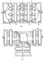
- the digital filter arrangement according to FIG. 1 contains a device 1 by means of which an input signal u is split into spectral partial signals Vy in the form of complex low-pass signals. By indexing with the index v a running parameter (channel), e.g. B. Vy spectral partial signal for the vth channel. These spectral partial signals Vy are each processed in a device 2.
- the processing in the device 2 depending on the intended use, prepares the input signal u in such a way that filtering and signal improvement or echo and feedback compensation or signal obfuscation or any combination thereof can be achieved. It proves to be advantageous that the structure of the digital filter arrangement can be retained despite different uses.
- the output signals W ⁇ of the device 2 are combined in a device 3 to form an output signal ⁇ in such a way that the output signal s according to the purpose z. B. filtered.
- the input signal u which, for. B. consists of a speech signal s and an additively superimposed interference signal n, using a filter bank (device 1) split into frequency bands.
- a filter bank (device 1) split into frequency bands.
- An advantageous embodiment of the filter bank is known for example from Signal Processing, Volume 2, 1980, pages 55-65. This consists of a so-called poly-phase network 11, which is connected to an FFT processor 12.
- the mode of operation of such a device 1 can be described by M equidistant channels with constant bandwidth.
- a complex-valued low-pass signal V ⁇ is produced at each of the outputs in accordance with quadrature bandpass filtering with conversion to the low-pass position and with simultaneous clock reduction.
- This clock reduction or decimation of a sampling frequency for the input signal u can be described by a rotating switch 13 arranged on the input side of the digital filter arrangement.
- an input memory can be provided for this.
- the digital filter arrangement can advantageously be operated with the theoretically lowest possible clock frequency and the computational effort can be reduced.
- the polyphase network 11 contains a number of sub-filters 14, the coefficients of which can be set, in accordance with the number M of the spectral partial signals Vy.
- the choice of the coefficients of the partial filters 14 can be described by the choice of the coefficients of a recursive or non-recursive prototype low-pass filter with its impulse response h TP .
- the spectral resolution is determined by the frequency response of the prototype low-pass filter.
- the output signals v of the partial filters 14 ⁇ ( ⁇ -filtered component signals v) of Polyphasennetzwerkes 11 can be described by the following equation
- the clock can be reduced by a factor r ⁇ M.
- the filtered partial signals v ⁇ are converted into complex-value low-pass signals Vy with the aid of the computing method of the discrete Fourier transformation in the FFT processor 12.
- the following equation applies to the complex low-pass signal Vy
- the discrete Fourier transformation does not mean the meaning of a spectral transformation but rather a complex calculation rule for the formation of linear combinations of the time signals v ⁇ .
- Each of the complex-value low-pass signals Vy can be subjected to adaptive, complex-value filtering for noise reduction.
- this filtering can also be carried out as level control.
- the level control preferably an adaptive level control, the real and imaginary parts can be controlled independently of one another.
- devices 21 are provided in device 2, with which, for example, a level factor c ⁇ common for each channel can be selected. The following equations then apply to the complex-value output signals Wy of the devices 21 with a level factor cy or
- the short-term powers of the interference signals N ⁇ are calculated in the speech pauses, the time constants of the averaging being controlled by a speech pause detector.
- the constants ⁇ i or the window lengths can be selected, for example, on the assumption of stationary interference, that the short-term powers of the complex-value time signals W ⁇ in each channel correspond to the short-term powers of the undisturbed signal components Sy after level control.
- the resultant, complex-valued signals W ⁇ are used to convert the output signal s by an inverse operation in an FFT processor 31 which is connected to a polyphase network 34 and by inverse polyphase filtering.
- an FFT processor 31 which is connected to a polyphase network 34 and by inverse polyphase filtering.
- the clock frequency of the samples is increased again to the original clock frequency for the input signal u.
- This clock increase at the output of the digital filter arrangement is described in FIG. 1 with a switch 33.
- the equations below apply to the inverse operations
- spectral partial signals V ⁇ can be separated into real and imaginary parts, the use of adaptive level control for real and imaginary parts, for example, is possible.
- Recursive and non-recursive prototype filters can be used for partial filters 14 and 32, respectively. With the aid of the method according to the invention, a highly effective noise reduction with minimal distortion of the speech signal with a small number of channels M can be achieved.
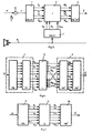
- FIG. 2 shows a further embodiment for the digital filter in the event that a reference signal r, which is correlated with the disturbance n, is available.
- the input signal in this case the reference signal r, is split into spectral partial signals Ry by means of the decimating technique.
- the common level factor c ⁇ can be determined according to the following equation
- 2 is determined from the quotient of the short-term powers of the interference signal N ⁇ (see equation (8)) and the reference signal Ry in the speech pauses.
- FIG. 3 shows the use of the digital filter arrangement according to the invention for echo and feedback compensation.
- An echo speech signal g is additively superimposed on the speech signal s in a microphone 5.
- An estimate signal s is formed from the microphone signal (s + g) in the digital filter arrangement by the method steps: splitting the microphone signal into spectral partial signals by means of a decimating technique, processing these spectral partial signals, for example by real-value, adaptive level control and composition of these spectral partial signals by means of interpolating Technology were applied.
- a reference signal is used to derive the adaptive, real-value level factors, which in the present case is identical to a loudspeaker signal g.
- the mean quadratic transfer function can be measured according to the following equation by measuring the short-term powers of the spectral partial signals Gy and Gy be determined. It is also possible to feed a test signal, which is, for example, white noise or a multi-frequency signal, for measurement instead of the loudspeaker signal g before the start of the conversation.
- FIG. 4 shows the use of the digital filter arrangement according to the invention for signal concealment.
- devices e.g. DT-C-1273 002
- the speech frequency band is divided into several subbands of the same width and the subbands are interchanged.
- the band switching method can be used.
- an exchanger selects n from 2n modulators, each of which is assigned a fixed carrier frequency.
- signal obfuscation can be achieved by interchanging and / or inversion of frequency bands.
- the complex-valued low-pass signals Vy of the device 1 are first z. B. for noise reduction, as described with reference to Figure 1, the device 2 supplied.
- the complex time signals Wy at the outputs of the device 2 are staggered in terms of their frequencies.
- the vth band is inversed by interchanging the signals W ⁇ and W M- ⁇ or by reversing the sign of the imaginary parts of W v and W M- ⁇ .
- a band swapping can be achieved by swapping W ⁇ with W ⁇ and W M- ⁇ with W M- ⁇ for ⁇ ⁇ ⁇ .
- FIG. 4 shows the exchange for the complex time signals W 1 with W 2 and the inversion of W 3 .
- FIG. 5 shows a further exemplary embodiment for signal concealment by means of the digital filter arrangement.
- the processing and assignment of the complex time signals Wy can be represented by vectorial mapping. This makes it possible to combine the process steps FFT (Fast Fourier Transformation), processing, assignment and inverse FFT into a matrix multiplication.
- FFT Fast Fourier Transformation
- a vector v whose components are the filtered partial signals v 0 , v 1 ... v M-1 is, by multiplication with a matrix 6, directly on the vector w with the components w 0 , w 1 , ... w M-1 , according to the following equation pictured.
- the different types of signal processing e.g. Filtering, signal improvement (with or without reference), echo or feedback compensation can be implemented simultaneously or in any combination by means of a digital filter arrangement according to FIGS. 3 and 4.
- g and r can either be added first and then fed to the device 3, or a plurality of separate devices 4 can be provided.
Applications Claiming Priority (2)
| Application Number | Priority Date | Filing Date | Title |
|---|---|---|---|
| DE3118473A DE3118473A1 (de) | 1981-05-09 | 1981-05-09 | Verfahren zur aufbereitung elektrischer signale mit einer digitalen filteranordnung |
| DE3118473 | 1981-05-09 |
Publications (3)
| Publication Number | Publication Date |
|---|---|
| EP0065210A2 EP0065210A2 (de) | 1982-11-24 |
| EP0065210A3 EP0065210A3 (en) | 1984-09-05 |
| EP0065210B1 true EP0065210B1 (de) | 1987-01-28 |
Family
ID=6131908
Family Applications (1)
| Application Number | Title | Priority Date | Filing Date |
|---|---|---|---|
| EP82103859A Expired EP0065210B1 (de) | 1981-05-09 | 1982-05-05 | Verfahren zur Aufbereitung elektrischer Signale mit einer digitalen Filteranordnung |
Country Status (5)
| Country | Link |
|---|---|
| US (1) | US4623980A (ja) |
| EP (1) | EP0065210B1 (ja) |
| JP (1) | JPS5830219A (ja) |
| CA (1) | CA1201178A (ja) |
| DE (2) | DE3118473A1 (ja) |
Families Citing this family (45)
| Publication number | Priority date | Publication date | Assignee | Title |
|---|---|---|---|---|
| DE3230391A1 (de) * | 1982-08-14 | 1984-02-16 | Philips Kommunikations Industrie AG, 8500 Nürnberg | Verfahren zur signalverbesserung von gestoerten sprachsignalen |
| ATE37972T1 (de) * | 1983-07-14 | 1988-10-15 | Ant Nachrichtentech | Verfahren zur anpassung von zwei systemen mit unterschiedlicher abtastrate. |
| FR2577084B1 (fr) * | 1985-02-01 | 1987-03-20 | Trt Telecom Radio Electr | Systeme de bancs de filtres d'analyse et de synthese d'un signal |
| US4698769A (en) * | 1985-02-04 | 1987-10-06 | American Telephone And Telegraph Company | Supervisory audio tone detection in a radio channel |
| US4868773A (en) * | 1985-03-15 | 1989-09-19 | Purdue Research Foundation | Digital filtering by threshold decomposition |
| DE3510352C1 (de) * | 1985-03-22 | 1986-09-11 | ANT Nachrichtentechnik GmbH, 7150 Backnang | Gegensprech-Übertragungseinrichtung |
| DE3510573A1 (de) * | 1985-03-23 | 1986-09-25 | Philips Patentverwaltung | Digitale analyse-synthese-filterbank mit maximaler taktreduktion |
| US4709344A (en) * | 1985-10-02 | 1987-11-24 | Motorola, Inc. | Programmable multifrequency digital tone receiver |
| GB2181318B (en) * | 1985-10-04 | 1989-12-28 | Sony Corp | Two-dimensional finite impulse response filters |
| IT1181998B (it) * | 1985-12-24 | 1987-09-30 | Selenia Ind Elettroniche | Elaboratore di segnale per radar ad apertura sintetica particolarmente adatto al calcolo parallelo |
| US4825396A (en) * | 1986-02-14 | 1989-04-25 | Siemens Aktiengesellschaft | Digital circuit for sampling rate variation and signal filtering and method for constructing the circuit |
| JPS6345933A (ja) * | 1986-04-15 | 1988-02-26 | Nec Corp | 秘話装置 |
| JPS63196450A (ja) * | 1987-02-04 | 1988-08-15 | Kiyuwatsuto Kk | 可動トレイ型ソ−タ |
| CA1288182C (en) * | 1987-06-02 | 1991-08-27 | Mitsuhiro Azuma | Secret speech equipment |
| US4912767A (en) * | 1988-03-14 | 1990-03-27 | International Business Machines Corporation | Distributed noise cancellation system |
| JP2870756B2 (ja) * | 1988-04-20 | 1999-03-17 | 株式会社リコー | 空間フィルタ画像処理装置 |
| DE3834188A1 (de) * | 1988-10-07 | 1990-04-12 | Thomson Brandt Gmbh | Filter |
| JP2774296B2 (ja) * | 1989-01-20 | 1998-07-09 | キヤノン株式会社 | 情報処理方法及びその装置 |
| US5029184A (en) * | 1990-01-24 | 1991-07-02 | Harris Corporation | Low probability of intercept communication system |
| CA2036078C (en) * | 1990-02-21 | 1994-07-26 | Fumio Amano | Sub-band acoustic echo canceller |
| GB2241853A (en) * | 1990-03-08 | 1991-09-11 | British Aerospace | Digital signal processing apparatus comprising architectures for digital multiplexing and demultiplexing. |
| DE4021787A1 (de) * | 1990-07-09 | 1992-01-16 | Telefunken Electronic Gmbh | Elektro-akustisches system |
| US5305307A (en) * | 1991-01-04 | 1994-04-19 | Picturetel Corporation | Adaptive acoustic echo canceller having means for reducing or eliminating echo in a plurality of signal bandwidths |
| GB9104186D0 (en) * | 1991-02-28 | 1991-04-17 | British Aerospace | Apparatus for and method of digital signal processing |
| FR2680924B1 (fr) * | 1991-09-03 | 1997-06-06 | France Telecom | Procede de filtrage adapte d'un signal transforme en sous-bandes, et dispositif de filtrage correspondant. |
| US5282222A (en) * | 1992-03-31 | 1994-01-25 | Michel Fattouche | Method and apparatus for multiple access between transceivers in wireless communications using OFDM spread spectrum |
| USRE37802E1 (en) | 1992-03-31 | 2002-07-23 | Wi-Lan Inc. | Multicode direct sequence spread spectrum |
| AU689439B2 (en) * | 1992-07-07 | 1998-04-02 | Lake Technology Limited | Digital filter having high accuracy and efficiency |
| US5606575A (en) * | 1993-10-29 | 1997-02-25 | Airnet Communications Corporation | FFT-based channelizer and combiner employing residue-adder-implemented phase advance |
| US5535240A (en) * | 1993-10-29 | 1996-07-09 | Airnet Communications Corporation | Transceiver apparatus employing wideband FFT channelizer and inverse FFT combiner for multichannel communication network |
| FR2739736B1 (fr) * | 1995-10-05 | 1997-12-05 | Jean Laroche | Procede de reduction des pre-echos ou post-echos affectant des enregistrements audio |
| US6192068B1 (en) | 1996-10-03 | 2001-02-20 | Wi-Lan Inc. | Multicode spread spectrum communications system |
| US5926455A (en) * | 1996-12-19 | 1999-07-20 | Lucent Technologies Inc. | Recursive filters for polyphase structures |
| US6130943A (en) * | 1996-12-23 | 2000-10-10 | Mci Communications Corporation | Method and apparatus for suppressing echo in telephony |
| US5933421A (en) * | 1997-02-06 | 1999-08-03 | At&T Wireless Services Inc. | Method for frequency division duplex communications |
| SG71035A1 (en) * | 1997-08-01 | 2000-03-21 | Bitwave Pte Ltd | Acoustic echo canceller |
| US6026123A (en) * | 1997-08-02 | 2000-02-15 | Williams; Thomas H. | Digital transmission system with high immunity to dynamic linear distortion |
| EP1072089B1 (en) * | 1998-03-25 | 2011-03-09 | Dolby Laboratories Licensing Corp. | Audio signal processing method and apparatus |
| US6604071B1 (en) * | 1999-02-09 | 2003-08-05 | At&T Corp. | Speech enhancement with gain limitations based on speech activity |
| GB2348350B (en) * | 1999-03-26 | 2004-02-18 | Mitel Corp | Echo cancelling/suppression for handsets |
| US6718038B1 (en) * | 2000-07-27 | 2004-04-06 | The United States Of America As Represented By The National Security Agency | Cryptographic method using modified fractional fourier transform kernel |
| WO2002086755A1 (en) * | 2001-04-24 | 2002-10-31 | California Institute Of Technology | Method and apparatus for parallel signal processing |
| FR2834563B1 (fr) * | 2002-01-08 | 2004-04-02 | Thales Sa | Procede de suppression de signaux radioelectriques pulses et dispositif de mise en oeuvre du procede |
| KR100454886B1 (ko) * | 2002-02-01 | 2004-11-06 | 한국과학기술원 | 독립 성분 분석을 이용한 여파기 적응 알고리즘의 필터뱅크 접근 방법 |
| DE10352537A1 (de) * | 2003-11-11 | 2005-06-09 | Siemens Ag | Verfahren und Filterbank zur spektralen Modifikation eines digitalen Signals |
Family Cites Families (5)
| Publication number | Priority date | Publication date | Assignee | Title |
|---|---|---|---|---|
| DE1273002B (de) * | 1963-09-11 | 1968-07-18 | Siemens Ag | Einrichtung zur verschluesselten UEbertragung von Sprachsignalen durch Vertauschung von Teilbaendern |
| DE2426451B2 (de) * | 1974-05-31 | 1976-10-28 | Siemens AG, 1000 Berlin und 8000 München | Schaltungsanordnung fuer einrichtungen zur teilbandvertauschung |
| JPS5227239A (en) * | 1975-08-26 | 1977-03-01 | Toshiba Corp | Filter |
| JPS5234647A (en) * | 1975-09-12 | 1977-03-16 | Hitachi Ltd | Frequency sampling filter |
| DE3032397A1 (de) * | 1980-08-28 | 1982-03-11 | Battelle-Institut E.V., 6000 Frankfurt | Schaltungsanordnung fuer ein einstellbares elektrisches filter |
-
1981
- 1981-05-09 DE DE3118473A patent/DE3118473A1/de active Granted
-
1982
- 1982-05-05 EP EP82103859A patent/EP0065210B1/de not_active Expired
- 1982-05-05 DE DE8282103859T patent/DE3275340D1/de not_active Expired
- 1982-05-07 JP JP57075535A patent/JPS5830219A/ja active Pending
- 1982-05-07 CA CA000402552A patent/CA1201178A/en not_active Expired
-
1985
- 1985-03-08 US US06/709,358 patent/US4623980A/en not_active Expired - Fee Related
Also Published As
| Publication number | Publication date |
|---|---|
| CA1201178A (en) | 1986-02-25 |
| US4623980A (en) | 1986-11-18 |
| DE3118473C2 (ja) | 1987-02-05 |
| DE3118473A1 (de) | 1982-11-25 |
| EP0065210A3 (en) | 1984-09-05 |
| DE3275340D1 (en) | 1987-03-05 |
| JPS5830219A (ja) | 1983-02-22 |
| EP0065210A2 (de) | 1982-11-24 |
Similar Documents
| Publication | Publication Date | Title |
|---|---|---|
| EP0065210B1 (de) | Verfahren zur Aufbereitung elektrischer Signale mit einer digitalen Filteranordnung | |
| DE3510660C2 (ja) | ||
| EP0200239B1 (de) | Digitale Polyphasen-Filterbank mit maximaler Taktreduktion | |
| DE3405010A1 (de) | Vorrichtung zur erzeugung eines verzoegerungsschaetzwertes fuer eine echoausloescheinrichtung | |
| EP1525576B1 (de) | Vorrichtung und verfahren zum erzeugen einer komplexen spektraldarstellung eines zeitdiskreten signals | |
| DE19956088A1 (de) | Einseiten-Unterband-Filter | |
| DE2622423B2 (de) | Elektrische Anordnung zur Übertragung oder Speicherung eines Sprachoder Tonsignals in kodierter Form | |
| DE2707936A1 (de) | Einseitenband-frequenzmultiplex- uebertragungssystem | |
| EP1239455A2 (de) | Verfahren und Anordnung zur Durchführung einer an die Übertragungsfunktion menschilcher Sinnesorgane angepassten Fourier Transformation sowie darauf basierende Vorrichtungen zur Geräuschreduktion und Spracherkennung | |
| DE4427124A1 (de) | Anordnung zur Kommunikation mit einem Teilnehmer | |
| EP1755110A2 (de) | Verfahren und Vorrichtung zur adaptiven Reduktion von Rausch- und Hintergrundsignalen in einem sprachverarbeitenden System | |
| EP0577653B1 (de) | Verfahren zum ermitteln der übertragungseigenschaften einer elektrischen leitung | |
| DE3230391C2 (ja) | ||
| DE102007018585B4 (de) | Vorrichtung und Verfahren zur Ermittlung und Kompensation von Störsignalen in einem Nachrichtenübertragungssystem | |
| DE4328139A1 (de) | Schaltungsanordnung zur Echoauslöschung | |
| EP0855806B1 (de) | Echosperre für ein Spracheingabe Dialogsystem | |
| DE19729521B4 (de) | Verfahren und Vorrichtung zur Störgeräusch- und Echounterdrückung | |
| AT371639B (de) | Verfahren zur aufbereitung elektrischer signale mit einer digitalen filteranordnung | |
| EP0075311B1 (de) | Anordnung zur Übertragung von Sprache nach dem Kanalvocoderprinzip | |
| EP0402519A1 (de) | Verfahren und Anordnung zur Verbesserung des Dynamikbereichs eines adaptiven rekursiven Netzwerks zur Verarbeitung zeitdiskreter Signale | |
| DE3029518A1 (de) | Puls-doppler-radar mit einer schaltungsanordnung zur kohaerenten integration | |
| DE112012006266B4 (de) | Echolöschvorrichtung | |
| EP1958429B1 (de) | Verfahren zur steuerung des adaptionsverhaltens einer akustischen echokompensation | |
| DE19601405B4 (de) | Verfahren und Vorrichtung zur Systemidentifikation und Echokompensation in Übertragungssystemen | |
| DE3732047A1 (de) | Verfahren zur umcodierung von kanalvocoder-parameter in lpc-vocoder-parameter |
Legal Events
| Date | Code | Title | Description |
|---|---|---|---|
| PUAI | Public reference made under article 153(3) epc to a published international application that has entered the european phase |
Free format text: ORIGINAL CODE: 0009012 |
|
| AK | Designated contracting states |
Designated state(s): CH DE FR GB LI NL SE |
|
| 17P | Request for examination filed |
Effective date: 19821018 |
|
| PUAL | Search report despatched |
Free format text: ORIGINAL CODE: 0009013 |
|
| AK | Designated contracting states |
Designated state(s): CH DE FR GB LI NL SE |
|
| 17Q | First examination report despatched |
Effective date: 19860220 |
|
| GRAA | (expected) grant |
Free format text: ORIGINAL CODE: 0009210 |
|
| AK | Designated contracting states |
Kind code of ref document: B1 Designated state(s): CH DE FR GB LI NL SE |
|
| REF | Corresponds to: |
Ref document number: 3275340 Country of ref document: DE Date of ref document: 19870305 |
|
| PGFP | Annual fee paid to national office [announced via postgrant information from national office to epo] |
Ref country code: NL Payment date: 19870531 Year of fee payment: 6 |
|
| ET | Fr: translation filed | ||
| PLBE | No opposition filed within time limit |
Free format text: ORIGINAL CODE: 0009261 |
|
| STAA | Information on the status of an ep patent application or granted ep patent |
Free format text: STATUS: NO OPPOSITION FILED WITHIN TIME LIMIT |
|
| 26N | No opposition filed | ||
| PG25 | Lapsed in a contracting state [announced via postgrant information from national office to epo] |
Ref country code: LI Effective date: 19890531 Ref country code: CH Effective date: 19890531 |
|
| PG25 | Lapsed in a contracting state [announced via postgrant information from national office to epo] |
Ref country code: NL Effective date: 19891201 |
|
| NLV4 | Nl: lapsed or anulled due to non-payment of the annual fee | ||
| REG | Reference to a national code |
Ref country code: CH Ref legal event code: PL |
|
| PGFP | Annual fee paid to national office [announced via postgrant information from national office to epo] |
Ref country code: DE Payment date: 19900725 Year of fee payment: 9 |
|
| PG25 | Lapsed in a contracting state [announced via postgrant information from national office to epo] |
Ref country code: DE Effective date: 19920303 |
|
| PGFP | Annual fee paid to national office [announced via postgrant information from national office to epo] |
Ref country code: SE Payment date: 19920525 Year of fee payment: 11 |
|
| PGFP | Annual fee paid to national office [announced via postgrant information from national office to epo] |
Ref country code: GB Payment date: 19930430 Year of fee payment: 12 |
|
| PG25 | Lapsed in a contracting state [announced via postgrant information from national office to epo] |
Ref country code: SE Effective date: 19930506 |
|
| PGFP | Annual fee paid to national office [announced via postgrant information from national office to epo] |
Ref country code: FR Payment date: 19930526 Year of fee payment: 12 |
|
| PG25 | Lapsed in a contracting state [announced via postgrant information from national office to epo] |
Ref country code: GB Effective date: 19940505 |
|
| GBPC | Gb: european patent ceased through non-payment of renewal fee |
Effective date: 19940505 |
|
| EUG | Se: european patent has lapsed |
Ref document number: 82103859.3 Effective date: 19931210 |
|
| PG25 | Lapsed in a contracting state [announced via postgrant information from national office to epo] |
Ref country code: FR Effective date: 19950131 |
|
| REG | Reference to a national code |
Ref country code: FR Ref legal event code: ST |