US4698769A - Supervisory audio tone detection in a radio channel - Google Patents
Supervisory audio tone detection in a radio channel Download PDFInfo
- Publication number
- US4698769A US4698769A US06/698,095 US69809585A US4698769A US 4698769 A US4698769 A US 4698769A US 69809585 A US69809585 A US 69809585A US 4698769 A US4698769 A US 4698769A
- Authority
- US
- United States
- Prior art keywords
- tones
- tone
- sat
- path
- threshold
- Prior art date
- Legal status (The legal status is an assumption and is not a legal conclusion. Google has not performed a legal analysis and makes no representation as to the accuracy of the status listed.)
- Expired - Lifetime
Links
- 238000001514 detection method Methods 0.000 title description 8
- 238000000034 method Methods 0.000 claims description 15
- 230000014509 gene expression Effects 0.000 claims description 9
- 238000005070 sampling Methods 0.000 claims description 4
- 230000010354 integration Effects 0.000 description 6
- 230000001413 cellular effect Effects 0.000 description 4
- 238000005259 measurement Methods 0.000 description 4
- 230000003190 augmentative effect Effects 0.000 description 2
- 239000000872 buffer Substances 0.000 description 2
- 238000010586 diagram Methods 0.000 description 2
- 230000006870 function Effects 0.000 description 2
- 230000035945 sensitivity Effects 0.000 description 2
- 238000004590 computer program Methods 0.000 description 1
- 238000005094 computer simulation Methods 0.000 description 1
- 239000013078 crystal Substances 0.000 description 1
- 238000005516 engineering process Methods 0.000 description 1
- 238000005562 fading Methods 0.000 description 1
- 230000036039 immunity Effects 0.000 description 1
- 238000012544 monitoring process Methods 0.000 description 1
- 230000011664 signaling Effects 0.000 description 1
- 230000001360 synchronised effect Effects 0.000 description 1
Images


Classifications
-
- H—ELECTRICITY
- H04—ELECTRIC COMMUNICATION TECHNIQUE
- H04Q—SELECTING
- H04Q1/00—Details of selecting apparatus or arrangements
- H04Q1/18—Electrical details
- H04Q1/30—Signalling arrangements; Manipulation of signalling currents
- H04Q1/44—Signalling arrangements; Manipulation of signalling currents using alternate current
- H04Q1/442—Signalling arrangements; Manipulation of signalling currents using alternate current with out-of-voice band signalling frequencies
Definitions
- This invention relates to cellular mobile radio telephone systems and, in particular, to rapid and reliable detection of audio control tones in the presence of severe signal-to-noise conditions.
- supervision is the process of detecting customer intiated changes in the switch-hook state of a telephone.
- the aforesaid cellular system uses a combination of a signaling tone (ST) burst and a continuous out-of-band, supervisory audio tone (SAT).
- ST signaling tone
- SAT supervisory audio tone
- Three SAT's are set aside at 5970, 6000, and 6030 Hz; any one is used at a given cell site.
- a mobile unit receives a SAT from a cell site and returns it to the cell site. It is important for the cell site to compute reliably the SAT returned from the mobile unit within a predetermined period.
- This invention teaches the rapid and accurate computation of the SAT from a variety of sources concurrently.
- a decoder confirms detection of the corresponding SAT. More particularly, the SAT which is received from a mobile unit is converted from analog to digital form and appropriately limited for noise immunity.
- the SAT is bifurcated into two paths. The tone in one path is multiplied by a cosine function of time to derive the real component of a complex number and the tone in the other path is multiplied by a sine function to derive the imaginary component of the complex number.
- a series of the real components of the generated complex numbers is accumulated in an inphase data accumulator and the corresponding imaginary components of the complex numbers are accumulated in a (quad) quadrature phase accumulator.
- DFT discrete Fourier transform
- An advantage of the present invention is that it provides reliable detection of SAT in a fading channel.
- the prior art typically relied on phase lock loops which become unlocked during fades or other types of signal interruption.
- methods based on analog filters were excessively sensitive to tolerances and the like in view of the excessively high selectively, or Q, required.
- a further advantage of the present invention as disclosed is that the digital nature of the implementation allows it to be effectively multiplexed, by sampling received signals discontinuously over several antenna faces thus encountering a type of interruption, or by sampling continuously with apparent concurrency over several discrete channels.
- distinct parallel equipment including receivers, for each antenna face would be required if the signal detection were done by phase lock loops.
- a further advantage of the present invention is that by nature of the digital implementation under stored program control, parameters of the detection process such as selectivity may be dynamically altered in real time.
- FIG. 1 is a block diagram of apparatus implementing the present invention
- FIG. 2 is a graph of the expression ⁇ Fr 2 +Fi 2 ;
- FIG. 3 is a graph of the expression
- FIG. 4 is a line drawing showing the various computations to be done within a predetermined period to determine a supervisory audio tone
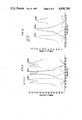
- FIGS. 5 through 9 are flow charts showing the various steps in the computation of supervisory audio tones.
- FIG. 10 is a block diagram of another apparatus implementation of the present invention.
- FIG. 1 there is shown apparatus for receiving and detecting the presence of supervisory audio tones (SAT's) from a mobile unit. More particularly, omnidirectional antenna 10, and directional antennas 12, 14 and 16 receive signals from a mobile telephone unit (not shown). Although only four antennas are described, it is clear that this number may be changed. As stated in the background of this application, omnidirectional antennas are used to receive signals from all directions. But when a system grows, the omnidirectional antenna configuration is augmented by three directional antennas: alpha, beta, and gamma; each antenna serving a separate region of angular width 120 degrees. Switch 18 switches each of the aforesaid antennas in turn to receiver 20. After being filtered by element 21, analog signals are converted to digital signals in converter 22. A crystal oscillator 24 drives a binary counter 26 which provides clock signals at different synchronous subrates to the various elements and will not be described in detail because such technology is well known.
- SAT's supervisory audio tones
- ROM 30 read only memory
- Limiter 32 is a return to zero limiter of the type disclosed in a patent application having Ser. No. 497,228, filed May 23, 1983 by D. J. Thomson, one of the inventors of the present application which is now U.S. Pat. No. 4,596,024, issued on June 17, 1986.
- the frequency of the received signal is extracted by conceptually feeding the output from limiter 32 to two multiplication circuits 34 and 36.
- circuit 36 has two inputs: the output from limiter 32 and cos ( ⁇ c t).
- the output signals from circuit 34 are numerically integrated in element 42 of quadrature accumulator 40 and the output signals from circuit 36 are likewise numerically integrated in element 44 of data accumulator 46.
- the aforesaid signals from the multiplier circuits 34 and 36 are integrated over an interval from 0 to T (approximately one millisecond).
- the first integrator 42 in cooperation with processor 50 performs a discrete approximation to the analog operation: ##EQU1## and the second integrator 44, again cooperating with processor 50, likewise performs a discrete approximation to the analog operation: ##EQU2##
- Each integral is over T seconds and is repeated every T k seconds.
- the integration time T is approximately one millisecond and the time between integrations, T k , is (66.6 over 8) milliseconds.
- Each of these integrals over T seconds comprises twelve subintegrals which are computed in hardware accumulators 42 and 44. The output signals from accumulators 42 and 44 are combined by processor 50 in the manner described hereinbelow. Each of these subintegrals comprise sixty-four samples and extend for one half-cycle of the 6 KHz signal, that is, for 1/12,000 of a second.
- each subintegral formed by summing sixty-four consecutive output signals from multipliers 34 and 36 at a spacing of 1/64 ⁇ 12,000 of a second, that is, 1.302 microseconds, and so have a duration of T/12 seconds. Twelve consecutive half-cycle results are combined in a manner described below to give the approximation to the integrals in equations (1) and (2). The two integrals of the sine and cosine products are combined to provide a complex number, as described hereinabove. These operations are repeated N times (N 8 in the preferred embodiment) to provide N complex numbers which are stored in buffer storage unit 52 of processor 50.
- DFT discrete Fourier transform
- T acts as a scaling factor
- T acts as a scaling factor
- the greater the T the greater the sensitivity and selectivity
- ##EQU5## is a phase factor and is ignored in this frequency analysis
- ##EQU6## is a distortion factor.
- the distortion factor is approximately one, so that it can be neglected.
- N complex numbers can be obtained which correspond to N discrete points of Ae j ⁇ .sbsp.o t , where each point is separated in time by T k ; that is: ##EQU8##
- processor 50 in computing the complex numbers received from quadrature accumulator 40 is shown in FIGS. 5 through 9. These steps are sufficiently detailed and are not repeated here.
- the goal is to determine eight complex numbers.
- the real component corresponds to the cos ( ⁇ t) component and the imaginary part corresponds to the sin ( ⁇ t) component.
- Each complex number is determined by entering numbers, the aforementioned subintegrals, from both data accumulator 40 and from quadrature accumulator 46 twelve times into corresponding processor registers. Each time a number is entered from aforesaid accumulators, it is either added to or subtracted from a running sum which is maintained in two corresponding processor data and quadrature registers.
- a lookup table located in an integrated circuit comprising the multiplier circuits 34 and 36 has half cycle information. In order to obtain information spanning a whole cycle, it is necessary to invert the sign of data from alternate half cycles. The use of lookup tables is well known and will not be further described.
- y(k) corresponds to the imaginary part of the kth number
- FR(n) corresponds to the real part of the nth Fourier coefficient
- FI(n) corresponds to the imaginary part of the nth Fourier coefficient.
- the output is sent over path 57 to a cell site controller (not shown).
- the aforesaid steps are repeated for each of the three directional antennas. Note, however, that this does not imply that measurements and decisions for four antennas requires four times the time required for one.
- M 2, an integer.
- Each of the aforesaid complex numbered samples is maintained as thirty-two bits; sixteen bits by way of the real part and sixteen bits by way of the imaginary part.
- the real part x k is given by ##EQU12##
- the imaginary part y k is given by ##EQU13## where, p nk is the nth sample from data accumulator 46, and q nk is the nth sample from the quadrature accumulator 40 during the kth time interval.
- Each of the p's and q's is the sum of sixty-four products of s(t) with cosine computed in data accumulator 46 and sixty-four products of s(t) with sine computed in quadrature accumulator 40 over the same half cycle of the 6 KHz clock.
- the DFT is defined by the expression: ##EQU14##
- FIG. 10 there is shown apparatus for concurrently monitoring SAT on a plurality of active voice channels.
- separate receivers exist for each channel and are not switched at the antennas so that there is not the problem of waiting for receiver settling time as in the previously described embodiment.
- High speed analog multiplexor 110 is placed advantageously at the output of each receiver and interleaved samples taken for each channel at a rate, typically, 48 KHz.
- the output from multiplexor 110 is fed to an analog-to-digital converter, such as element 22 in FIG. 1, the rest of the circuit remaining the same.
- the data and quad accumulators are partitioned according to the original signal source or channel and serve as multiplexed integrators serving multiple channels.
- T k time division multiplexor
- Subsequent data and quadrature processing proceeds concurrently for all channels.
- all channels may be processed in parallel and results for all channels will be available at the same time in individual buffers for each channel.
- the aforesaid method of signal detection can be used in related fields where signal detection in the presence of noise is a major consideration.
Abstract
Description
f(t)=e.sup.j(ω.sbsp.c.sup.+ω.sbsp.0.sup.)t+jθ(4);
z.sub.n ≈Ae.sup.jω.sbsp.o.sup.nT.sbsp.k (6)
x.sub.0 +jy.sub.0 =z.sub.0, z.sub.1, z.sub.2, . . . , z.sub.N-1.
|real F(i)|+|imag F(i)|(11)
FR(0)+jFI(0) (19);
FR(2)+jFI(2) (20);
FR(6)+jFI(6) (21).
|FR(0)|+|FI(0)| (22);
|FR(2)|+|FI(2)| (23);
|FR(6)|+|FI(6)| (24)).
M/Δf (25)
Claims (8)
Priority Applications (6)
| Application Number | Priority Date | Filing Date | Title |
|---|---|---|---|
| US06/698,095 US4698769A (en) | 1985-02-04 | 1985-02-04 | Supervisory audio tone detection in a radio channel |
| JP61500771A JP2721498B2 (en) | 1985-02-04 | 1986-01-23 | Surveillance Voice Tone Detection on Wireless Channel |
| EP86900970A EP0211865B2 (en) | 1985-02-04 | 1986-01-23 | Supervisory tone detection |
| PCT/US1986/000110 WO1986004762A1 (en) | 1985-02-04 | 1986-01-23 | Supervisory audio tone detection in a radio channel |
| DE8686900970T DE3672711D1 (en) | 1985-02-04 | 1986-01-23 | MONITORING SOUND DETECTION. |
| CA000500864A CA1250024A (en) | 1985-02-04 | 1986-01-31 | Supervisory audio tone detection in a radio channel |
Applications Claiming Priority (1)
| Application Number | Priority Date | Filing Date | Title |
|---|---|---|---|
| US06/698,095 US4698769A (en) | 1985-02-04 | 1985-02-04 | Supervisory audio tone detection in a radio channel |
Publications (1)
| Publication Number | Publication Date |
|---|---|
| US4698769A true US4698769A (en) | 1987-10-06 |
Family
ID=24803881
Family Applications (1)
| Application Number | Title | Priority Date | Filing Date |
|---|---|---|---|
| US06/698,095 Expired - Lifetime US4698769A (en) | 1985-02-04 | 1985-02-04 | Supervisory audio tone detection in a radio channel |
Country Status (6)
| Country | Link |
|---|---|
| US (1) | US4698769A (en) |
| EP (1) | EP0211865B2 (en) |
| JP (1) | JP2721498B2 (en) |
| CA (1) | CA1250024A (en) |
| DE (1) | DE3672711D1 (en) |
| WO (1) | WO1986004762A1 (en) |
Cited By (14)
| Publication number | Priority date | Publication date | Assignee | Title |
|---|---|---|---|---|
| US4791600A (en) * | 1986-07-28 | 1988-12-13 | Tektronix, Inc. | Digital pipelined heterodyne circuit |
| US4965761A (en) * | 1988-06-03 | 1990-10-23 | General Dynamics Corporation, Pomona Div. | Fast discrete fourier transform apparatus and method |
| US5173927A (en) * | 1989-12-01 | 1992-12-22 | Nokia Mobile Phones Ltd. | Frequency detector system on a digital phase locked loop |
| US5367539A (en) * | 1991-12-31 | 1994-11-22 | At&T Bell Laboratories | Digital block processor for processing a plurality of transmission channels in a wireless radiotelephony system |
| WO1999033281A1 (en) * | 1997-12-19 | 1999-07-01 | Northern Telecom Limited | Tone detection using discrete fourier transform techniques |
| US6181739B1 (en) * | 1995-11-22 | 2001-01-30 | Telefonaktiebolaget Lm Ericsson (Publ) | Signal-to-noise ratio determination using digital signal processing |
| US6236838B1 (en) * | 1997-06-03 | 2001-05-22 | Texas Instruments Incorporated | System for superresolution based estimation of control signals in a communications system |
| WO2002039711A2 (en) * | 2000-11-08 | 2002-05-16 | Infineon Technologies Ag | Evaluation circuit for alternating voltage pulses |
| US20020120354A1 (en) * | 2000-12-27 | 2002-08-29 | Alain Moriat | System and method for estimating tones in an input signal |
| US20030040875A1 (en) * | 2001-06-12 | 2003-02-27 | Yong Rao | System and method for estimating one or more tones in an input signal |
| US6721673B2 (en) | 2001-06-12 | 2004-04-13 | National Instruments Corporation | Estimating a plurality of tones in an input signal |
| US20050222790A1 (en) * | 2004-03-31 | 2005-10-06 | Siva Simanapalli | Apparatus and method for generating transforms |
| US20130159368A1 (en) * | 2008-12-18 | 2013-06-20 | Lsi Corporation | Method and Apparatus for Calculating an N-Point Discrete Fourier Transform |
| US20150333818A1 (en) * | 2014-05-13 | 2015-11-19 | Innowireless Co., Ltd. | Adaptive interference cancellation apparatus for cancelling side lobe between neighboring cells |
Families Citing this family (3)
| Publication number | Priority date | Publication date | Assignee | Title |
|---|---|---|---|---|
| US5001742A (en) * | 1990-01-29 | 1991-03-19 | At&T Bell Laboratories | Baseband signal processing unit and method of operating the same |
| CA2101501A1 (en) * | 1992-09-21 | 1994-03-22 | Robert Chuenlin Wang | Method and apparatus for detecting a supervisory audio tone |
| US5953660A (en) * | 1995-11-22 | 1999-09-14 | Telefonaktiebolaget Lm Ericsson | Supervisory audio tone detection using digital signal processing |
Citations (10)
| Publication number | Priority date | Publication date | Assignee | Title |
|---|---|---|---|---|
| US3803391A (en) * | 1971-04-27 | 1974-04-09 | Thomson Csf | A real-time processing system and method utilizing discrete fourier transform |
| US4021653A (en) * | 1975-10-14 | 1977-05-03 | Motorola, Inc. | Digital programmable tone detector |
| US4025853A (en) * | 1976-02-12 | 1977-05-24 | Bell Telephone Laboratories, Incorporated | Method and apparatus for radio system cochannel interference suppression |
| US4075630A (en) * | 1976-09-01 | 1978-02-21 | Raytheon Company | Signal processor |
| US4266279A (en) * | 1979-03-29 | 1981-05-05 | Motorola, Inc. | Memory system for a Doppler radar incorporating a fast Fourier transform computer |
| US4302817A (en) * | 1980-02-14 | 1981-11-24 | Motorola, Inc. | Digital Pseudo continuous tone detector |
| US4519084A (en) * | 1982-09-29 | 1985-05-21 | At&T Bell Laboratories | Matched filter for combating multipath fading |
| US4534043A (en) * | 1983-06-27 | 1985-08-06 | Racal Data Communications, Inc. | Test tone detector apparatus and method modem using same |
| US4535417A (en) * | 1982-12-23 | 1985-08-13 | Standard Oil Company | Method and apparatus for digital time-variant filtering |
| US4623980A (en) * | 1981-05-09 | 1986-11-18 | Te Ka De Felten & Guilleaume Fernmeldeanlagen Gmbh | Method of processing electrical signals by means of Fourier transformations |
Family Cites Families (4)
| Publication number | Priority date | Publication date | Assignee | Title |
|---|---|---|---|---|
| CH553523A (en) * | 1972-12-22 | 1974-08-30 | Baumann Ernst | METHOD AND EQUIPMENT FOR RECEIVING MULTI-FREQUENCY CODE SIGNALS. |
| GB1482629A (en) * | 1973-09-11 | 1977-08-10 | Trend Communications Ltd | Tone detectors |
| FR2299769A1 (en) * | 1975-01-31 | 1976-08-27 | Telecommunications Sa | APPLICATION PROCESS |
| US4310722A (en) * | 1978-11-09 | 1982-01-12 | Bell Telephone Laboratories, Incorporated | Mobile radiotelephone station two-way ranging system |
-
1985
- 1985-02-04 US US06/698,095 patent/US4698769A/en not_active Expired - Lifetime
-
1986
- 1986-01-23 DE DE8686900970T patent/DE3672711D1/en not_active Expired - Lifetime
- 1986-01-23 WO PCT/US1986/000110 patent/WO1986004762A1/en active IP Right Grant
- 1986-01-23 JP JP61500771A patent/JP2721498B2/en not_active Expired - Lifetime
- 1986-01-23 EP EP86900970A patent/EP0211865B2/en not_active Expired - Lifetime
- 1986-01-31 CA CA000500864A patent/CA1250024A/en not_active Expired
Patent Citations (10)
| Publication number | Priority date | Publication date | Assignee | Title |
|---|---|---|---|---|
| US3803391A (en) * | 1971-04-27 | 1974-04-09 | Thomson Csf | A real-time processing system and method utilizing discrete fourier transform |
| US4021653A (en) * | 1975-10-14 | 1977-05-03 | Motorola, Inc. | Digital programmable tone detector |
| US4025853A (en) * | 1976-02-12 | 1977-05-24 | Bell Telephone Laboratories, Incorporated | Method and apparatus for radio system cochannel interference suppression |
| US4075630A (en) * | 1976-09-01 | 1978-02-21 | Raytheon Company | Signal processor |
| US4266279A (en) * | 1979-03-29 | 1981-05-05 | Motorola, Inc. | Memory system for a Doppler radar incorporating a fast Fourier transform computer |
| US4302817A (en) * | 1980-02-14 | 1981-11-24 | Motorola, Inc. | Digital Pseudo continuous tone detector |
| US4623980A (en) * | 1981-05-09 | 1986-11-18 | Te Ka De Felten & Guilleaume Fernmeldeanlagen Gmbh | Method of processing electrical signals by means of Fourier transformations |
| US4519084A (en) * | 1982-09-29 | 1985-05-21 | At&T Bell Laboratories | Matched filter for combating multipath fading |
| US4535417A (en) * | 1982-12-23 | 1985-08-13 | Standard Oil Company | Method and apparatus for digital time-variant filtering |
| US4534043A (en) * | 1983-06-27 | 1985-08-06 | Racal Data Communications, Inc. | Test tone detector apparatus and method modem using same |
Cited By (27)
| Publication number | Priority date | Publication date | Assignee | Title |
|---|---|---|---|---|
| US4791600A (en) * | 1986-07-28 | 1988-12-13 | Tektronix, Inc. | Digital pipelined heterodyne circuit |
| US4965761A (en) * | 1988-06-03 | 1990-10-23 | General Dynamics Corporation, Pomona Div. | Fast discrete fourier transform apparatus and method |
| US5173927A (en) * | 1989-12-01 | 1992-12-22 | Nokia Mobile Phones Ltd. | Frequency detector system on a digital phase locked loop |
| US5367539A (en) * | 1991-12-31 | 1994-11-22 | At&T Bell Laboratories | Digital block processor for processing a plurality of transmission channels in a wireless radiotelephony system |
| US6181739B1 (en) * | 1995-11-22 | 2001-01-30 | Telefonaktiebolaget Lm Ericsson (Publ) | Signal-to-noise ratio determination using digital signal processing |
| US6236838B1 (en) * | 1997-06-03 | 2001-05-22 | Texas Instruments Incorporated | System for superresolution based estimation of control signals in a communications system |
| WO1999033281A1 (en) * | 1997-12-19 | 1999-07-01 | Northern Telecom Limited | Tone detection using discrete fourier transform techniques |
| US6195675B1 (en) | 1997-12-19 | 2001-02-27 | Nortel Networks Limited | Tone detection using discrete fourier transform techniques |
| US20030207677A1 (en) * | 2000-11-08 | 2003-11-06 | Thomas Hauser | Circuit and method for detecting AC voltage pulses |
| CN1526230B (en) * | 2000-11-08 | 2011-06-15 | 因芬尼昂技术股份公司 | Evaluation circuit for alternating voltage pulses,method and telephone equipped therewith |
| WO2002039711A3 (en) * | 2000-11-08 | 2003-03-27 | Infineon Technologies Ag | Evaluation circuit for alternating voltage pulses |
| WO2002039711A2 (en) * | 2000-11-08 | 2002-05-16 | Infineon Technologies Ag | Evaluation circuit for alternating voltage pulses |
| US20060210055A1 (en) * | 2000-11-08 | 2006-09-21 | Thomas Hauser | Circuit and method for detecting ac voltage pulses |
| US7085373B2 (en) | 2000-11-08 | 2006-08-01 | Infineon Technologies Ag | Circuit and method for detecting AC voltage pulses |
| US6965068B2 (en) | 2000-12-27 | 2005-11-15 | National Instruments Corporation | System and method for estimating tones in an input signal |
| US20020120354A1 (en) * | 2000-12-27 | 2002-08-29 | Alain Moriat | System and method for estimating tones in an input signal |
| US6721673B2 (en) | 2001-06-12 | 2004-04-13 | National Instruments Corporation | Estimating a plurality of tones in an input signal |
| US6775629B2 (en) * | 2001-06-12 | 2004-08-10 | National Instruments Corporation | System and method for estimating one or more tones in an input signal |
| US20040148116A1 (en) * | 2001-06-12 | 2004-07-29 | National Instruments Corporation | Estimating a plurality of tones in an input signal |
| US7124042B2 (en) | 2001-06-12 | 2006-10-17 | National Instruments Corporation | Estimating a plurality of tones in an input signal |
| US20030040875A1 (en) * | 2001-06-12 | 2003-02-27 | Yong Rao | System and method for estimating one or more tones in an input signal |
| US20050222790A1 (en) * | 2004-03-31 | 2005-10-06 | Siva Simanapalli | Apparatus and method for generating transforms |
| US7437396B2 (en) * | 2004-03-31 | 2008-10-14 | Intel Corporation | Apparatus and method for generating transforms |
| US20130159368A1 (en) * | 2008-12-18 | 2013-06-20 | Lsi Corporation | Method and Apparatus for Calculating an N-Point Discrete Fourier Transform |
| US8601046B2 (en) * | 2008-12-18 | 2013-12-03 | Lsi Corporation | Method and apparatus for calculating an N-point discrete fourier transform |
| US20150333818A1 (en) * | 2014-05-13 | 2015-11-19 | Innowireless Co., Ltd. | Adaptive interference cancellation apparatus for cancelling side lobe between neighboring cells |
| US10177835B2 (en) * | 2014-05-13 | 2019-01-08 | Innowireless Co., Ltd. | Adaptive interference cancellation apparatus for cancelling side lobe between neighboring cells |
Also Published As
| Publication number | Publication date |
|---|---|
| JP2721498B2 (en) | 1998-03-04 |
| WO1986004762A1 (en) | 1986-08-14 |
| JPS62501669A (en) | 1987-07-02 |
| EP0211865A1 (en) | 1987-03-04 |
| EP0211865B2 (en) | 1994-11-30 |
| EP0211865B1 (en) | 1990-07-18 |
| CA1250024A (en) | 1989-02-14 |
| DE3672711D1 (en) | 1990-08-23 |
Similar Documents
| Publication | Publication Date | Title |
|---|---|---|
| US4698769A (en) | Supervisory audio tone detection in a radio channel | |
| CA1289281C (en) | Digital dtmf tone detector | |
| US4694482A (en) | Digital tone detector | |
| EP0008160A1 (en) | Programmable digital tone detector | |
| US4185172A (en) | Method of and means for detecting digitized multi frequency-coded signals | |
| US4363100A (en) | Detection of tones in sampled signals | |
| CA1110349A (en) | Digital multifrequency signalling receiver | |
| US5333191A (en) | Detection of multifrequency tone signals | |
| US4109109A (en) | Method and apparatus for detecting the presence of signal components of predetermined frequency in multifrequency pcm signal | |
| US5937059A (en) | DTMF detector for detecting DTMF signals using a digital signal processing chip and method thereof | |
| US4399536A (en) | Convolution filter arrangement for digital multifrequency receiver | |
| US4614909A (en) | Apparatus for identifying digital multi-frequency signals | |
| US5315621A (en) | Adaptive nonrecursive digital filter and method for forming filter coefficients therefor | |
| US5138569A (en) | Dual tone multi-frequency detector | |
| US5189634A (en) | Digital signal processing apparatus for detecting a frequency component of digital signals | |
| GB2113880A (en) | Detecting multi-frequency signals | |
| CA1155985A (en) | Digital pushbutton signalling receiver | |
| US3997844A (en) | Signal selection in diversity transmission systems | |
| US4138680A (en) | Selective sampling method | |
| Gopinath et al. | A Touch‐Tone® Receiver‐Generator With Digital Channel Filters | |
| Claasen et al. | A digital receiver for tone detection applications | |
| RU2102836C1 (en) | Method for demodulation of digital signals and device for its realization | |
| US4333156A (en) | Broadband cyclotomic tone detector | |
| KR930006544B1 (en) | Method of dtmf receiving in use digital signal processor | |
| SU1494212A1 (en) | Adaptive digital filter |
Legal Events
| Date | Code | Title | Description |
|---|---|---|---|
| AS | Assignment |
Owner name: BELL TELEPHONE LABORATORIES, INCORPORATED 600 MOUN Free format text: ASSIGNMENT OF ASSIGNORS INTEREST.;ASSIGNORS:MCPHERSON, ROSS;SMOLIK, KENNETH F.;THOMSON, DAVID J.;REEL/FRAME:004366/0800 Effective date: 19850129 |
|
| STCF | Information on status: patent grant |
Free format text: PATENTED CASE |
|
| FEPP | Fee payment procedure |
Free format text: PAYOR NUMBER ASSIGNED (ORIGINAL EVENT CODE: ASPN); ENTITY STATUS OF PATENT OWNER: LARGE ENTITY |
|
| FPAY | Fee payment |
Year of fee payment: 4 |
|
| FPAY | Fee payment |
Year of fee payment: 8 |
|
| FEPP | Fee payment procedure |
Free format text: PAYOR NUMBER ASSIGNED (ORIGINAL EVENT CODE: ASPN); ENTITY STATUS OF PATENT OWNER: LARGE ENTITY Free format text: PAYER NUMBER DE-ASSIGNED (ORIGINAL EVENT CODE: RMPN); ENTITY STATUS OF PATENT OWNER: LARGE ENTITY |
|
| FPAY | Fee payment |
Year of fee payment: 12 |
|
| AS | Assignment |
Owner name: CHASE MANHATTAN BANK, AS ADMINISTRATIVE AGENT, THE Free format text: CONDITIONAL ASSIGNMENT OF AND SECURITY INTEREST IN PATENT RIGHTS;ASSIGNOR:AGERE SYSTEMS GUARDIAN CORP. (DE CORPORATION);REEL/FRAME:011667/0148 Effective date: 20010402 |
|
| AS | Assignment |
Owner name: AGERE SYSTEMS GUARDIAN CORP., FLORIDA Free format text: TERMINATION AND RELEASE OF SECURITY INTEREST IN PATENT RIGHTS;ASSIGNOR:JPMORGAN CHASE BANK (F/K/A THE CHASE MANHATTAN BANK);REEL/FRAME:013372/0662 Effective date: 20020930 |