EP0064911A1 - Procédé de démarrage, de préchauffage ou de chauffage d'un ensemble de combustion à lit fluidisé et appareillage s'y rapportant - Google Patents
Procédé de démarrage, de préchauffage ou de chauffage d'un ensemble de combustion à lit fluidisé et appareillage s'y rapportant Download PDFInfo
- Publication number
- EP0064911A1 EP0064911A1 EP82400763A EP82400763A EP0064911A1 EP 0064911 A1 EP0064911 A1 EP 0064911A1 EP 82400763 A EP82400763 A EP 82400763A EP 82400763 A EP82400763 A EP 82400763A EP 0064911 A1 EP0064911 A1 EP 0064911A1
- Authority
- EP
- European Patent Office
- Prior art keywords
- bed
- fuel
- fluidizing gas
- preheating
- distribution
- Prior art date
- Legal status (The legal status is an assumption and is not a legal conclusion. Google has not performed a legal analysis and makes no representation as to the accuracy of the status listed.)
- Withdrawn
Links
- 238000002485 combustion reaction Methods 0.000 title claims abstract description 11
- 238000010438 heat treatment Methods 0.000 title claims description 7
- 238000000034 method Methods 0.000 title claims description 6
- 238000009434 installation Methods 0.000 title abstract description 3
- 239000000446 fuel Substances 0.000 claims abstract description 21
- 238000002347 injection Methods 0.000 claims abstract description 7
- 239000007924 injection Substances 0.000 claims abstract description 7
- 239000004449 solid propellant Substances 0.000 claims description 8
- 239000007800 oxidant agent Substances 0.000 claims description 3
- 238000005243 fluidization Methods 0.000 abstract 1
- 239000007789 gas Substances 0.000 description 22
- 239000003570 air Substances 0.000 description 3
- 238000001354 calcination Methods 0.000 description 3
- 239000002245 particle Substances 0.000 description 2
- 238000000197 pyrolysis Methods 0.000 description 2
- 230000002159 abnormal effect Effects 0.000 description 1
- 239000012080 ambient air Substances 0.000 description 1
- QVGXLLKOCUKJST-UHFFFAOYSA-N atomic oxygen Chemical compound [O] QVGXLLKOCUKJST-UHFFFAOYSA-N 0.000 description 1
- 239000000839 emulsion Substances 0.000 description 1
- 238000005516 engineering process Methods 0.000 description 1
- 239000012530 fluid Substances 0.000 description 1
- 239000002737 fuel gas Substances 0.000 description 1
- 239000002184 metal Substances 0.000 description 1
- 230000001590 oxidative effect Effects 0.000 description 1
- 239000001301 oxygen Substances 0.000 description 1
- 229910052760 oxygen Inorganic materials 0.000 description 1
- 238000004064 recycling Methods 0.000 description 1
- 230000000717 retained effect Effects 0.000 description 1
- 239000000523 sample Substances 0.000 description 1
- 238000011144 upstream manufacturing Methods 0.000 description 1
Images
Classifications
-
- F—MECHANICAL ENGINEERING; LIGHTING; HEATING; WEAPONS; BLASTING
- F27—FURNACES; KILNS; OVENS; RETORTS
- F27B—FURNACES, KILNS, OVENS OR RETORTS IN GENERAL; OPEN SINTERING OR LIKE APPARATUS
- F27B15/00—Fluidised-bed furnaces; Other furnaces using or treating finely-divided materials in dispersion
- F27B15/02—Details, accessories or equipment specially adapted for furnaces of these types
- F27B15/14—Arrangements of heating devices
-
- B—PERFORMING OPERATIONS; TRANSPORTING
- B01—PHYSICAL OR CHEMICAL PROCESSES OR APPARATUS IN GENERAL
- B01J—CHEMICAL OR PHYSICAL PROCESSES, e.g. CATALYSIS OR COLLOID CHEMISTRY; THEIR RELEVANT APPARATUS
- B01J8/00—Chemical or physical processes in general, conducted in the presence of fluids and solid particles; Apparatus for such processes
- B01J8/18—Chemical or physical processes in general, conducted in the presence of fluids and solid particles; Apparatus for such processes with fluidised particles
- B01J8/1836—Heating and cooling the reactor
-
- F—MECHANICAL ENGINEERING; LIGHTING; HEATING; WEAPONS; BLASTING
- F23—COMBUSTION APPARATUS; COMBUSTION PROCESSES
- F23C—METHODS OR APPARATUS FOR COMBUSTION USING FLUID FUEL OR SOLID FUEL SUSPENDED IN A CARRIER GAS OR AIR
- F23C10/00—Fluidised bed combustion apparatus
- F23C10/18—Details; Accessories
-
- B—PERFORMING OPERATIONS; TRANSPORTING
- B01—PHYSICAL OR CHEMICAL PROCESSES OR APPARATUS IN GENERAL
- B01J—CHEMICAL OR PHYSICAL PROCESSES, e.g. CATALYSIS OR COLLOID CHEMISTRY; THEIR RELEVANT APPARATUS
- B01J2208/00—Processes carried out in the presence of solid particles; Reactors therefor
- B01J2208/00008—Controlling the process
- B01J2208/00017—Controlling the temperature
- B01J2208/00327—Controlling the temperature by direct heat exchange
Definitions
- the present invention relates to the various systems in which combustion or calcination is carried out within products divided by a flow of gaseous fluid.
- the method according to the invention makes it possible to avoid these drawbacks.
- the preheating of the bed is in fact achieved by the direct injection of a fuel into the bed from inside the horizontal tubes for distributing the fluidizing gas.
- the fluidizing gas is distributed in the bed by horizontal tubes arranged inside of it. Perforations allow the fluidizing gas to escape inside the particle bed, thereby ensuring its emulsion.
- the starting fuel is injected through these orifices perpendicular to the axis of these distribution tubes.
- the fluidizing gas can be an oxidizing gas, such as fresh air, or a recycling gas more or less rich in oxygen.
- the fuel / oxidizer ratio must be such that combustion takes place in the bed outside the fluidizing gas distribution tubes.
- the actual injection of this fuel can be carried out by any known device: nozzle, tablet, etc.
- the devices used are supplied directly by a bus distribution tube burant located inside the horizontal tube for distributing the fluidizing gas and this, parallel to the axis thereof.
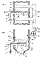
- Figure I is a schematic view of the device seen in vertical section. It is understood that the orientation of the fluidizing gas distribution orifices can be totally different; the vertical exhaust having been retained only for the clarity of the drawing.
- the device according to the invention comprises a fuel distribution ramp 5 arranged in the axis of the tube 2 for distributing the fluidizing gas. Fuel is released by the injectors 9 in the axis of the orifices 8 through which the fluidizing gas is released into the bed 4 which it sets in motion in the enclosure 1.
- a Venturi profile 12 or secondary distribution tubes 13 can be used optionally to improve distribution.
- a simple embodiment of the invention designed for gas preheating and the use of solid fuel in service can be carried out according to Figures I and II.
- Metal tubes 2 and 20 passing through the wall of the furnace I are positioned in the bed 4. These are plugged at one end and pierced with a number of holes 8 through which the fluidizing gas is released into the bed.
- In the axis of one or more of these tubes are mounted fuel distribution rails 5.
- Injectors 9 release the fuel gas in the axis of the orifices 8.
- Igniters 22 placed above the bed allow the fuel to ignite. These can be deleted in this example after use.
- the oxidizer is supplied by supplying 15 with ambient air.
- a valve 7 controls the arrival of the fuel.
- a temperature sensor 10 monitors the temperature at the fuel rail 5 and prevents the valve 7 from opening above a fixed temperature threshold.
- a probe 6 also prohibits the opening of the valve 7 until a stream of air 15 has been created in the tube 2.
- the tubes 20 not provided with a heating ramp are connected to a pipe 21 by which the additional fluidizing gas l6 is sent to the bed.
- the solid fuel 34 is loaded into a hopper 30. Its flow rate is set at 33.
- One or more hammer mills 31 projects it into the hearth at 35 after having made it tra pour the grid 32.
- the profile of the hammers and the speed of rotation of the grinder are such that the air current thus created is sufficient to prevent any flame rise while not disturbing the combustion inside the hearth.
- a lock valve 25 or any other device makes it possible to extract the excess bed and ash so as to maintain an optimum level of operation.
- the flow rate of the cold fluidizing gas is sufficient to keep the ramp 5 at a temperature low enough to use it as the sole fuel distributor.
- the device, object of the invention can be used in all cases where combustion, pyrolysis or calcination is carried out in a fluidized bed, techniques common in the industry. Particularly interesting applications can be the realization of furnaces or fluidized bed heating installations using various solid fuels or having to run on gas. The use of the process for starting a fluidized bed furnace is particularly efficient.
Landscapes
- Engineering & Computer Science (AREA)
- Chemical & Material Sciences (AREA)
- Mechanical Engineering (AREA)
- General Engineering & Computer Science (AREA)
- Combustion & Propulsion (AREA)
- Dispersion Chemistry (AREA)
- Organic Chemistry (AREA)
- Chemical Kinetics & Catalysis (AREA)
- Crucibles And Fluidized-Bed Furnaces (AREA)
- Fluidized-Bed Combustion And Resonant Combustion (AREA)
- Devices And Processes Conducted In The Presence Of Fluids And Solid Particles (AREA)
Applications Claiming Priority (2)
| Application Number | Priority Date | Filing Date | Title |
|---|---|---|---|
| FR8108523A FR2505027A1 (fr) | 1981-04-29 | 1981-04-29 | Procede de demarrage, de prechauffage ou de chauffage d'un ensemble de combustion a lit fluidise et appareil s'y rapportant |
| FR8108523 | 1981-04-29 |
Publications (1)
| Publication Number | Publication Date |
|---|---|
| EP0064911A1 true EP0064911A1 (fr) | 1982-11-17 |
Family
ID=9257894
Family Applications (1)
| Application Number | Title | Priority Date | Filing Date |
|---|---|---|---|
| EP82400763A Withdrawn EP0064911A1 (fr) | 1981-04-29 | 1982-04-28 | Procédé de démarrage, de préchauffage ou de chauffage d'un ensemble de combustion à lit fluidisé et appareillage s'y rapportant |
Country Status (2)
| Country | Link |
|---|---|
| EP (1) | EP0064911A1 (enExample) |
| FR (1) | FR2505027A1 (enExample) |
Cited By (6)
| Publication number | Priority date | Publication date | Assignee | Title |
|---|---|---|---|---|
| AT378591B (de) * | 1983-03-11 | 1985-08-26 | Waagner Biro Ag | Wirbelschichtfeuerungsanlage fuer brennstoffe unterschiedlicher qualitaet mit unverbrennbarem fremdkoerpereinschluss |
| WO1991004444A1 (en) * | 1989-09-22 | 1991-04-04 | Abb Stal Ab | A method and a device for preheating a fluidized bed |
| DE4128552A1 (de) * | 1990-08-29 | 1992-04-23 | Hoelter Heinz | Vorrichtung zur zufuhr von luft in eine wirbelschichtfeuerung |
| WO2000043713A1 (en) * | 1999-01-21 | 2000-07-27 | Kvaerner Pulping Oy | Method in connection with a pipe grate for fluidized bed boiler and a pipe grate |
| EP1320411A4 (en) * | 2000-09-18 | 2004-04-28 | Procedyne Corp | FLUID BED GAS DISTRIBUTION SYSTEM FOR OPERATION AT INCREASED TEMPERATURES |
| CN110274986A (zh) * | 2019-06-27 | 2019-09-24 | 河南省科学院能源研究所有限公司 | 一种生物质燃气与煤耦合燃烧的实验方法及装置 |
Citations (5)
| Publication number | Priority date | Publication date | Assignee | Title |
|---|---|---|---|---|
| GB1417986A (en) * | 1972-04-20 | 1975-12-17 | British Petroleum Co | Distributor plate |
| DE2612198A1 (de) * | 1976-03-23 | 1977-09-29 | Georg Raschka Fa Dipl Ing | Verfahren und vorrichtung zum eintragen pastoesen oder klumpigen gutes in einen wirbelschichtofen, insbesondere zum eintragen von klaerschlamm |
| DE2644146A1 (de) * | 1976-09-30 | 1978-04-06 | Metallgesellschaft Ag | Verfahren und vorrichtung zur direkten beheizung eines wirbelschichtofens |
| FR2446440A1 (fr) * | 1979-01-10 | 1980-08-08 | Energy Equip | Dispositif d'alimentation d'un gaz fluidisant a un lit fluidise, dans un systeme de combustion |
| WO1981002057A1 (en) * | 1980-01-16 | 1981-07-23 | Pyrecon Pty Ltd | Spouted and fluidised bed combustors |
Family Cites Families (2)
| Publication number | Priority date | Publication date | Assignee | Title |
|---|---|---|---|---|
| DE1758244B1 (de) * | 1968-04-27 | 1971-05-19 | Metallgesellschaft Ag | Vorrichtung zur gleichmaessigen dosierten zufuhr von brennstoffund luft in eine wirbelschicht |
| GB2053018B (en) * | 1979-06-30 | 1983-07-20 | British Petroleum Co | Combustor |
-
1981
- 1981-04-29 FR FR8108523A patent/FR2505027A1/fr active Granted
-
1982
- 1982-04-28 EP EP82400763A patent/EP0064911A1/fr not_active Withdrawn
Patent Citations (5)
| Publication number | Priority date | Publication date | Assignee | Title |
|---|---|---|---|---|
| GB1417986A (en) * | 1972-04-20 | 1975-12-17 | British Petroleum Co | Distributor plate |
| DE2612198A1 (de) * | 1976-03-23 | 1977-09-29 | Georg Raschka Fa Dipl Ing | Verfahren und vorrichtung zum eintragen pastoesen oder klumpigen gutes in einen wirbelschichtofen, insbesondere zum eintragen von klaerschlamm |
| DE2644146A1 (de) * | 1976-09-30 | 1978-04-06 | Metallgesellschaft Ag | Verfahren und vorrichtung zur direkten beheizung eines wirbelschichtofens |
| FR2446440A1 (fr) * | 1979-01-10 | 1980-08-08 | Energy Equip | Dispositif d'alimentation d'un gaz fluidisant a un lit fluidise, dans un systeme de combustion |
| WO1981002057A1 (en) * | 1980-01-16 | 1981-07-23 | Pyrecon Pty Ltd | Spouted and fluidised bed combustors |
Cited By (8)
| Publication number | Priority date | Publication date | Assignee | Title |
|---|---|---|---|---|
| AT378591B (de) * | 1983-03-11 | 1985-08-26 | Waagner Biro Ag | Wirbelschichtfeuerungsanlage fuer brennstoffe unterschiedlicher qualitaet mit unverbrennbarem fremdkoerpereinschluss |
| WO1991004444A1 (en) * | 1989-09-22 | 1991-04-04 | Abb Stal Ab | A method and a device for preheating a fluidized bed |
| DE4128552A1 (de) * | 1990-08-29 | 1992-04-23 | Hoelter Heinz | Vorrichtung zur zufuhr von luft in eine wirbelschichtfeuerung |
| WO2000043713A1 (en) * | 1999-01-21 | 2000-07-27 | Kvaerner Pulping Oy | Method in connection with a pipe grate for fluidized bed boiler and a pipe grate |
| US6571746B1 (en) | 1999-01-21 | 2003-06-03 | Kvaerner Pulping Oy | Method in connection with a pipe grate for fluidized bed boiler and a pipe grate |
| US6782848B2 (en) | 1999-01-21 | 2004-08-31 | Kvaerner Power Oy | Method in connection with a pipe grate for fluidized bed boiler and a pipe grate |
| EP1320411A4 (en) * | 2000-09-18 | 2004-04-28 | Procedyne Corp | FLUID BED GAS DISTRIBUTION SYSTEM FOR OPERATION AT INCREASED TEMPERATURES |
| CN110274986A (zh) * | 2019-06-27 | 2019-09-24 | 河南省科学院能源研究所有限公司 | 一种生物质燃气与煤耦合燃烧的实验方法及装置 |
Also Published As
| Publication number | Publication date |
|---|---|
| FR2505027A1 (fr) | 1982-11-05 |
| FR2505027B1 (enExample) | 1983-12-16 |
Similar Documents
| Publication | Publication Date | Title |
|---|---|---|
| US4023508A (en) | Apparatus to burn waste combustible polymers | |
| EP0566425A1 (en) | Apparatus for incinerating waste material | |
| FR2517042A1 (fr) | Appareil d'utilisation des gaz de fumees pour un four electrique | |
| EP1716365A1 (fr) | Dispositif et procede de destruction de dechets liquides, pulverulents ou gazeux par plasma inductif | |
| EP0064911A1 (fr) | Procédé de démarrage, de préchauffage ou de chauffage d'un ensemble de combustion à lit fluidisé et appareillage s'y rapportant | |
| FR2687765A1 (fr) | Procede et dispositif de controle de l'auto-combustion dans les installations de cremation. | |
| JPS62134414A (ja) | 半導体製造排ガスの燃焼方法及び同燃焼装置 | |
| US5257587A (en) | Method and apparatus for introducing and incinerating solid combustible waste in a rotary kiln | |
| JP3033015B2 (ja) | 半乾留ガス化焼却方法及び装置 | |
| EP1247046B1 (fr) | Methode et dispositif d'auto-combustion de dechets organiques graisseux comportant un foyer a chauffe tangentielle | |
| EP2956716A2 (fr) | Installation de production et de traitement de fumees | |
| EP0094890A1 (fr) | Chaudière à combustible solide du type à tube foyer rayonnant, procédé de transformation d'une chaudière et moyens pour sa mise en oeuvre | |
| EP0192502B1 (fr) | Procédé de préchauffage d'un gaz comburant par des gaz de combustion et dispositif de préchauffage associé à un brûleur comportant application de ce procédé | |
| FR2514864A1 (fr) | Tete de bruleur pour la combustion de combustibles solides | |
| EP1395776A1 (fr) | Generateur thermique et procede de combustion permettant de limiter les emissions d'oxydes d'azote par recombustion des fumees | |
| US4050387A (en) | Fluid industrial waste incinerator and its method of operation | |
| WO2011157913A1 (fr) | Installation de production et de traitement de fumees | |
| EP0970326A1 (fr) | Incinerateur et procede d'incineration de dechets liquides, pateux et solides | |
| US3658016A (en) | Incinerator | |
| EP0568202A1 (en) | Method of incinerating waste in a rotary kiln plant, and plant therefor | |
| EP3568636B1 (en) | Post-combustion device and method | |
| KR0136736B1 (ko) | 피소각물의 투입장치 및 그것을 사용한 소각로 | |
| EP0232658A1 (fr) | Procédé et dispositif de réaction exothermique entre des gaz | |
| FR2505028A1 (fr) | Incinerateur polyvalent de dechet solides et liquides | |
| JPH10185137A (ja) | 半乾留ガス化焼却方法及び装置 |
Legal Events
| Date | Code | Title | Description |
|---|---|---|---|
| PUAI | Public reference made under article 153(3) epc to a published international application that has entered the european phase |
Free format text: ORIGINAL CODE: 0009012 |
|
| AK | Designated contracting states |
Designated state(s): AT BE CH DE GB IT LU NL SE |
|
| 17P | Request for examination filed |
Effective date: 19830520 |
|
| STAA | Information on the status of an ep patent application or granted ep patent |
Free format text: STATUS: THE APPLICATION IS DEEMED TO BE WITHDRAWN |
|
| 18D | Application deemed to be withdrawn |
Effective date: 19840801 |