EP0064699A1 - A separable slide fastener - Google Patents
A separable slide fastener Download PDFInfo
- Publication number
- EP0064699A1 EP0064699A1 EP82103720A EP82103720A EP0064699A1 EP 0064699 A1 EP0064699 A1 EP 0064699A1 EP 82103720 A EP82103720 A EP 82103720A EP 82103720 A EP82103720 A EP 82103720A EP 0064699 A1 EP0064699 A1 EP 0064699A1
- Authority
- EP
- European Patent Office
- Prior art keywords
- separable
- endmost
- pin
- fused
- pair
- Prior art date
- Legal status (The legal status is an assumption and is not a legal conclusion. Google has not performed a legal analysis and makes no representation as to the accuracy of the status listed.)
- Granted
Links
- 230000008878 coupling Effects 0.000 claims abstract description 47
- 238000010168 coupling process Methods 0.000 claims abstract description 47
- 238000005859 coupling reaction Methods 0.000 claims abstract description 47
- 229920003002 synthetic resin Polymers 0.000 claims abstract description 7
- 239000000057 synthetic resin Substances 0.000 claims abstract description 7
- 229920001169 thermoplastic Polymers 0.000 claims abstract description 7
- 239000004416 thermosoftening plastic Substances 0.000 claims abstract description 7
- 238000009958 sewing Methods 0.000 claims description 13
- 238000006073 displacement reaction Methods 0.000 abstract description 2
- 230000003014 reinforcing effect Effects 0.000 description 9
- 239000004677 Nylon Substances 0.000 description 1
- 238000010438 heat treatment Methods 0.000 description 1
- 229920001778 nylon Polymers 0.000 description 1
- 238000005192 partition Methods 0.000 description 1
- 229920000728 polyester Polymers 0.000 description 1
- 238000003466 welding Methods 0.000 description 1
Images


Classifications
-
- A—HUMAN NECESSITIES
- A43—FOOTWEAR
- A43B—CHARACTERISTIC FEATURES OF FOOTWEAR; PARTS OF FOOTWEAR
- A43B13/00—Soles; Sole-and-heel integral units
- A43B13/14—Soles; Sole-and-heel integral units characterised by the constructive form
-
- A—HUMAN NECESSITIES
- A44—HABERDASHERY; JEWELLERY
- A44B—BUTTONS, PINS, BUCKLES, SLIDE FASTENERS, OR THE LIKE
- A44B19/00—Slide fasteners
- A44B19/24—Details
- A44B19/38—Means at the end of stringer by which the slider can be freed from one stringer, e.g. stringers can be completely separated from each other
-
- Y—GENERAL TAGGING OF NEW TECHNOLOGICAL DEVELOPMENTS; GENERAL TAGGING OF CROSS-SECTIONAL TECHNOLOGIES SPANNING OVER SEVERAL SECTIONS OF THE IPC; TECHNICAL SUBJECTS COVERED BY FORMER USPC CROSS-REFERENCE ART COLLECTIONS [XRACs] AND DIGESTS
- Y10—TECHNICAL SUBJECTS COVERED BY FORMER USPC
- Y10T—TECHNICAL SUBJECTS COVERED BY FORMER US CLASSIFICATION
- Y10T24/00—Buckles, buttons, clasps, etc.
- Y10T24/25—Zipper or required component thereof
- Y10T24/2518—Zipper or required component thereof having coiled or bent continuous wire interlocking surface
- Y10T24/2527—Attached by stitching
-
- Y—GENERAL TAGGING OF NEW TECHNOLOGICAL DEVELOPMENTS; GENERAL TAGGING OF CROSS-SECTIONAL TECHNOLOGIES SPANNING OVER SEVERAL SECTIONS OF THE IPC; TECHNICAL SUBJECTS COVERED BY FORMER USPC CROSS-REFERENCE ART COLLECTIONS [XRACs] AND DIGESTS
- Y10—TECHNICAL SUBJECTS COVERED BY FORMER USPC
- Y10T—TECHNICAL SUBJECTS COVERED BY FORMER US CLASSIFICATION
- Y10T24/00—Buckles, buttons, clasps, etc.
- Y10T24/25—Zipper or required component thereof
- Y10T24/2593—Zipper or required component thereof including complementary, aligning means attached to ends of interlocking surfaces
- Y10T24/2595—Zipper or required component thereof including complementary, aligning means attached to ends of interlocking surfaces having specific mounting connection or reinforcing structure at connection
Definitions
- the present invention relates to a slide fastener and more particularly to a separable type of slide fastener having a separable terminal assembly.
- the terminal assembly comprises a box and a box pin extending therefrom, which are mounted on one of the stringer tapes at a lower end thereof, and a separable pin mounted on the other stringer tape at a lower end thereof and engageable with the box, each pin having a pair of spaced upper and lower plates.
- connecting portions of the lowermost coupling elements are fused to the respec- the tive stringer tapes.
- / box pin and the separable pin are placed on the tape lower ends astride the respective inner longidudinal edges and extensions of the reinforcing core threads and the sewing stitches laid over the tape lower ends.
- the box and box pin and the separable pin are secured, by a clinching tool, to the respective tape lower ends with the top edges of the pins held in abutting engagement with legs of the lowermost coupling elements. Since the upper and lower plates of each pin have the same length, they as secured to the tape ends are arranged in superposed relation to one of the fused lowermost connecting portions.
- the present invention seeks to provide an improved separable slide fastener which will eliminate the above- noted difficulties of the prior art devices.
- the invention further seeks to provide a separable slide fastener wherein a slider is allowed to move smoothly toward and away from a separable terminal assembly.
- a separable slide fastener comprising a pair of stringer tapes each carrying on its one longitudinal edge a row of continuous coupling elements made of thermoplastic synthetic resin, each said coupling element having a coupling head, a pair of spaced legs extending from said coupling head in a common direction, and a connector extending from one of said legs to one leg of adjacent one coupling element, sewing stitches securing said rows of coupling elements to the respective stringer tapes, a separable terminal assembly comprising a box and a box pin extending therefrom, which are mounted on one of said stringer tapes at one end thereof, and a separable pin mounted on the other stringer tape at one end thereof and engageable with said box, said connectors of the endmost coupling elements located adjacent to said pins being fused with the respective stringer tapes, said pins each having a pair of opposite plates disposed one on each side of the respective stringer tapes, characterized in that one of said plates extends beyond the other plate to overlie each said
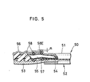
- a separable pin 50 of a conventional separable terminal assembly has a pair of flanged upper and lower plates 51,52 between which the lower end of a stringer tape 53witha. reinforcing film 54 disposed thereon, a core thread 55 and sewing stitches 56 are gripped.
- the plates 51,52 have the same length and are held in superposed relation to a fused connector 57 of the endmost one (58E) of a row of coiled coupling elements 58 sewn to the stringer tape 53. Due to stresses created during clinching operation of the separable pin 50, the sewing stitches 56, the core thread 55 and the reinforced tape end portion have been squeezed out from the separable pin 50.
- the endmost coupling element 58E is therefore displaced upwardly beyond the upper level of the succeeding elements 58 by a distance a toward adjacent one or the second lowermost coupling element.
- the displaced endmost coupling element 58E hinders smooth sliding movement of a slider (not shown) toward and away from the separable terminal assembly.
- a separable slide fastener 10 comprises a pair of stringer tapes 11,12 each carrying on and along its one longitudinal edge a row of coupling elements 13 in the form of a continuous filamentary coil made of a thermoplastic synthetic resin such as nylon, polyester or the like.
- Each row of coupling elements 13 is secured to the tape 11,12 by means of sewing stitches 14 with a reinforcing core thread or stuffer warp 15 extending longitudinally through the coiled coupling element row 13.
- Each of the coupling elements 13 has a coupling head 16, a pair of spaced upper and lower legs 17,18 (the lower leg being shown in Figure 4) extending from the coupling head 16 in a common direction, and a connector 19 extending from the lower leg 18 to the upper leg 17 of adjacent one of the coupling elements, the lower leg 18 lying on one or the upper surface of the stringer tape 11,12.
- a separable terminal assembly 20 is mounted on lower ends of the stringer tapes 11,12 and includes a box 21 and a box pin 22 extending therefrom, the box 2 1 and the box pin 22 being secured by clinching to the lower end of the stringer tape 11 along the longitudinal edge thereof, and a separable pin 23 secured by clinching to the lower end of the stringer tape 12 along the longitudinal edge thereof and engageable with the box 21.
- the separable terminal assembly 20 is located at a lower end of the-rows of coupling elements 13.
- the connectors 19a,19b of the endmost coupling elements E l ,E l located adjacent to the pins 22,23 are fused with the respective stringer tapes 11,12.
- a pair of reinforcing films 24,25 of thermoplastic synthetic resin is mounted on the upper surfaces of the stringer tapes 11,12, respectively, at the lower ends thereof, each of the films 24,25 overlapping one of the fused connectors 19a,19b as best shown in Figure 4.
- a slider S is slidably mounted on the coupling element rows 13,13 to take them into and out of interdigitating engagement with each other for closing and opening the separable slide fastener 10.
- the box 21 and the box pin 22 of the separable terminal assembly 20 are formed integrally with each other.
- the box 21 includes a pair of flanged upper and lower wings 26,27 joined by a partition wall 28 extending centrally longitudinally of the wings 26,27 to form a pair of longitudinal grooves 29,30, one 29 for receiving the separable pin 23, and the other 30 for receiving the longitudinal edge of the stringer tape 11, the reinforcing film 24, the core thread 15 and the sewing stitches 14 that are located at the lower end of the stringer tape 11.
- the box pin 22 extends from the upper end of the box 21 and has a pair of upper and lower plates 31,32 interconnected at one end by a sidewall 33 to define therebetween a longitudinal groove 34 which communicates with, and has substantially the same contour as, the groove 30 in the box 21 for the same purpose as the groove 30.
- the lower plate 32 and the sidewall 33 are cut off or notched at the respective top ends so that the upper plate 31 extends beyond the top ends of the lower plate 32 and the sidewall 33 by a distance slightly larger than the area of the fused endmost connector 19a.
- the upper plate 31 has at the other end a longitudinal flange 35 projecting therefrom toward the lower plate 32.
- the separable pin 23 is of generally C-shaped cross section and has a pair of upper and lower plates their 36,37 interconnected at one ends by a sidewall 38 to define therebetween a longitudinal groove 39 for receiving therein the longitudinal edge of the stringer tape 12, the reinforcing film 25, the core thread 15 and the sewing stitches 14 that are located at the lower end of the stringer tape 12.
- the upper and lower plates 36,37 have, at the respective other ends, a pair of longitudinal flanges 40,41, respectively extending toward one another.
- the sidewall 38 is cut off or notched at the top end thereof and the lower plate 37 is also cut off or notched at the top end so that the sidewall 38 extends beyond the top end of the lower plate 37, and the upper plate 36 extends beyond the top end of the lower plate 37 by a distance larger than the area of the fused endmost connector 19b.
- the sidewall 38 has a lateral projection 42 adjacent to the top end thereof for projecting into notched portion of the sidewall 33 of the box pin 22 to thereby hold the pins 22,23 in a proper position shown in Figures 1 and 3 when the separable pin 23 is received in the groove 29 in the box 20.
- the reinforcing films 24,25 of thermoplastic synthetic resin are placed on the respective stringer tapes 11,12 at the lower ends thereof and then are fused with the tapes 11,12, respectively, in the same manner as the endmost connectors 19a,19b for reinforcing the tape lower ends.
- the separable pin 23 is placed on the reinforced tape lower end astride the inner longitudinal edge thereof with extensions of the sewing stitches 14 and the core thread 15 received in the groove 39.
- the top edge 43 of the upper plate 36 is held substantially in abutting engagement with the upper leg 17 of the endmost coupling element E1with a loop of the sewing stitches interposed therebetween.
- the top edge of the lower plate 37 terminates short of the fused endmost connector 19b. Then, the upper and lower plates 36,37 of the separable pin 23 are pressed by a suitable clinching tool (not shown) to move toward with each other, thereby positively gripping the tape lower end between the respective flanges 40,41, as shown in Figures 3 and 4.
- the endmost coupling element E 1 is prevented from displacing in any direction, in particular, upwardly away from the fused connector 19b toward adjacent coupling element because of the lower plate 37 held out of underlying relation to the fused connector 19b. While being created stresses tending to squeeze the tape 12, the core thread 15, and the sewing stitches 14 out from the groove 39 in the pin 23, they are substantially of neglectable order and hence have no influence on the displacement of the endmost coupling element E 1 .
- the attachment of the box 21 and the box pin 22 to the tape lower end is accomplished in the same manner as the retainer pin 23.
- the slider S can move smoothly over the endmost coupling elements E 1 ,E 1 toward and away from the terminal assembly 20 to open and close the separable slider fastener 10.
Landscapes
- Slide Fasteners (AREA)
- Bag Frames (AREA)
- Purses, Travelling Bags, Baskets, Or Suitcases (AREA)
- Details Of Garments (AREA)
Abstract
Description
- The present invention relates to a slide fastener and more particularly to a separable type of slide fastener having a separable terminal assembly.
- There have been proposed a number of separable slide fasteners with a separable terminal assembly which is located at a lower end of a pair of rows of filamentary coiled or zigzag coupling elements of thermoplastic synthetic resin sewn to a pair of stringer tapes, respectively, along inner longitudinal edges thereof with a reinforcing core thread extending through each of the coupling element rows. The terminal assembly comprises a box and a box pin extending therefrom, which are mounted on one of the stringer tapes at a lower end thereof, and a separable pin mounted on the other stringer tape at a lower end thereof and engageable with the box, each pin having a pair of spaced upper and lower plates. For mounting the terminal assembly, connecting portions of the lowermost coupling elements are fused to the respec- the tive stringer tapes. Then,/box pin and the separable pin are placed on the tape lower ends astride the respective inner longidudinal edges and extensions of the reinforcing core threads and the sewing stitches laid over the tape lower ends. Thereafter, the box and box pin and the separable pin are secured, by a clinching tool, to the respective tape lower ends with the top edges of the pins held in abutting engagement with legs of the lowermost coupling elements. Since the upper and lower plates of each pin have the same length, they as secured to the tape ends are arranged in superposed relation to one of the fused lowermost connecting portions. With this arrangement, stresses are created as the upper and lower plates are pressed toward one another, which the stresses tend to squeeze the core threads, sewing stitches and the tape ends out from the pins, with the result that the lowermost coupling elements are displaced in a direction away from the fused connecting portions toward adjacent ones of the coupling elements. The displaced lowermost coupling elements hinder smooth movement of the slider, when a slider moves toward and away from the separable terminal assembly to open and close the fastener. In some instances, the slider is clogged at a position just before the separable terminal assembly. The starting movement of the slider in the fastener closing direction is also liable to become sluggish, sometimes even impossible.
- The present invention seeks to provide an improved separable slide fastener which will eliminate the above- noted difficulties of the prior art devices.
- The invention further seeks to provide a separable slide fastener wherein a slider is allowed to move smoothly toward and away from a separable terminal assembly.
- According to the invention, there is provided a separable slide fastener comprising a pair of stringer tapes each carrying on its one longitudinal edge a row of continuous coupling elements made of thermoplastic synthetic resin, each said coupling element having a coupling head, a pair of spaced legs extending from said coupling head in a common direction, and a connector extending from one of said legs to one leg of adjacent one coupling element, sewing stitches securing said rows of coupling elements to the respective stringer tapes, a separable terminal assembly comprising a box and a box pin extending therefrom, which are mounted on one of said stringer tapes at one end thereof, and a separable pin mounted on the other stringer tape at one end thereof and engageable with said box, said connectors of the endmost coupling elements located adjacent to said pins being fused with the respective stringer tapes, said pins each having a pair of opposite plates disposed one on each side of the respective stringer tapes, characterized in that one of said plates extends beyond the other plate to overlie each said fused endmost connector, said other plate terminating short of the fused endmost connector.
- Many other advantages, features and additional objects of the present invention will become manifest to those versed in the art upon making reference to the detailed description and the accompanying drawings in which a preferred embodiment incorporating the principles of the present invention is shown by way of illustrative example.
- Figure 1 is a fragmentary plan view of a separable slide fastener of the present invention;
- Figure 2 is an enlarged exploded perspective view of a separable bottom end stop of the separable slide fastener shown in Figure 1;
- Figure 3 is an enlarged plan view of essential parts of the slide fastener of Figure 1;
- Figure 4 is a cross-sectional view taken along the line IV - IV of Figure 3; and
- Figure 5 is a cross-sectional, partly broken away view similar to Figure 4, but showing a conventional arrangement.
- As shown in Figure5,a
separable pin 50 of a conventional separable terminal assembly has a pair of flanged upper andlower plates film 54 disposed thereon, acore thread 55 andsewing stitches 56 are gripped. Theplates fused connector 57 of the endmost one (58E) of a row of coiledcoupling elements 58 sewn to thestringer tape 53. Due to stresses created during clinching operation of theseparable pin 50, thesewing stitches 56, thecore thread 55 and the reinforced tape end portion have been squeezed out from theseparable pin 50. Theendmost coupling element 58E is therefore displaced upwardly beyond the upper level of the succeedingelements 58 by a distance a toward adjacent one or the second lowermost coupling element. The displacedendmost coupling element 58E hinders smooth sliding movement of a slider (not shown) toward and away from the separable terminal assembly. - The present invention will now be described with reference to Figures 1 through 4.
- As shown in Figure 1, a
separable slide fastener 10 comprises a pair ofstringer tapes coupling elements 13 in the form of a continuous filamentary coil made of a thermoplastic synthetic resin such as nylon, polyester or the like. Each row ofcoupling elements 13 is secured to thetape sewing stitches 14 with a reinforcing core thread orstuffer warp 15 extending longitudinally through the coiledcoupling element row 13. Each of thecoupling elements 13 has acoupling head 16, a pair of spaced upper andlower legs 17,18 (the lower leg being shown in Figure 4) extending from thecoupling head 16 in a common direction, and aconnector 19 extending from thelower leg 18 to theupper leg 17 of adjacent one of the coupling elements, thelower leg 18 lying on one or the upper surface of thestringer tape separable terminal assembly 20 is mounted on lower ends of thestringer tapes box 21 and abox pin 22 extending therefrom, the box 21 and thebox pin 22 being secured by clinching to the lower end of thestringer tape 11 along the longitudinal edge thereof, and aseparable pin 23 secured by clinching to the lower end of thestringer tape 12 along the longitudinal edge thereof and engageable with thebox 21. Theseparable terminal assembly 20 is located at a lower end of the-rows ofcoupling elements 13. Theconnectors pins respective stringer tapes films stringer tapes films fused connectors coupling element rows separable slide fastener 10. As shown in Figure 2, thebox 21 and thebox pin 22 of theseparable terminal assembly 20 are formed integrally with each other. Thebox 21 includes a pair of flanged upper andlower wings partition wall 28 extending centrally longitudinally of thewings longitudinal grooves separable pin 23, and the other 30 for receiving the longitudinal edge of thestringer tape 11, thereinforcing film 24, thecore thread 15 and thesewing stitches 14 that are located at the lower end of thestringer tape 11. Thebox pin 22 extends from the upper end of thebox 21 and has a pair of upper andlower plates sidewall 33 to define therebetween alongitudinal groove 34 which communicates with, and has substantially the same contour as, thegroove 30 in thebox 21 for the same purpose as thegroove 30. Thelower plate 32 and thesidewall 33 are cut off or notched at the respective top ends so that theupper plate 31 extends beyond the top ends of thelower plate 32 and thesidewall 33 by a distance slightly larger than the area of the fusedendmost connector 19a. Theupper plate 31 has at the other end alongitudinal flange 35 projecting therefrom toward thelower plate 32. - The
separable pin 23 is of generally C-shaped cross section and has a pair of upper and lower plates their 36,37 interconnected at one ends by asidewall 38 to define therebetween alongitudinal groove 39 for receiving therein the longitudinal edge of thestringer tape 12, the reinforcingfilm 25, thecore thread 15 and thesewing stitches 14 that are located at the lower end of thestringer tape 12. The upper andlower plates longitudinal flanges sidewall 38 is cut off or notched at the top end thereof and thelower plate 37 is also cut off or notched at the top end so that thesidewall 38 extends beyond the top end of thelower plate 37, and theupper plate 36 extends beyond the top end of thelower plate 37 by a distance larger than the area of the fusedendmost connector 19b. Thesidewall 38 has alateral projection 42 adjacent to the top end thereof for projecting into notched portion of thesidewall 33 of thebox pin 22 to thereby hold thepins separable pin 23 is received in thegroove 29 in thebox 20. - Prior to the attachment of the
separable terminal assembly 20 to the lower ends of thestringer tapes stringer tapes stringer tapes sewing stitches connectors stringer tapes reinforcing films respective stringer tapes tapes endmost connectors - The
separable pin 23 is placed on the reinforced tape lower end astride the inner longitudinal edge thereof with extensions of thesewing stitches 14 and thecore thread 15 received in thegroove 39. In this instance, thetop edge 43 of theupper plate 36 is held substantially in abutting engagement with theupper leg 17 of the endmost coupling element E1with a loop of the sewing stitches interposed therebetween. On the other hand, the top edge of thelower plate 37 terminates short of the fusedendmost connector 19b. Then, the upper andlower plates separable pin 23 are pressed by a suitable clinching tool (not shown) to move toward with each other, thereby positively gripping the tape lower end between therespective flanges fused connector 19b toward adjacent coupling element because of thelower plate 37 held out of underlying relation to thefused connector 19b. While being created stresses tending to squeeze thetape 12, thecore thread 15, and thesewing stitches 14 out from thegroove 39 in thepin 23, they are substantially of neglectable order and hence have no influence on the displacement of the endmost coupling element E1. - The attachment of the
box 21 and thebox pin 22 to the tape lower end is accomplished in the same manner as theretainer pin 23. The slider S can move smoothly over the endmost coupling elements E1,E1 toward and away from theterminal assembly 20 to open and close theseparable slider fastener 10.
Claims (4)
Applications Claiming Priority (2)
| Application Number | Priority Date | Filing Date | Title |
|---|---|---|---|
| JP1981065137U JPS6239710Y2 (en) | 1981-05-07 | 1981-05-07 | |
| JP65137/81U | 1981-05-07 |
Publications (2)
| Publication Number | Publication Date |
|---|---|
| EP0064699A1 true EP0064699A1 (en) | 1982-11-17 |
| EP0064699B1 EP0064699B1 (en) | 1984-11-07 |
Family
ID=13278189
Family Applications (1)
| Application Number | Title | Priority Date | Filing Date |
|---|---|---|---|
| EP82103720A Expired EP0064699B1 (en) | 1981-05-07 | 1982-04-30 | A separable slide fastener |
Country Status (13)
| Country | Link |
|---|---|
| US (1) | US4414718A (en) |
| EP (1) | EP0064699B1 (en) |
| JP (1) | JPS6239710Y2 (en) |
| KR (1) | KR840001749Y1 (en) |
| AU (1) | AU533762B2 (en) |
| BR (1) | BR8202649A (en) |
| CA (1) | CA1179483A (en) |
| DE (2) | DE64699T1 (en) |
| ES (1) | ES264955Y (en) |
| GB (1) | GB2098270B (en) |
| HK (1) | HK63988A (en) |
| MY (1) | MY8700406A (en) |
| SG (1) | SG5887G (en) |
Cited By (2)
| Publication number | Priority date | Publication date | Assignee | Title |
|---|---|---|---|---|
| EP0104650A1 (en) * | 1982-09-27 | 1984-04-04 | Yoshida Kogyo K.K. | Improvement of or relating to slide fastener with a separator attached thereto |
| EP0107113A1 (en) * | 1982-09-30 | 1984-05-02 | Yoshida Kogyo K.K. | Separable slide fastener |
Families Citing this family (7)
| Publication number | Priority date | Publication date | Assignee | Title |
|---|---|---|---|---|
| JPS59120906U (en) * | 1983-02-02 | 1984-08-15 | ワイケイケイ株式会社 | Slide fastener releasable fitting |
| JPS6029509U (en) * | 1983-08-03 | 1985-02-28 | ワイケイケイ株式会社 | Slide fastener releasable fitting |
| JPH02128702A (en) * | 1988-11-08 | 1990-05-17 | Yoshida Kogyo Kk <Ykk> | Slide fastener with opening and fitting device |
| JPH06245806A (en) * | 1993-02-26 | 1994-09-06 | Yoshida Kogyo Kk <Ykk> | Opening/closing piece mounting and forming method of hidden slide fastener |
| JP2936148B2 (en) * | 1993-06-18 | 1999-08-23 | ワイケイケイ株式会社 | Hidden slide fastener separable bottom stop |
| JP3513522B2 (en) * | 1996-11-29 | 2004-03-31 | Ykk株式会社 | Release type slide fastener |
| TWI475968B (en) * | 2013-07-29 | 2015-03-11 | Fabrication and setting method of nylon double - layer tooth zipper |
Citations (11)
| Publication number | Priority date | Publication date | Assignee | Title |
|---|---|---|---|---|
| GB391611A (en) * | 1932-05-05 | 1933-05-04 | G E Prentice Mfg Co | Improvements in or relating to sliding-clasp fasteners |
| US2172213A (en) * | 1936-02-29 | 1939-09-05 | Whitehall Patents Corp | End stop for separable fasteners |
| US2526802A (en) * | 1948-11-26 | 1950-10-24 | Nat Fastener Corp | Slide fastener stop blank |
| US2640255A (en) * | 1946-08-15 | 1953-06-02 | North & Judd Mfg Co | Separating end fitting for slide fasteners |
| US2834084A (en) * | 1951-09-27 | 1958-05-13 | Louis H Morin | Separable fasteners |
| US3224061A (en) * | 1964-09-17 | 1965-12-21 | Scovill Manufacturing Co | Terminal member for plastic filament zippers |
| GB1030779A (en) * | 1964-02-13 | 1966-05-25 | Scovill Manufacturing Co | Improvements in or relating to sliding clasp fasteners |
| GB1184906A (en) * | 1966-04-13 | 1970-03-18 | Yoshida Kogyo Kk | Improvements in and relating to Sliding Clasp Fasteners |
| DE2242978A1 (en) * | 1972-09-01 | 1974-03-07 | Opti Holding Ag | ZIPPER WITH DIVISIBILITY DEVICE AND METHOD FOR ATTACHING THE COMPONENTS OF A DIVISIBLE DEVICE TO SUCH ZIPPER |
| DE2431924A1 (en) * | 1974-07-03 | 1976-01-22 | Opti Holding Ag | Open-ended slide fastener with anchored plastics links - has end links welded to tape for gapless engagement |
| FR2359584A1 (en) * | 1976-07-27 | 1978-02-24 | Yoshida Kogyo Kk | PROCEDURE FOR FIXING A LOWER STOPPER SEPARABLE FROM A PAIR OF TAPES OF A ZIPPER |
Family Cites Families (3)
| Publication number | Priority date | Publication date | Assignee | Title |
|---|---|---|---|---|
| US3046627A (en) * | 1960-05-09 | 1962-07-31 | Louis H Morin | Separator for invisible separable fastener stringers |
| US3333305A (en) * | 1965-11-01 | 1967-08-01 | Scovill Manufacturing Co | Terminal portions of plastic filament zippers |
| GB1174218A (en) * | 1967-05-18 | 1969-12-17 | Lysta As | Improvements in or relating to Separable Sliding Clasp Fasteners |
-
1981
- 1981-05-07 JP JP1981065137U patent/JPS6239710Y2/ja not_active Expired
-
1982
- 1982-04-22 GB GB8211640A patent/GB2098270B/en not_active Expired
- 1982-04-23 AU AU82961/82A patent/AU533762B2/en not_active Ceased
- 1982-04-30 DE DE198282103720T patent/DE64699T1/en active Pending
- 1982-04-30 DE DE8282103720T patent/DE3261183D1/en not_active Expired
- 1982-04-30 EP EP82103720A patent/EP0064699B1/en not_active Expired
- 1982-05-03 US US06/374,318 patent/US4414718A/en not_active Expired - Fee Related
- 1982-05-03 KR KR2019820003454U patent/KR840001749Y1/en active
- 1982-05-05 ES ES1982264955U patent/ES264955Y/en not_active Expired
- 1982-05-06 CA CA000402401A patent/CA1179483A/en not_active Expired
- 1982-05-06 BR BR8202649A patent/BR8202649A/en not_active IP Right Cessation
-
1987
- 1987-01-21 SG SG58/87A patent/SG5887G/en unknown
- 1987-12-31 MY MY1987406A patent/MY8700406A/en unknown
-
1988
- 1988-08-18 HK HK639/88A patent/HK63988A/en unknown
Patent Citations (11)
| Publication number | Priority date | Publication date | Assignee | Title |
|---|---|---|---|---|
| GB391611A (en) * | 1932-05-05 | 1933-05-04 | G E Prentice Mfg Co | Improvements in or relating to sliding-clasp fasteners |
| US2172213A (en) * | 1936-02-29 | 1939-09-05 | Whitehall Patents Corp | End stop for separable fasteners |
| US2640255A (en) * | 1946-08-15 | 1953-06-02 | North & Judd Mfg Co | Separating end fitting for slide fasteners |
| US2526802A (en) * | 1948-11-26 | 1950-10-24 | Nat Fastener Corp | Slide fastener stop blank |
| US2834084A (en) * | 1951-09-27 | 1958-05-13 | Louis H Morin | Separable fasteners |
| GB1030779A (en) * | 1964-02-13 | 1966-05-25 | Scovill Manufacturing Co | Improvements in or relating to sliding clasp fasteners |
| US3224061A (en) * | 1964-09-17 | 1965-12-21 | Scovill Manufacturing Co | Terminal member for plastic filament zippers |
| GB1184906A (en) * | 1966-04-13 | 1970-03-18 | Yoshida Kogyo Kk | Improvements in and relating to Sliding Clasp Fasteners |
| DE2242978A1 (en) * | 1972-09-01 | 1974-03-07 | Opti Holding Ag | ZIPPER WITH DIVISIBILITY DEVICE AND METHOD FOR ATTACHING THE COMPONENTS OF A DIVISIBLE DEVICE TO SUCH ZIPPER |
| DE2431924A1 (en) * | 1974-07-03 | 1976-01-22 | Opti Holding Ag | Open-ended slide fastener with anchored plastics links - has end links welded to tape for gapless engagement |
| FR2359584A1 (en) * | 1976-07-27 | 1978-02-24 | Yoshida Kogyo Kk | PROCEDURE FOR FIXING A LOWER STOPPER SEPARABLE FROM A PAIR OF TAPES OF A ZIPPER |
Cited By (2)
| Publication number | Priority date | Publication date | Assignee | Title |
|---|---|---|---|---|
| EP0104650A1 (en) * | 1982-09-27 | 1984-04-04 | Yoshida Kogyo K.K. | Improvement of or relating to slide fastener with a separator attached thereto |
| EP0107113A1 (en) * | 1982-09-30 | 1984-05-02 | Yoshida Kogyo K.K. | Separable slide fastener |
Also Published As
| Publication number | Publication date |
|---|---|
| KR840001749Y1 (en) | 1984-09-18 |
| EP0064699B1 (en) | 1984-11-07 |
| ES264955Y (en) | 1983-06-01 |
| DE3261183D1 (en) | 1984-12-13 |
| KR830003495U (en) | 1983-12-26 |
| JPS57178512U (en) | 1982-11-12 |
| JPS6239710Y2 (en) | 1987-10-09 |
| DE64699T1 (en) | 1983-05-26 |
| GB2098270B (en) | 1984-11-14 |
| AU533762B2 (en) | 1983-12-08 |
| ES264955U (en) | 1982-11-16 |
| SG5887G (en) | 1987-06-05 |
| MY8700406A (en) | 1987-12-31 |
| CA1179483A (en) | 1984-12-18 |
| AU8296182A (en) | 1982-11-18 |
| BR8202649A (en) | 1983-04-19 |
| HK63988A (en) | 1988-08-26 |
| US4414718A (en) | 1983-11-15 |
| GB2098270A (en) | 1982-11-17 |
Similar Documents
| Publication | Publication Date | Title |
|---|---|---|
| EP0097362B1 (en) | Slide fastener slider | |
| US4752992A (en) | Slide fastener with thermoplastic end stops | |
| EP0121116B1 (en) | Slide fastener stringer | |
| US4742603A (en) | Separable bottom-end-stop assembly for separable slide fastener | |
| US4223425A (en) | Slide fastener | |
| EP0124867B1 (en) | Slider for slide fasteners | |
| CA1282941C (en) | Fluid-tight slide fastener | |
| CA1121573A (en) | Separable slide fastener | |
| EP0064699B1 (en) | A separable slide fastener | |
| EP0368170B1 (en) | Separable slide fastener | |
| US4942648A (en) | Separable type water-resistant slide fasteners | |
| EP0021192A1 (en) | Separable slide fastener | |
| US4232431A (en) | Slide fastener | |
| US4429438A (en) | Slide fastener stringer | |
| EP0107113B1 (en) | Separable slide fastener | |
| US5913481A (en) | Separable slide fastener | |
| EP0064698B1 (en) | A slide fastener stringer and method and device for forming an end thereof | |
| EP0187302B1 (en) | Slide fastener with a pair of intermeshable top end stops | |
| EP0051219A1 (en) | Slide fastener with separable bottom end stop | |
| US4377022A (en) | Separable slide fastener | |
| US4439898A (en) | Slide fastener stringer | |
| EP0287972A1 (en) | Separable bottom end stop for slide fastener | |
| EP0041237A1 (en) | Bridge top stop for slide fasteners | |
| US4232432A (en) | Separable slide fastener |
Legal Events
| Date | Code | Title | Description |
|---|---|---|---|
| PUAI | Public reference made under article 153(3) epc to a published international application that has entered the european phase |
Free format text: ORIGINAL CODE: 0009012 |
|
| AK | Designated contracting states |
Designated state(s): BE DE FR IT NL |
|
| ITCL | It: translation for ep claims filed |
Representative=s name: JACOBACCI CASETTA & PERANI S.P.A. |
|
| TCNL | Nl: translation of patent claims filed | ||
| EL | Fr: translation of claims filed | ||
| 17P | Request for examination filed |
Effective date: 19830216 |
|
| DET | De: translation of patent claims | ||
| ITF | It: translation for a ep patent filed | ||
| GRAA | (expected) grant |
Free format text: ORIGINAL CODE: 0009210 |
|
| AK | Designated contracting states |
Designated state(s): BE DE FR IT NL |
|
| REF | Corresponds to: |
Ref document number: 3261183 Country of ref document: DE Date of ref document: 19841213 |
|
| ET | Fr: translation filed | ||
| PLBE | No opposition filed within time limit |
Free format text: ORIGINAL CODE: 0009261 |
|
| STAA | Information on the status of an ep patent application or granted ep patent |
Free format text: STATUS: NO OPPOSITION FILED WITHIN TIME LIMIT |
|
| 26N | No opposition filed | ||
| ITTA | It: last paid annual fee | ||
| PGFP | Annual fee paid to national office [announced via postgrant information from national office to epo] |
Ref country code: BE Payment date: 19940120 Year of fee payment: 13 |
|
| PGFP | Annual fee paid to national office [announced via postgrant information from national office to epo] |
Ref country code: FR Payment date: 19940121 Year of fee payment: 13 |
|
| PGFP | Annual fee paid to national office [announced via postgrant information from national office to epo] |
Ref country code: DE Payment date: 19940428 Year of fee payment: 13 |
|
| PGFP | Annual fee paid to national office [announced via postgrant information from national office to epo] |
Ref country code: NL Payment date: 19940430 Year of fee payment: 13 |
|
| PG25 | Lapsed in a contracting state [announced via postgrant information from national office to epo] |
Ref country code: BE Effective date: 19950430 |
|
| BERE | Be: lapsed |
Owner name: YOSHIDA KOGYO K.K. Effective date: 19950430 |
|
| PG25 | Lapsed in a contracting state [announced via postgrant information from national office to epo] |
Ref country code: NL Effective date: 19951101 |
|
| PG25 | Lapsed in a contracting state [announced via postgrant information from national office to epo] |
Ref country code: FR Effective date: 19951229 |
|
| NLV4 | Nl: lapsed or anulled due to non-payment of the annual fee |
Effective date: 19951101 |
|
| PG25 | Lapsed in a contracting state [announced via postgrant information from national office to epo] |
Ref country code: DE Effective date: 19960103 |
|
| REG | Reference to a national code |
Ref country code: FR Ref legal event code: ST |