EP0064444B1 - Eclairant pyrotechnique de grande puissance - Google Patents
Eclairant pyrotechnique de grande puissance Download PDFInfo
- Publication number
- EP0064444B1 EP0064444B1 EP82400716A EP82400716A EP0064444B1 EP 0064444 B1 EP0064444 B1 EP 0064444B1 EP 82400716 A EP82400716 A EP 82400716A EP 82400716 A EP82400716 A EP 82400716A EP 0064444 B1 EP0064444 B1 EP 0064444B1
- Authority
- EP
- European Patent Office
- Prior art keywords
- composition
- support structure
- flare
- pyrotechnic
- initiator
- Prior art date
- Legal status (The legal status is an assumption and is not a legal conclusion. Google has not performed a legal analysis and makes no representation as to the accuracy of the status listed.)
- Expired
Links
- 239000000203 mixture Substances 0.000 claims description 67
- 239000003999 initiator Substances 0.000 claims description 18
- 230000007423 decrease Effects 0.000 claims description 5
- 230000001934 delay Effects 0.000 claims description 5
- 238000012886 linear function Methods 0.000 claims description 3
- 238000005286 illumination Methods 0.000 description 4
- 230000003287 optical effect Effects 0.000 description 3
- 238000010276 construction Methods 0.000 description 1
- 230000007123 defense Effects 0.000 description 1
- 238000001514 detection method Methods 0.000 description 1
- 238000010586 diagram Methods 0.000 description 1
- 230000000694 effects Effects 0.000 description 1
- 230000005284 excitation Effects 0.000 description 1
- 239000003380 propellant Substances 0.000 description 1
Images
Classifications
-
- F—MECHANICAL ENGINEERING; LIGHTING; HEATING; WEAPONS; BLASTING
- F42—AMMUNITION; BLASTING
- F42B—EXPLOSIVE CHARGES, e.g. FOR BLASTING, FIREWORKS, AMMUNITION
- F42B4/00—Fireworks, i.e. pyrotechnic devices for amusement, display, illumination or signal purposes
- F42B4/26—Flares; Torches
Definitions
- the invention relates to pyrotechnic illuminants.
- the present invention provides a simple and effective solution to this problem.
- Such a combination is known in itself from FR-E 21 603, which further teaches mounting of the second delay pyrotechnic composition in an area located at the other end of the support structure.
- the pyrotechnic illuminant according to the invention is characterized in that the support structure comprises, from its end on the initiator side, radial through orifices distributed over its length, in that the second delay pyrotechnic composition is housed in said through orifices, and in that the length of these orifices decreases according to a substantially linear function of their distance from the initiator, the ratio of the decrease in the length of the orifices at a distance from the initiator and the ratio of the linear delays of the two delay pyrotechnic compositions being chosen so that the fire emerges practically at the same time outside the through orifices.
- the second delay pyrotechnic composition has a linear speed of fire propagation about 10 to 20 times lower than that of the first delay pyrotechnic composition.
- the through orifices are established in ribs integral with the hollow tubular core of the support structure.
- the internal cross section of the support structure gradually widens from the initiator.
- the thickness of the lining of the illuminating composition is substantially constant along the support structure.
- the distance between two adjacent through-holes, along the support structure be of the same order as the radial thickness of the lighting composition in line with a through-hole.
- the lining of the illuminating composition is established in a substantially isometric manner from each through orifice.
- the entire lighting composition is enclosed in a flexible envelope, such as a bag.
- the pyrotechnic light of the invention can be dropped, unloaded and / or propelled, for example from an aircraft. It will then serve to blind and / or damage the optical detection systems of an attacker.
- the illuminating composition operates in the infrared and / or in the visible, preferably both.
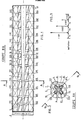
- the reference numeral 1 designates a support structure, of generally hollow tubular shape, which is advantageously made of rigid plastic. At one end of the support structure is arranged at least one initiator3; this can take many different embodiments, and is not illustrated in detail here.
- a first delay pyrotechnic composition In the internal tubular core 10 of the carrying structure 1 is placed a first delay pyrotechnic composition, generally designated by the reference numeral 2. This delay composition 2 comes into contact with the initiator 3, so that it can be lit by it.
- the internal tubular core 10 of the support structure is preferably of progressively increasing cross section as one moves away from the initiator 3.
- this tubular core 10 has a very elongated truncated cone shape.
- the support structure 1 is additionally provided with four ribs at right angles, designated by the reference 11 to 14. These ribs extend outward. From place to place, on the support structure, are formed in the ribs thereof, radial through holes; in Figure 2, we see four of the holes, namely the hole 113 in the rib 11, the hole 114 in the rib 12, the hole 115 in the rib 13, and finally the hole 116 in the rib
- the length of these through orifices 101 to 151 decreases according to a substantially linear function of their axial distance from the initiator 3; and, in the through holes, is placed a second delay pyrotechnic composition, designated by the general reference 4.
- the delay composition 2 is fast, while the delay composition 4 is slow.
- Figure 3 schematically illustrates this, with regard to the orifices 101 to 113.
- the distances between these orifices, taken on the axis of the support structure 1, are practically equal, and it can therefore be assumed that the delay in the pyrotechnic composition 2 s 'established at t o from one orifice to another.
- the orifice 101 will therefore receive the fire with a delay t o relative to the excitation of the initiator 3; and the light will emerge from this orifice 101 at the end of a delay t 101 ′ linked to the nature of the second delay pyrotechnic composition, as well as to the length of this orifice 101.
- the fire will emerge from orifice 101 at the end of a time equal to + tioi.
- the second delay pyrotechnic composition 4 has a linear speed of fire propagation about 10 to 20 times higher than that of the first delay pyrotechnic composition 2.
- This in practice allows a relatively easy construction taking into account the tolerances on delays. compositions and dimensions of the orifices, and this for a pyrotechnic illuminator of elongated structure.
- Another aspect of the invention contributes to the instantaneous high power of the lighting: it is made so that the thickness of the lining of the lighting composition is substantially constant along the support structure 1, and that on the other hand the linings of illuminating composition 5 are established in a substantially isometric manner from each through orifice.
- FIG. 2 this appears by the fact that the composition 5 is delimited by 4 arcs of a circle, which are each centered substantially at the exit point of the nearest through orifice.
- arcs of a circle a roughly equivalent structure can be provided, for example a square cross section, the vertices of which would be aligned with the axes of the through orifices in FIG. 2.
- the distance between two adjacent through holes, such as 101 and 105, taken along the support structure be of the same order as the radial thickness of the lighting composition 5 in line with a through hole.
- the fire is then simultaneously set in sufficient place in the lighting composition 5 for the triggering thereof to be almost instantaneous on the whole of its length.
- the entire lighting composition 5 is enclosed in a flexible envelope, such as a bag 6, which contributes to the good propagation of the information in the composition. illuminating, if that is still necessary.
- the pyrotechnic composition 2 which will contribute to the axial propagation of the fire in the support structure 1, it is possible to take a propagation speed of approximately 2,000 meters per second, this speed possibly going up to 8,000 meters per second. As previously indicated, the propagation speed of the other composition will be 10 to 20 times lower than that of the first, preferably 14 to 15 times lower than the latter.
- the lighting of the lighting pyrotechnic composition can then be obtained at the same time on the whole of the lighting, and this with a precision of the order of 10 ms.
Landscapes
- Engineering & Computer Science (AREA)
- General Engineering & Computer Science (AREA)
- Non-Portable Lighting Devices Or Systems Thereof (AREA)
- Physical Or Chemical Processes And Apparatus (AREA)
Applications Claiming Priority (2)
| Application Number | Priority Date | Filing Date | Title |
|---|---|---|---|
| FR8108106A FR2504670A1 (fr) | 1981-04-23 | 1981-04-23 | Eclairant pyrotechnique de grande puissance |
| FR8108106 | 1981-04-23 |
Publications (2)
| Publication Number | Publication Date |
|---|---|
| EP0064444A1 EP0064444A1 (fr) | 1982-11-10 |
| EP0064444B1 true EP0064444B1 (fr) | 1985-06-26 |
Family
ID=9257701
Family Applications (1)
| Application Number | Title | Priority Date | Filing Date |
|---|---|---|---|
| EP82400716A Expired EP0064444B1 (fr) | 1981-04-23 | 1982-04-21 | Eclairant pyrotechnique de grande puissance |
Country Status (7)
| Country | Link |
|---|---|
| US (1) | US4463679A (enExample) |
| EP (1) | EP0064444B1 (enExample) |
| DE (1) | DE3264405D1 (enExample) |
| DK (1) | DK151518C (enExample) |
| ES (1) | ES279685Y (enExample) |
| FR (1) | FR2504670A1 (enExample) |
| NO (1) | NO154936C (enExample) |
Families Citing this family (8)
| Publication number | Priority date | Publication date | Assignee | Title |
|---|---|---|---|---|
| FR2559255B1 (fr) * | 1984-02-03 | 1987-07-24 | Brandt Armements | Allumeur et cartouche d'allumage pour charge propulsive de projectile |
| DE3432291A1 (de) * | 1984-09-01 | 1986-03-13 | Rheinmetall GmbH, 4000 Düsseldorf | Treibladungsmodul |
| DE3515166A1 (de) * | 1985-04-26 | 1986-10-30 | Buck Chemisch-Technische Werke GmbH & Co, 7347 Bad Überkingen | Wurfkoerper zur darstellung eines infrarot-flaechenstrahlers |
| US5074216A (en) * | 1987-09-03 | 1991-12-24 | Loral Corporation | Infrared signature enhancement decoy |
| GB9120801D0 (en) * | 1991-10-01 | 1995-03-08 | Secr Defence | Propelled pyrotechnic decoy flare |
| US5565645A (en) * | 1995-04-24 | 1996-10-15 | Thiokol Corporation | High-intensity infrared decoy flare |
| US5866840A (en) * | 1997-09-17 | 1999-02-02 | Her Majesty The Queen In Right Of Canada, As Represented By The Minister Of National | Nozzles for pyrophoric IR decoy flares |
| US20170323240A1 (en) | 2016-05-06 | 2017-11-09 | General Electric Company | Computing system to control the use of physical state attainment with inspection |
Family Cites Families (5)
| Publication number | Priority date | Publication date | Assignee | Title |
|---|---|---|---|---|
| GB191517802A (en) * | 1915-12-20 | 1916-12-20 | Samuel Cleland Davidson | Improvements in or relating to Explosive Shells. |
| US1847268A (en) * | 1931-03-31 | 1932-03-01 | George J Schladt | Pyrotechnic device |
| US3494283A (en) * | 1966-12-27 | 1970-02-10 | Us Air Force | Cavity flare |
| US3670657A (en) * | 1970-04-30 | 1972-06-20 | Us Navy | Signal flare |
| US3970003A (en) * | 1974-10-16 | 1976-07-20 | Avco Corporation | Pyrophoric flare |
-
1981
- 1981-04-23 FR FR8108106A patent/FR2504670A1/fr active Granted
-
1982
- 1982-04-16 ES ES1982279685U patent/ES279685Y/es not_active Expired
- 1982-04-19 NO NO821256A patent/NO154936C/no unknown
- 1982-04-19 US US06/370,015 patent/US4463679A/en not_active Expired - Fee Related
- 1982-04-21 EP EP82400716A patent/EP0064444B1/fr not_active Expired
- 1982-04-21 DE DE8282400716T patent/DE3264405D1/de not_active Expired
- 1982-04-22 DK DK180382A patent/DK151518C/da not_active IP Right Cessation
Also Published As
| Publication number | Publication date |
|---|---|
| ES279685Y (es) | 1985-09-01 |
| US4463679A (en) | 1984-08-07 |
| NO821256L (no) | 1982-10-25 |
| EP0064444A1 (fr) | 1982-11-10 |
| ES279685U (es) | 1985-02-16 |
| DK151518B (da) | 1987-12-07 |
| NO154936B (no) | 1986-10-06 |
| DK151518C (da) | 1988-07-04 |
| DE3264405D1 (en) | 1985-08-01 |
| FR2504670A1 (fr) | 1982-10-29 |
| DK180382A (da) | 1982-10-24 |
| NO154936C (no) | 1987-01-14 |
| FR2504670B1 (enExample) | 1983-07-29 |
Similar Documents
| Publication | Publication Date | Title |
|---|---|---|
| EP3625624B1 (fr) | Dispositif de protection d'un capteur optique | |
| EP0064444B1 (fr) | Eclairant pyrotechnique de grande puissance | |
| EP0962741B1 (fr) | Dispositif de liaison provisoire et de séparation pyrotechinique de deux emsembles non metalliques | |
| EP0036818B1 (fr) | Dispositif porte-accessoires pour objectifs d'appareils de prises de vues photographiques et pare-soleil utilisable avec ce dispositif | |
| EP0519822B1 (fr) | Structure de suspension arrière du carter d'échappement d'un turboréacteur | |
| EP3620631A1 (fr) | Structure d'entrée d air d'une nacelle d aéronef | |
| EP0192556A1 (fr) | Carter de turbomachine associé à un dispositif pour ajuster le jeu entre aubes mobiles et carter | |
| WO1987007006A1 (fr) | Dispositif de separation pyrotechnique de deux elements | |
| EP0183617B1 (fr) | Dispositif de transmission, par couplage optique d'informations issues d'un volant de direction, à un organe solidaire d'un véhicule | |
| FR2522391A1 (fr) | Perfectionnements aux dispositifs emetteurs de lumiere pour vehicules automobiles | |
| EP3382270A1 (fr) | Guide de lumiere courbe propagateur de rayons lumineux | |
| EP0748999B1 (fr) | Tête militaire, notamment à charge génératrice de noyau | |
| FR2580377A1 (fr) | Feu de faible encombrement pour vehicule automobile | |
| EP1447581A1 (fr) | Dispositif de synchronisation pour boíte de vitesses mécaniques | |
| EP0117179B1 (fr) | Appareil de scellement d'éléments de fixation à chargeur | |
| FR2632722A1 (fr) | Dispositif destine a modifier la trajectoire d'un projectile par impulseurs pyrotechniques | |
| FR3022866A1 (fr) | Dispositif lumineux pour vehicule automobile a glace diffusante perfectionnee | |
| EP0307384B1 (fr) | Dispositif pour moduler un faisceau laser | |
| EP1127740B1 (fr) | Projecteur de véhicule automobile à masque et réflecteur | |
| EP1983495B1 (fr) | Détecteur de fumée avec dispositif adjacent à un réflecteur pour sélectionner un faisceau lumineux | |
| FR2667456A1 (fr) | Systeme de transmission de signaux de preference electrique entre deux pieces susceptibles de deplacement relatif a rotation. | |
| WO2020136039A1 (fr) | Dispositif de protection d'un capteur optique | |
| FR2500667A1 (fr) | Panneau lumineux, notamment pour la signalisation, l'affichage et la publicite | |
| FR2890643A1 (fr) | "engin volant supersonique" | |
| FR2888921A1 (fr) | Blindage reactif a effet de cisaillement |
Legal Events
| Date | Code | Title | Description |
|---|---|---|---|
| PUAI | Public reference made under article 153(3) epc to a published international application that has entered the european phase |
Free format text: ORIGINAL CODE: 0009012 |
|
| AK | Designated contracting states |
Designated state(s): BE DE GB IT NL |
|
| 17P | Request for examination filed |
Effective date: 19830113 |
|
| ITF | It: translation for a ep patent filed | ||
| GRAA | (expected) grant |
Free format text: ORIGINAL CODE: 0009210 |
|
| AK | Designated contracting states |
Designated state(s): BE DE GB IT NL |
|
| REF | Corresponds to: |
Ref document number: 3264405 Country of ref document: DE Date of ref document: 19850801 |
|
| BECN | Be: change of holder's name |
Effective date: 19850626 |
|
| RAP2 | Party data changed (patent owner data changed or rights of a patent transferred) |
Owner name: ETIENNE LACROIX - TOUS ARTIFICES SA |
|
| PLBE | No opposition filed within time limit |
Free format text: ORIGINAL CODE: 0009261 |
|
| STAA | Information on the status of an ep patent application or granted ep patent |
Free format text: STATUS: NO OPPOSITION FILED WITHIN TIME LIMIT |
|
| 26N | No opposition filed | ||
| NLT2 | Nl: modifications (of names), taken from the european patent patent bulletin |
Owner name: ETIENNE LACROIX - TOUS ARTIFICES S.A. TE MURET, FR |
|
| PGFP | Annual fee paid to national office [announced via postgrant information from national office to epo] |
Ref country code: GB Payment date: 19910415 Year of fee payment: 10 |
|
| ITTA | It: last paid annual fee | ||
| PGFP | Annual fee paid to national office [announced via postgrant information from national office to epo] |
Ref country code: NL Payment date: 19910430 Year of fee payment: 10 Ref country code: DE Payment date: 19910430 Year of fee payment: 10 |
|
| PGFP | Annual fee paid to national office [announced via postgrant information from national office to epo] |
Ref country code: BE Payment date: 19910514 Year of fee payment: 10 |
|
| PG25 | Lapsed in a contracting state [announced via postgrant information from national office to epo] |
Ref country code: GB Effective date: 19920421 |
|
| PG25 | Lapsed in a contracting state [announced via postgrant information from national office to epo] |
Ref country code: BE Effective date: 19920430 |
|
| BERE | Be: lapsed |
Owner name: ETIENNE LACROIX - TOUS ARTIFICES S.A. Effective date: 19920430 |
|
| PG25 | Lapsed in a contracting state [announced via postgrant information from national office to epo] |
Ref country code: NL Effective date: 19921101 |
|
| GBPC | Gb: european patent ceased through non-payment of renewal fee | ||
| NLV4 | Nl: lapsed or anulled due to non-payment of the annual fee | ||
| PG25 | Lapsed in a contracting state [announced via postgrant information from national office to epo] |
Ref country code: DE Effective date: 19930101 |