EP0064444B1 - Pyrotechnic flare having high luminous power - Google Patents
Pyrotechnic flare having high luminous power Download PDFInfo
- Publication number
- EP0064444B1 EP0064444B1 EP82400716A EP82400716A EP0064444B1 EP 0064444 B1 EP0064444 B1 EP 0064444B1 EP 82400716 A EP82400716 A EP 82400716A EP 82400716 A EP82400716 A EP 82400716A EP 0064444 B1 EP0064444 B1 EP 0064444B1
- Authority
- EP
- European Patent Office
- Prior art keywords
- composition
- support structure
- flare
- pyrotechnic
- initiator
- Prior art date
- Legal status (The legal status is an assumption and is not a legal conclusion. Google has not performed a legal analysis and makes no representation as to the accuracy of the status listed.)
- Expired
Links
- 239000000203 mixture Substances 0.000 claims description 67
- 239000003999 initiator Substances 0.000 claims description 18
- 230000007423 decrease Effects 0.000 claims description 5
- 230000001934 delay Effects 0.000 claims description 5
- 238000012886 linear function Methods 0.000 claims description 3
- 238000005286 illumination Methods 0.000 description 4
- 230000003287 optical effect Effects 0.000 description 3
- 238000010276 construction Methods 0.000 description 1
- 230000007123 defense Effects 0.000 description 1
- 238000001514 detection method Methods 0.000 description 1
- 238000010586 diagram Methods 0.000 description 1
- 230000000694 effects Effects 0.000 description 1
- 230000005284 excitation Effects 0.000 description 1
- 239000003380 propellant Substances 0.000 description 1
Images
Classifications
-
- F—MECHANICAL ENGINEERING; LIGHTING; HEATING; WEAPONS; BLASTING
- F42—AMMUNITION; BLASTING
- F42B—EXPLOSIVE CHARGES, e.g. FOR BLASTING, FIREWORKS, AMMUNITION
- F42B4/00—Fireworks, i.e. pyrotechnic devices for amusement, display, illumination or signal purposes
- F42B4/26—Flares; Torches
Definitions
- the invention relates to pyrotechnic illuminants.
- the present invention provides a simple and effective solution to this problem.
- Such a combination is known in itself from FR-E 21 603, which further teaches mounting of the second delay pyrotechnic composition in an area located at the other end of the support structure.
- the pyrotechnic illuminant according to the invention is characterized in that the support structure comprises, from its end on the initiator side, radial through orifices distributed over its length, in that the second delay pyrotechnic composition is housed in said through orifices, and in that the length of these orifices decreases according to a substantially linear function of their distance from the initiator, the ratio of the decrease in the length of the orifices at a distance from the initiator and the ratio of the linear delays of the two delay pyrotechnic compositions being chosen so that the fire emerges practically at the same time outside the through orifices.
- the second delay pyrotechnic composition has a linear speed of fire propagation about 10 to 20 times lower than that of the first delay pyrotechnic composition.
- the through orifices are established in ribs integral with the hollow tubular core of the support structure.
- the internal cross section of the support structure gradually widens from the initiator.
- the thickness of the lining of the illuminating composition is substantially constant along the support structure.
- the distance between two adjacent through-holes, along the support structure be of the same order as the radial thickness of the lighting composition in line with a through-hole.
- the lining of the illuminating composition is established in a substantially isometric manner from each through orifice.
- the entire lighting composition is enclosed in a flexible envelope, such as a bag.
- the pyrotechnic light of the invention can be dropped, unloaded and / or propelled, for example from an aircraft. It will then serve to blind and / or damage the optical detection systems of an attacker.
- the illuminating composition operates in the infrared and / or in the visible, preferably both.
- the reference numeral 1 designates a support structure, of generally hollow tubular shape, which is advantageously made of rigid plastic. At one end of the support structure is arranged at least one initiator3; this can take many different embodiments, and is not illustrated in detail here.
- a first delay pyrotechnic composition In the internal tubular core 10 of the carrying structure 1 is placed a first delay pyrotechnic composition, generally designated by the reference numeral 2. This delay composition 2 comes into contact with the initiator 3, so that it can be lit by it.
- the internal tubular core 10 of the support structure is preferably of progressively increasing cross section as one moves away from the initiator 3.
- this tubular core 10 has a very elongated truncated cone shape.
- the support structure 1 is additionally provided with four ribs at right angles, designated by the reference 11 to 14. These ribs extend outward. From place to place, on the support structure, are formed in the ribs thereof, radial through holes; in Figure 2, we see four of the holes, namely the hole 113 in the rib 11, the hole 114 in the rib 12, the hole 115 in the rib 13, and finally the hole 116 in the rib
- the length of these through orifices 101 to 151 decreases according to a substantially linear function of their axial distance from the initiator 3; and, in the through holes, is placed a second delay pyrotechnic composition, designated by the general reference 4.
- the delay composition 2 is fast, while the delay composition 4 is slow.
- Figure 3 schematically illustrates this, with regard to the orifices 101 to 113.
- the distances between these orifices, taken on the axis of the support structure 1, are practically equal, and it can therefore be assumed that the delay in the pyrotechnic composition 2 s 'established at t o from one orifice to another.
- the orifice 101 will therefore receive the fire with a delay t o relative to the excitation of the initiator 3; and the light will emerge from this orifice 101 at the end of a delay t 101 ′ linked to the nature of the second delay pyrotechnic composition, as well as to the length of this orifice 101.
- the fire will emerge from orifice 101 at the end of a time equal to + tioi.
- the second delay pyrotechnic composition 4 has a linear speed of fire propagation about 10 to 20 times higher than that of the first delay pyrotechnic composition 2.
- This in practice allows a relatively easy construction taking into account the tolerances on delays. compositions and dimensions of the orifices, and this for a pyrotechnic illuminator of elongated structure.
- Another aspect of the invention contributes to the instantaneous high power of the lighting: it is made so that the thickness of the lining of the lighting composition is substantially constant along the support structure 1, and that on the other hand the linings of illuminating composition 5 are established in a substantially isometric manner from each through orifice.
- FIG. 2 this appears by the fact that the composition 5 is delimited by 4 arcs of a circle, which are each centered substantially at the exit point of the nearest through orifice.
- arcs of a circle a roughly equivalent structure can be provided, for example a square cross section, the vertices of which would be aligned with the axes of the through orifices in FIG. 2.
- the distance between two adjacent through holes, such as 101 and 105, taken along the support structure be of the same order as the radial thickness of the lighting composition 5 in line with a through hole.
- the fire is then simultaneously set in sufficient place in the lighting composition 5 for the triggering thereof to be almost instantaneous on the whole of its length.
- the entire lighting composition 5 is enclosed in a flexible envelope, such as a bag 6, which contributes to the good propagation of the information in the composition. illuminating, if that is still necessary.
- the pyrotechnic composition 2 which will contribute to the axial propagation of the fire in the support structure 1, it is possible to take a propagation speed of approximately 2,000 meters per second, this speed possibly going up to 8,000 meters per second. As previously indicated, the propagation speed of the other composition will be 10 to 20 times lower than that of the first, preferably 14 to 15 times lower than the latter.
- the lighting of the lighting pyrotechnic composition can then be obtained at the same time on the whole of the lighting, and this with a precision of the order of 10 ms.
Landscapes
- Engineering & Computer Science (AREA)
- General Engineering & Computer Science (AREA)
- Non-Portable Lighting Devices Or Systems Thereof (AREA)
- Physical Or Chemical Processes And Apparatus (AREA)
Description
L'invention concerne les éclairants pyrotechniques.The invention relates to pyrotechnic illuminants.
En dehors de leurs applications classiques à l'illumination d'une zone obscure, on peut également envisager d'utiliser les éclairants pyrotechniques en défense, comme contre-mesure. Il s'agit alors littéralement d'aveugler un assaillant. Il vient immédiatement un problème : obtenir une grande puissance instantanée d'éclairement.Apart from their conventional applications for the illumination of a dark area, one can also consider using pyrotechnic lights in defense, as a countermeasure. It is literally a question of blinding an assailant. There is immediately a problem: to obtain a great instantaneous power of illumination.
La présente invention apporte une solution simple et efficace à ce problème.The present invention provides a simple and effective solution to this problem.
L'éclairant pyrotechnique proposé comporte, en combinaison :
- - une structure-support, de forme générale tubulaire creuse ;
- - une première composition pyrotechnique à retard placée dans l'âme tubulaire interne de la structure support ;
- - à l'une des extrémités de la structure-support, au moins un initiateur de la première composition pyrotechnique à retard ;
- - une seconde composition pyrotechnique à retard ;
- - une composition pyrotechnique éclairante gainant la structure support.
- - a support structure, of generally hollow tubular shape;
- - A first pyrotechnic composition with delay placed in the internal tubular core of the support structure;
- - At one end of the support structure, at least one initiator of the first delay pyrotechnic composition;
- - a second pyrotechnic composition with delay;
- - an illuminating pyrotechnic composition covering the support structure.
Une telle combinaison est connue en elle-même du fait de FR-E 21 603, qui enseigne en outre un montage de la seconde composition pyrotechnique à retard dans une zone localisée à l'autre des extrémités de la structure-support.Such a combination is known in itself from FR-E 21 603, which further teaches mounting of the second delay pyrotechnic composition in an area located at the other end of the support structure.
Un tel montage a pour effet que seule une zone également localisée de la composition pyrotechnique éclairante peut être soumise à l'influence directe de la seconde composition pyrotechnique à retard ; en d'autres termes, le feu se propage de la façon suivante à partir de l'initiateur, en pratique la charge propulsive :
- - de l'extrémité de la structure-support correspondant à l'initiateur à l'extrémité de celle-ci correspondant à la seconde composition pyrotechnique à retard, le long de la première composition pyrotechnique à retard puis de la deuxième composition pyrotechnique à retard,
- - de cette dernière à la zone de la composition pyrotechnique éclairante qui jouxte l'extrémité de la structure-support correspondant à la seconde composition pyrotechnique à retard,
- - puis le long de la charge pyrotechnique éclairante, de cette zone de celle-ci à sa zone jouxtant l'extrémité de la structure support correspondant à l'initiateur.
- from the end of the support structure corresponding to the initiator to the end of the latter corresponding to the second delay pyrotechnic composition, along the first delay pyrotechnic composition and then to the second delay pyrotechnic composition,
- - from the latter to the area of the illuminating pyrotechnic composition which adjoins the end of the support structure corresponding to the second delay pyrotechnic composition,
- - Then along the illuminating pyrotechnic charge, from this zone thereof to its zone adjoining the end of the support structure corresponding to the initiator.
Il en résulte un décalage, dans le temps, entre l'allumage des différentes zones de la composition pyrotechnique éclairante, ce qui procure un éclairement pendant la totalité de l'intervalle de temps séparant l'allumage des zones de cette composition correspondant respectivement à l'une et l'autre des extrémités de la structure-support, avec une médiocre puissance instantanée d'éclairement.This results in a time lag between the lighting of the different zones of the lighting pyrotechnic composition, which provides lighting during the entire time interval separating the lighting of the zones of this composition corresponding respectively to the 'one and the other of the ends of the support structure, with a poor instantaneous power of illumination.
Pour permettre d'obtenir une grande puissance instantanée d'éclairement, l'éclairant pyrotechnique selon l'invention se caractérise en ce que la structure-support comprend, à partir de son extrémité côté initiateur, des orifices traversants radiaux distribués sur sa longueur, en ce que la seconde composition pyrotechnique à retard est logée dans lesdits orifices traversants, et en ce que la longueur de ces orifices diminue selon une fonction sensiblement linéaire de leur éloignement vis-à-vis de l'initiateur, le rapport de la décroissance de la longueur des orifices à l'éloignement de l'initiateur et le rapport des retards linéiques des deux compositions pyrotechniques à retard étant choisis pour que le feu débouche pratiquement en même temps à l'extérieur des orifices traversants.To make it possible to obtain a large instantaneous power of illumination, the pyrotechnic illuminant according to the invention is characterized in that the support structure comprises, from its end on the initiator side, radial through orifices distributed over its length, in that the second delay pyrotechnic composition is housed in said through orifices, and in that the length of these orifices decreases according to a substantially linear function of their distance from the initiator, the ratio of the decrease in the length of the orifices at a distance from the initiator and the ratio of the linear delays of the two delay pyrotechnic compositions being chosen so that the fire emerges practically at the same time outside the through orifices.
De préférence, la seconde composition pyrotechnique à retard présente une vitesse linéique de propagation de feu environ 10 à 20 fois inférieure à celle de la première composition pyrotechnique à retard.Preferably, the second delay pyrotechnic composition has a linear speed of fire propagation about 10 to 20 times lower than that of the first delay pyrotechnic composition.
Dans un mode de réalisation particulier, les orifices traversants sont établis dans des nervures solidaires de l'âme tubulaire creuse de la structure-support.In a particular embodiment, the through orifices are established in ribs integral with the hollow tubular core of the support structure.
Avantageusement, les orifices traversants sont au nombre de 4, écartés de 90°, dans chaque section droite de la structure-support.Advantageously, there are 4 through holes, spaced 90 ° apart, in each cross section of the support structure.
Selon un autre aspect préférentiel de l'invention, la section droite interne de la structure-support s'élargit progressivement à partir de l'initiateur.According to another preferred aspect of the invention, the internal cross section of the support structure gradually widens from the initiator.
En pratique, l'épaisseur du garnissage de composition éclairante est sensiblement constante le long de la structure support.In practice, the thickness of the lining of the illuminating composition is substantially constant along the support structure.
Il est souhaitable, mais non impératif, que la distance entre deux orifices traversants adjacents, le long de la structure-support, soit du même ordre que l'épaisseur radiale de la composition éclairante au droit d'un orifice traversant.It is desirable, but not imperative, that the distance between two adjacent through-holes, along the support structure, be of the same order as the radial thickness of the lighting composition in line with a through-hole.
Selon un autre aspect préférentiel de l'invention, le garnissage de composition éclairante est établi de manière sensiblement isométrique à partir de chaque orifice traversant.According to another preferred aspect of the invention, the lining of the illuminating composition is established in a substantially isometric manner from each through orifice.
Avantageusement, l'ensemblé de la composition éclairante est enfermé dans une enveloppe souple, telle qu'un sac.Advantageously, the entire lighting composition is enclosed in a flexible envelope, such as a bag.
L'éclairant pyrotechnique de l'invention peut être largué, dépoté et/ou propulsé, par exemple à partir d'un aéronef. Il servira alors à aveugler et/ou léser les systèmes de détection optique d'un assaillant.The pyrotechnic light of the invention can be dropped, unloaded and / or propelled, for example from an aircraft. It will then serve to blind and / or damage the optical detection systems of an attacker.
La composition éclairante opère dans l'infrarouge et/ou dans le visible, de préférence les deux.The illuminating composition operates in the infrared and / or in the visible, preferably both.
D'autres caractéristiques et avantages de l'invention apparaîtront à la lecture de la description détaillée qui va suivre, faite en référence aux dessins annexés, donnés pour illustrer à titre d'exemple non limitatif un mode de réalisation préférentiel de l'invention, et sur lesquels :
- La Figure 1 est une vue en coupe axiale d'un éclairant pyrotechnique selon la présente invention ;
- La Figure 2 est une vue en coupe transversale de l'éclairant de la Figure 1, suivant la ligne de coupe A-A ; et
- La Figure 3 est un schéma destiné à illustrer le mode de fonctionnement de l'éclairement pyrotechnique selon l'invention.
- Figure 1 is an axial sectional view of a pyrotechnic illuminant according to the present invention;
- Figure 2 is a cross-sectional view the illuminant of Figure 1, along the line of section AA; and
- Figure 3 is a diagram intended to illustrate the operating mode of the pyrotechnic lighting according to the invention.
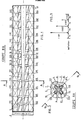
Sur la Figure 1, la référence numérique 1 désigne une structure-support, de forme générale tubulaire creuse, et qui est avantageusement réalisée en matière plastique rigide. A l'une des extrémités de la structure-support est disposé au moins un initiateur3 ; celui-ci peut revêtir de nombreuses formes de réalisation différentes, et n'est pas illustré en détail ici. Dans l'âme tubulaire interne 10 de la structure porteuse 1 est placée une première composition pyrotechnique à retard, désignée dans son ensemble par la référence numérique 2. Cette composition à retard 2 vient au contact de l'initiateur 3, de manière à pouvoir être allumée par celui-ci.In Figure 1, the
Ainsi que cela est illustré sur la Figure 1, l'âme tubulaire interne 10 de la structure-support est de préférence de section droite progressivement croissante au fur et à mesure que l'on s'éloigne de l'initiateur 3. Ici, cette âme tubulaire 10 possède une forme en tronc de cône très allongé. Comme le montre la Figure 2, la structure-support 1 est munie de surcroît de quatre nervures à angle droit, désigné par la référence 11 à 14. Ces nervures s'étendent vers l'extérieur. De place en place, sur la structure support, sont ménagés dans les nervures de celle-ci, des orifices traversants radiaux ; sur la Figure 2, on voit quatre des orifices, à savoir l'orifice 113 dans la nervure 11, l'orifice 114 dans la nervure 12, l'orifice 115 dans la nervure 13, et enfin l'orifice 116 dans la nervureAs illustrated in FIG. 1, the internal
14. Si l'on se réfère maintenant à la Figure 1, où n'apparaissent en coupe que les nervures 11 et 13, on voit que les orifices traversants s'étagent de manière régulièrement répartie tout le long de la structure support, en commençant par t'orifice 101, à l'orifice suivant non représenté, l'orifice 103, l'orifice suivant non représenté, et ainsi de suite pour la section droite suivante, et ce jusqu'à l'orifice 151, le tout dernier orifice n'étant également pas représenté.14. If we now refer to FIG. 1, where only the
Selon un aspect important de l'invention, la longueur de ces orifices traversants 101 à 151, diminue selon une fonction sensiblement linéaire de leur éloignement axial vis-à-vis de l'initiateur 3 ; et, dans les orifices traversants, est placée une seconde composition pyrotechnique à retard, désignée par la référence générale 4. En pratique, la composition à retard 2 est rapide, tandis que la composition à retard 4 est lente. On peut alors établir un premier rapport entre la décroissance de la longueur des orifices traversants tels que 101, etc. et leur éloignement de l'initiateur 3 ; on peut établir un rapport des retards linéiques procurés par les deux compositions pyrotechniques à retard 2 et 4, compte tenu à la fois de leurs caractéristiques propres et de leur disposition géométrique à l'intérieur de l'éclairant ; ces deux retards sont choisis pour que le feu débouche pratiquement en même temps à l'extérieur des orifices traversants.According to an important aspect of the invention, the length of these through
La Figure 3 illustre schématiquement cela, à propos des orifices 101 à 113. Les distances entre ces orifices, prises sur l'axe de la structure support 1, sont pratiquement égales, et on peut donc admettre que le retard de la composition pyrotechnique 2 s'établit à to d'un orifice à l'autre. L'orifice 101 va donc recevoir le feu avec un retard to par rapport à l'excitation de l'initiateur 3 ; et le feu débouchera en sortie de cet orifice 101 au terme d'un retard t101' lié à la nature de la seconde composition pyrotechnique à retard, ainsi qu'à la longueur de cet orifice 101. Le feu débouchera de l'orifice 101 au terme d'un temps égal to+tioi. Pour l'orifice 105, le feu arrivera par la composition 2 au terme d'un temps 2 - to, et l'orifice lui-même mettra un temps t105 pour propager le feu jusqu'à sa sortie. De même, pour l'orifice 109, on aura un temps global 3. to + t109; enfin, pour l'orifice 113, le feu débouchera au terme d'un temps 4 - to + t113.Figure 3 schematically illustrates this, with regard to the
Il suffit alors d'ajuster les différentes valeurs pour que soit satisfaite la relation suivante : t0 + t101 = 2 - t0 + t105 = 3 . t0 + t109 = 4 . t0 + t113.It then suffices to adjust the different values so that the following relation is satisfied: t 0 + t 101 = 2 - t 0 + t 105 = 3. t 0 + t 109 = 4. t 0 + t 113 .
Le feu qui débouche alors pratiquement en même temps de l'ensemble des orifices traversants va allumer une composition pyrotechnique éclairante 5 gainant la structure-support. Celle-ci se trouve allumée en même temps sur toute la longueur de l'éclairant, et l'on obtient alors une puissance instantanée considérable.The fire which then emerges practically at the same time from all of the through orifices will ignite an illuminating
De préférence, la seconde composition pyrotechnique à retard 4 présente une vitesse linéique de propagation de feu environ 10 à 20 fois supérieure à celle de la première composition pyrotechnique à retard 2. Cela permet en pratique une construction relativement aisée compte tenu des tolérances sur les retards des compositions et les dimensions des orifices, et ce pour un éclairant pyrotechnique de structure allongée.Preferably, the second delay
Un autre aspect de l'invention contribue à la haute puissance instantanée de l'éclairement : on fait en sorte que l'épaisseur du garnissage de composition éclairante soit sensiblement constant le long de la structure support 1, et que d'autre part les garnissages de composition éclairante 5 soient établis de manière sensiblement isométrique à partir de chaque orifice traversant. Sur la Figure 2, cela apparaît par le fait que la composition 5 est délimitée par 4 arcs de cercle, qui sont centrés chacun sensiblement au point de sortie de l'orifice traversant le plus proche. Bien entendu, au lieu d'arcs de cercle, on peut prévoir une structure à peu près équivalente, par exemple une section droite carrée, dont les sommets seraient alignés avec les axes des orifices traversants de la Figure 2.Another aspect of the invention contributes to the instantaneous high power of the lighting: it is made so that the thickness of the lining of the lighting composition is substantially constant along the
Pour la même raison, il est souhaitable que la distance entre deux orifices traversants adjacents, tels que 101 et 105, prise le long de la structure support, soit du même ordre que l'épaisseur radiale de la composition éclairante 5 au droit d'un orifice traversant. On met alors le feu simultanément en suffisamment d'endroit de la composition éclairante 5 pour que le déclenchement de celle-ci soit quasi instantané sur l'ensemble de sa longueur.For the same reason, it is desirable that the distance between two adjacent through holes, such as 101 and 105, taken along the support structure, be of the same order as the radial thickness of the
Enfin, selon un autre aspect de l'invention, il est utile que l'ensemble de la composition éclairante 5 soit enfermé dans une enveloppe souple, telle qu'un sac 6, qui contribue à la bonne propagation de l'information dans la composition éclairante, si cela est encore nécessaire.Finally, according to another aspect of the invention, it is useful for the
Pour la composition pyrotechnique 2, qui va contribuer à la propagation axiale du feu dans la structure support 1, on pourra prendre une vitesse de propagation d'environ 2 000 mètres par seconde, cette vitesse pouvant aller jusqu'à 8 000 mètres par seconde. Comme précédemment indiqué, la vitesse de propagation de l'autre composition sera de 10 à 20 fois inférieure à celle de la première, de préférence 14 à 15 fois inférieure à celle-ci. L'allumage de la composition pyrotechnique éclairante peut être alors obtenu en même temps sur l'ensemble de l'éclairant, et ceci avec une précision de l'ordre de 10 mrsecon- des. On peut alors obtenir une puissance de 100 mégawatts optiques, à la fois dans le domaine de l'infrarouge et dans le domaine de la lumière visible. Une telle puissance est de nature à aveugler temporairement sinon définitivement les détecteurs optiques ou infrarouges d'un dispositif assaillant.For the
Claims (10)
characterised in that the support structure has, from the end thereof on the side of the initiator, radial transverse openings (105-151) distributed over its length, in that the second pyrotechnic delaying composition (4) is located in the said transverse openings (101-151), and in that the length of these openings decreases as a substantially linear function of their distance from the initiator, the ratio of the reduction in length of the openings (101, etc.) to the distance from the initiator (3) and the ratio of the linear delays of the two pyrotechnic delaying compositions (2 and 4) being selected such that the light issues almost simultaneously out of the transverse openings.
Applications Claiming Priority (2)
| Application Number | Priority Date | Filing Date | Title |
|---|---|---|---|
| FR8108106 | 1981-04-23 | ||
| FR8108106A FR2504670A1 (en) | 1981-04-23 | 1981-04-23 | HIGH POWER PYROTECHNIC LIGHTING |
Publications (2)
| Publication Number | Publication Date |
|---|---|
| EP0064444A1 EP0064444A1 (en) | 1982-11-10 |
| EP0064444B1 true EP0064444B1 (en) | 1985-06-26 |
Family
ID=9257701
Family Applications (1)
| Application Number | Title | Priority Date | Filing Date |
|---|---|---|---|
| EP82400716A Expired EP0064444B1 (en) | 1981-04-23 | 1982-04-21 | Pyrotechnic flare having high luminous power |
Country Status (7)
| Country | Link |
|---|---|
| US (1) | US4463679A (en) |
| EP (1) | EP0064444B1 (en) |
| DE (1) | DE3264405D1 (en) |
| DK (1) | DK151518C (en) |
| ES (1) | ES279685Y (en) |
| FR (1) | FR2504670A1 (en) |
| NO (1) | NO154936C (en) |
Families Citing this family (8)
| Publication number | Priority date | Publication date | Assignee | Title |
|---|---|---|---|---|
| FR2559255B1 (en) * | 1984-02-03 | 1987-07-24 | Brandt Armements | IGNITER AND IGNITION CARTRIDGE FOR PROPULSIVE CHARGE OF PROJECTILE |
| DE3432291A1 (en) * | 1984-09-01 | 1986-03-13 | Rheinmetall GmbH, 4000 Düsseldorf | DRIVE CHARGE MODULE |
| DE3515166A1 (en) * | 1985-04-26 | 1986-10-30 | Buck Chemisch-Technische Werke GmbH & Co, 7347 Bad Überkingen | THROWING BODY FOR THE DISPLAY OF AN INFRARED SURFACE SPOTLIGHT |
| US5074216A (en) * | 1987-09-03 | 1991-12-24 | Loral Corporation | Infrared signature enhancement decoy |
| GB9120801D0 (en) * | 1991-10-01 | 1995-03-08 | Secr Defence | Propelled pyrotechnic decoy flare |
| US5565645A (en) * | 1995-04-24 | 1996-10-15 | Thiokol Corporation | High-intensity infrared decoy flare |
| US5866840A (en) * | 1997-09-17 | 1999-02-02 | Her Majesty The Queen In Right Of Canada, As Represented By The Minister Of National | Nozzles for pyrophoric IR decoy flares |
| US10318904B2 (en) | 2016-05-06 | 2019-06-11 | General Electric Company | Computing system to control the use of physical state attainment of assets to meet temporal performance criteria |
Family Cites Families (5)
| Publication number | Priority date | Publication date | Assignee | Title |
|---|---|---|---|---|
| GB191517802A (en) * | 1915-12-20 | 1916-12-20 | Samuel Cleland Davidson | Improvements in or relating to Explosive Shells. |
| US1847268A (en) * | 1931-03-31 | 1932-03-01 | George J Schladt | Pyrotechnic device |
| US3494283A (en) * | 1966-12-27 | 1970-02-10 | Us Air Force | Cavity flare |
| US3670657A (en) * | 1970-04-30 | 1972-06-20 | Us Navy | Signal flare |
| US3970003A (en) * | 1974-10-16 | 1976-07-20 | Avco Corporation | Pyrophoric flare |
-
1981
- 1981-04-23 FR FR8108106A patent/FR2504670A1/en active Granted
-
1982
- 1982-04-16 ES ES1982279685U patent/ES279685Y/en not_active Expired
- 1982-04-19 NO NO821256A patent/NO154936C/en unknown
- 1982-04-19 US US06/370,015 patent/US4463679A/en not_active Expired - Fee Related
- 1982-04-21 EP EP82400716A patent/EP0064444B1/en not_active Expired
- 1982-04-21 DE DE8282400716T patent/DE3264405D1/en not_active Expired
- 1982-04-22 DK DK180382A patent/DK151518C/en not_active IP Right Cessation
Also Published As
| Publication number | Publication date |
|---|---|
| DE3264405D1 (en) | 1985-08-01 |
| DK151518B (en) | 1987-12-07 |
| FR2504670A1 (en) | 1982-10-29 |
| NO154936B (en) | 1986-10-06 |
| NO154936C (en) | 1987-01-14 |
| FR2504670B1 (en) | 1983-07-29 |
| DK151518C (en) | 1988-07-04 |
| US4463679A (en) | 1984-08-07 |
| ES279685U (en) | 1985-02-16 |
| EP0064444A1 (en) | 1982-11-10 |
| NO821256L (en) | 1982-10-25 |
| ES279685Y (en) | 1985-09-01 |
| DK180382A (en) | 1982-10-24 |
Similar Documents
| Publication | Publication Date | Title |
|---|---|---|
| EP0064444B1 (en) | Pyrotechnic flare having high luminous power | |
| EP0587501B1 (en) | Signal light having an improved lateral visibility | |
| EP0036818B1 (en) | Accessory mount for a camera lens and lens shade usable with it | |
| EP0519822B1 (en) | Suspension structure for a turbo engine exhaust casing | |
| FR2667457A1 (en) | Improvements to devices for transmission of signals between two components capable of relative rotational movement | |
| EP0246958A1 (en) | Device for pyrotechnically separating two elements | |
| EP0183617B1 (en) | Optical-signal transmission from the steering wheel to other parts of a vehicle | |
| FR2522391A1 (en) | IMPROVEMENTS IN LIGHT-EMITTING DEVICES FOR MOTOR VEHICLES | |
| EP3382270A1 (en) | Curved light guide propagating light rays | |
| FR2386107A1 (en) | ROTARY SHUTTER FOR PERIODICALLY INTERRUPTING THERMAL RADIATION | |
| FR2580377A1 (en) | Compact light for motor vehicle | |
| EP2963336A2 (en) | Light device for a motor vehicle with improved diffusing lens | |
| EP0117179B1 (en) | Explosive-actuated fastening tool with magazine | |
| EP1746379A1 (en) | Reactive armour with improved efficiency | |
| FR2632722A1 (en) | DEVICE FOR MODIFYING THE TRACK OF A PROJECTILE BY PYROTECHNIC IMPULSE | |
| FR2851022A1 (en) | Mechanical transmission synchronization device for motor vehicle, has tapered ring interposed between jaw clutching coupling sleeve and transmission gearwheel, and linked in rotation with sleeve by imitation | |
| FR2888921A1 (en) | Reactive armoring for vehicle, has reactive modules grouped in modules pairs, where modules of each pair are disposed on both sides of inner spaced so that modules project metallic plates towards projectile which traverses space | |
| FR2735826A1 (en) | FRICTION GENERATOR MECHANISM, ESPECIALLY FOR A DAMPER DISC ASSEMBLY | |
| EP1983495B1 (en) | Smoke detector with device adjacent to a reflector for selecting a light beam | |
| EP1127740B1 (en) | Vehicle headlight with mask and reflector | |
| FR2768218A1 (en) | LIGHTING AND SIGNALING DEVICE WITH OPTICAL LIGHT CONDUCT, IN PARTICULAR FOR MOTOR VEHICLES | |
| FR2890643A1 (en) | Supersonic craft e.g. remote-controlled missile has radiation-permeable panel set in nose recess that traps air and protects it from heat | |
| EP0323359B1 (en) | Fixation device for the actuation mechanism of a laser gyroscope | |
| EP2565109A1 (en) | Front light of a bicycle having a catadioptric function | |
| FR2819950A1 (en) | Electric cable with optical fibre seating includes open sided channel between cables receiving optical fibre |
Legal Events
| Date | Code | Title | Description |
|---|---|---|---|
| PUAI | Public reference made under article 153(3) epc to a published international application that has entered the european phase |
Free format text: ORIGINAL CODE: 0009012 |
|
| AK | Designated contracting states |
Designated state(s): BE DE GB IT NL |
|
| 17P | Request for examination filed |
Effective date: 19830113 |
|
| ITF | It: translation for a ep patent filed | ||
| GRAA | (expected) grant |
Free format text: ORIGINAL CODE: 0009210 |
|
| AK | Designated contracting states |
Designated state(s): BE DE GB IT NL |
|
| REF | Corresponds to: |
Ref document number: 3264405 Country of ref document: DE Date of ref document: 19850801 |
|
| BECN | Be: change of holder's name |
Effective date: 19850626 |
|
| RAP2 | Party data changed (patent owner data changed or rights of a patent transferred) |
Owner name: ETIENNE LACROIX - TOUS ARTIFICES SA |
|
| PLBE | No opposition filed within time limit |
Free format text: ORIGINAL CODE: 0009261 |
|
| STAA | Information on the status of an ep patent application or granted ep patent |
Free format text: STATUS: NO OPPOSITION FILED WITHIN TIME LIMIT |
|
| 26N | No opposition filed | ||
| NLT2 | Nl: modifications (of names), taken from the european patent patent bulletin |
Owner name: ETIENNE LACROIX - TOUS ARTIFICES S.A. TE MURET, FR |
|
| PGFP | Annual fee paid to national office [announced via postgrant information from national office to epo] |
Ref country code: GB Payment date: 19910415 Year of fee payment: 10 |
|
| ITTA | It: last paid annual fee | ||
| PGFP | Annual fee paid to national office [announced via postgrant information from national office to epo] |
Ref country code: NL Payment date: 19910430 Year of fee payment: 10 Ref country code: DE Payment date: 19910430 Year of fee payment: 10 |
|
| PGFP | Annual fee paid to national office [announced via postgrant information from national office to epo] |
Ref country code: BE Payment date: 19910514 Year of fee payment: 10 |
|
| PG25 | Lapsed in a contracting state [announced via postgrant information from national office to epo] |
Ref country code: GB Effective date: 19920421 |
|
| PG25 | Lapsed in a contracting state [announced via postgrant information from national office to epo] |
Ref country code: BE Effective date: 19920430 |
|
| BERE | Be: lapsed |
Owner name: ETIENNE LACROIX - TOUS ARTIFICES S.A. Effective date: 19920430 |
|
| PG25 | Lapsed in a contracting state [announced via postgrant information from national office to epo] |
Ref country code: NL Effective date: 19921101 |
|
| GBPC | Gb: european patent ceased through non-payment of renewal fee | ||
| NLV4 | Nl: lapsed or anulled due to non-payment of the annual fee | ||
| PG25 | Lapsed in a contracting state [announced via postgrant information from national office to epo] |
Ref country code: DE Effective date: 19930101 |