EP0064001B1 - Vorrichtung zum Zusammenfügen unter beliebigem Winkel, insbesondere für hohle Profileisen - Google Patents
Vorrichtung zum Zusammenfügen unter beliebigem Winkel, insbesondere für hohle Profileisen Download PDFInfo
- Publication number
- EP0064001B1 EP0064001B1 EP82400706A EP82400706A EP0064001B1 EP 0064001 B1 EP0064001 B1 EP 0064001B1 EP 82400706 A EP82400706 A EP 82400706A EP 82400706 A EP82400706 A EP 82400706A EP 0064001 B1 EP0064001 B1 EP 0064001B1
- Authority
- EP
- European Patent Office
- Prior art keywords
- core
- connecting rod
- assembly
- profile members
- tie rods
- Prior art date
- Legal status (The legal status is an assumption and is not a legal conclusion. Google has not performed a legal analysis and makes no representation as to the accuracy of the status listed.)
- Expired
Links
- 238000005096 rolling process Methods 0.000 claims description 4
- 238000006073 displacement reaction Methods 0.000 claims 2
- 238000003825 pressing Methods 0.000 claims 2
- 230000001154 acute effect Effects 0.000 description 2
- 230000000712 assembly Effects 0.000 description 2
- 238000000429 assembly Methods 0.000 description 2
- 230000000694 effects Effects 0.000 description 2
- 240000008042 Zea mays Species 0.000 description 1
- 238000006243 chemical reaction Methods 0.000 description 1
- 238000005553 drilling Methods 0.000 description 1
- 239000002184 metal Substances 0.000 description 1
- 238000000034 method Methods 0.000 description 1
- 210000000056 organ Anatomy 0.000 description 1
- 230000000149 penetrating effect Effects 0.000 description 1
- 230000002441 reversible effect Effects 0.000 description 1
- 238000006467 substitution reaction Methods 0.000 description 1
Images


Classifications
-
- E—FIXED CONSTRUCTIONS
- E06—DOORS, WINDOWS, SHUTTERS, OR ROLLER BLINDS IN GENERAL; LADDERS
- E06B—FIXED OR MOVABLE CLOSURES FOR OPENINGS IN BUILDINGS, VEHICLES, FENCES OR LIKE ENCLOSURES IN GENERAL, e.g. DOORS, WINDOWS, BLINDS, GATES
- E06B3/00—Window sashes, door leaves, or like elements for closing wall or like openings; Layout of fixed or moving closures, e.g. windows in wall or like openings; Features of rigidly-mounted outer frames relating to the mounting of wing frames
- E06B3/96—Corner joints or edge joints for windows, doors, or the like frames or wings
- E06B3/964—Corner joints or edge joints for windows, doors, or the like frames or wings using separate connection pieces, e.g. T-connection pieces
- E06B3/968—Corner joints or edge joints for windows, doors, or the like frames or wings using separate connection pieces, e.g. T-connection pieces characterised by the way the connecting pieces are fixed in or on the frame members
- E06B3/98—Corner joints or edge joints for windows, doors, or the like frames or wings using separate connection pieces, e.g. T-connection pieces characterised by the way the connecting pieces are fixed in or on the frame members the connecting pieces being specially adapted for drawing the frame members towards each other
- E06B3/982—Mitre joints
-
- E—FIXED CONSTRUCTIONS
- E06—DOORS, WINDOWS, SHUTTERS, OR ROLLER BLINDS IN GENERAL; LADDERS
- E06B—FIXED OR MOVABLE CLOSURES FOR OPENINGS IN BUILDINGS, VEHICLES, FENCES OR LIKE ENCLOSURES IN GENERAL, e.g. DOORS, WINDOWS, BLINDS, GATES
- E06B3/00—Window sashes, door leaves, or like elements for closing wall or like openings; Layout of fixed or moving closures, e.g. windows in wall or like openings; Features of rigidly-mounted outer frames relating to the mounting of wing frames
- E06B3/96—Corner joints or edge joints for windows, doors, or the like frames or wings
- E06B3/964—Corner joints or edge joints for windows, doors, or the like frames or wings using separate connection pieces, e.g. T-connection pieces
- E06B3/9644—L-shaped corner pieces having two articulated or flexible joined legs; Corner joints with variable angle
-
- F—MECHANICAL ENGINEERING; LIGHTING; HEATING; WEAPONS; BLASTING
- F16—ENGINEERING ELEMENTS AND UNITS; GENERAL MEASURES FOR PRODUCING AND MAINTAINING EFFECTIVE FUNCTIONING OF MACHINES OR INSTALLATIONS; THERMAL INSULATION IN GENERAL
- F16B—DEVICES FOR FASTENING OR SECURING CONSTRUCTIONAL ELEMENTS OR MACHINE PARTS TOGETHER, e.g. NAILS, BOLTS, CIRCLIPS, CLAMPS, CLIPS OR WEDGES; JOINTS OR JOINTING
- F16B7/00—Connections of rods or tubes, e.g. of non-circular section, mutually, including resilient connections
- F16B7/04—Clamping or clipping connections
Definitions
- the present invention relates to a device for assembling two hollow sections, in particular metal sections, whether they are of the so-called “tubular” type (with closed section) or of the so-called “quasi-tubular” type (with open section).
- Miter cut will be understood to mean a bevel cut of both sections, so that the line of cut constitutes the bisector of an assembly angle of any value, acute or obtuse, without the term "tab” in any way suggesting a restriction to a right angle).
- a first type of these devices imposes a right angle by means of L-shaped parts or the like, rigid, placed inside one and the other of the profiles to be assembled and made integral with the latter.
- Another type of device allows a slight tolerance on the right angle, proceeding by bringing together and tightening two sections against each other, the accuracy of the right angle being ensured by the precision of the miter cut.
- devices of this type can use either a slightly deformable square, or (such as that of US-A-2 994414) two tie rods arranged symmetrically, the respective first ends of which are connected by an articulated connection, and comprising at their respective second end means of attachment to the profiles.
- the device according to the invention unlike the previous devices, but retaining their advantages, makes it possible to produce assemblies at an angle which can vary within very large proportions.
- a universal device such as that described below makes it easy to produce assemblies whose angle can take any value between 30 ° and 150 °.
- the accuracy of the angle chosen is ensured by the precision of the miter cut, precision which can be obtained quite satisfactorily with conventional section cutting techniques.
- the tab once produced, and the profiles in place, the device according to the invention will carry out in a single operation the bringing together, the abutment, and the tightening thereof, thereby ensuring immobilization of the assembly.
- the device according to the invention which is of the same type as that of the aforementioned US-A-2 994 414, comprises: an assembly core capable of cooperating with the internal faces of the profiles according to a rolling surface, on the side of the top of the connection angle, and along two support and pivoting edges, on the side opposite the top of the connection angle; a link capable of moving inside the core in a translational movement towards the top of the assembly, this link connecting together with articulation the first ends of the tie rods; and means for ensuring the relative movement of the rod relative to the core.
- these two elements have the same external dimensions, so that one or the other can be indifferently placed in a housing formed in the part of the core located on the external side of the assembly.
- the screw head can be presented either inward or outward of the assembly, so as to allow the tensioning of the device with a tool inserted through an orifice made in the face of the profile, inside or outside, opposite the screw head.
- the means for attaching the tie rods to the profiles advantageously comprise at least one pin, preferably retractable, integral with the tie rod, and capable of being introduced into an orifice. practiced in the profile.
- the rod-tie assembly is capable of being turned over so as to be able to introduce the pins into orifices made either on a determined face - for example, the inner face - of the profiles, or on the other face. - for example, the outer face - thus ensuring the reversibility mentioned above.
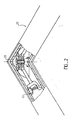
- FIG. 1 reference has been made at 10 to an assembly core placed in one and the other of the cavities 20 and 20 ′ of the two profiles, comprising an external face provided with a housing for screws 11. It also comprises two parallel flat side faces (visible in FIG. 3, where they are referenced 12 and 13), the outline of which has two symmetrical arcs 14 and 14 ′ each intended to come - advantageously, but not necessarily - in contact with the face 21 or 21 'from the cavity located on the outside of the assembly; this outline thus defines two cylinder portions (15 and 15 ′ in FIG. 3), forming rolling surfaces and tangent to the planes formed by the faces 21 and 21 ′.
- the core finally comprises an inner face itself comprising two rectilinear support edges 16 and 16 ′, perpendicular to the planes of the lateral faces 12 and 13, and passing through the axes of the cylinder portions 15 and 15 ′.
- a link 30 is arranged inside the core 10; it is symmetrical, and capable of moving in translation in the direction of the axis 22, bisecting the angle formed by the two sections 20 and 20 ', and materialized by the miter cut.
- the link 30 is connected to two tie rods 40 and 40 'arranged in one and the other of the cavities 20 and 20'.
- Each of these tie rods comprises at one end a hinge 41,41 ′ ensuring the connection with the link 30, and at its other end hooking means which may consist, as in the example described, of retractable pins 42, 42 'penetrating into orifices 22, 22' made in the profiles.
- Springs 43 and 43 ′, integral with the tie rods 40 and 40 ′, ensure that the pin passes from the retracted position to the functional position (pin occupying the orifice of the profile).
- means for tensioning the link consist of two elements 50 and 51 forming a screw and a nut.
- the element 50 is a hexagon socket-head screw coming to press on the inner face of the rod 30, and the element 51 a nut, placed in the housing 11 of the core 10, and therefore coming put pressure on the outside of it.
- the tie rods 40 and 40 ′ are put in place in the cavities 20 and 20 ′ of the sections previously cut with a miter until the pins 42 and 42 ′ are housed in the orifices 22 and 22 '. It can therefore be seen that it is advantageous for contact to be ensured between the outline 14, 14 ′ of the core and the faces 21, 21 ′ of the profiles: a slight friction allows the device to remain in place during the operations of assembly. However, this contact is not necessary to ensure final tightening, and it is possible to design other core shapes that do not have the arcs 14 and 14 ′, without thereby departing from the scope of the invention. We can then energize the clamping means 50 and 51 using a tool inserted into the hole 23.
- the rod 30 will move towards the top of the assembly and cause the approximation, the abutment and tightening of the profiles, on the one hand by a traction exerted on the tie rods and transmitted to the profiles by the pins (represented by the arrows A and A '), on the other hand by a pressure exerted on the edges 16 and 16 '(arrows B and B'); this force, due to the reaction of the core 10 when the screw 50 is tightened on the nut 51, will also tend to bring the two profiles closer together by a pinching effect exerted by the two edges. The effect is more pronounced than the angle is acute.
- the entire device is mounted in a floating manner.
- floating mounting means an assembly which allows, in addition to the translational movement of the link, a play in the relative pivoting of the latter relative to the core, and authorizes the tightening of the assembly even if the link does not is not strictly perpendicular to the angle bisector; the nut 51 then being slightly cantilevered in the cavity 11 of the core.
- Such an assembly makes it possible to compensate on the one hand for any inaccuracies in drilling the orifices 22, 22 ', and on the other hand for a positioning of the core 10 which would not be perfectly symmetrical.
- the device has been shown intended for mounting from the inside. Indeed, the outer sides of the profiles are smooth, and the holes 22 and 22 '(housing of the pins) and 23 (passage of the clamping tool) are made on the inner faces of the profiles.
- FIG. 2 homologous to FIG. 1 for an external tightening, the arrangement is reversed: the internal faces are smooth, and the holes 22, 22 'and 23 are drilled on the external face.
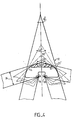
- FIG. 4 explains the preferred shape of the contour 14 of the part 10.
- This part is schematically represented in the cavity of the profiles assembled at 30 ° (thick continuous lines), 60 ° (dotted lines), at right angles (mixed lines ), 120 ° (thin solid lines) and 150 ° (thick solid lines).
- the profiles are supported on the edges 16 and 16 '.
- the device is provided for profiles whose width 24 of the interior cavity, or "module”, has a defined, determined, standardized value, it appears that, if we want the profile to remain in all cases in contact on both sides of its cavity with the part 11, it will be necessary to give the latter, on its outer face, a profile which will be defined as the envelope of the faces 21 and 21 'of the profiles.
- a contour 14 or 14 ′ substantially in the form of an arc of a circle, centered on the edge 16 or 16 ′.
- the two symmetrical arcs of a circle will advantageously have as their radius the value of the module 24 of the profiles to be assembled.
Claims (9)
Applications Claiming Priority (2)
| Application Number | Priority Date | Filing Date | Title |
|---|---|---|---|
| FR8107978A FR2504612A1 (fr) | 1981-04-22 | 1981-04-22 | Dispositif d'assemblage selon un angle quelconque, notamment pour profiles creux |
| FR8107978 | 1981-04-22 |
Publications (3)
| Publication Number | Publication Date |
|---|---|
| EP0064001A2 EP0064001A2 (de) | 1982-11-03 |
| EP0064001A3 EP0064001A3 (en) | 1984-06-20 |
| EP0064001B1 true EP0064001B1 (de) | 1987-01-14 |
Family
ID=9257646
Family Applications (1)
| Application Number | Title | Priority Date | Filing Date |
|---|---|---|---|
| EP82400706A Expired EP0064001B1 (de) | 1981-04-22 | 1982-04-20 | Vorrichtung zum Zusammenfügen unter beliebigem Winkel, insbesondere für hohle Profileisen |
Country Status (5)
| Country | Link |
|---|---|
| EP (1) | EP0064001B1 (de) |
| DE (1) | DE3275113D1 (de) |
| FR (1) | FR2504612A1 (de) |
| MA (1) | MA19452A1 (de) |
| OA (1) | OA07079A (de) |
Cited By (1)
| Publication number | Priority date | Publication date | Assignee | Title |
|---|---|---|---|---|
| US20110176860A1 (en) * | 2010-01-21 | 2011-07-21 | Ruei-Hsing Lin | Structure of connector for aluminum extrusion frame |
Families Citing this family (4)
| Publication number | Priority date | Publication date | Assignee | Title |
|---|---|---|---|---|
| FR2531183B1 (fr) * | 1982-08-02 | 1986-06-06 | Technal France | Dispositif d'assemblage selon un angle quelconque, notamment pour profiles creux |
| FR2715457B1 (fr) * | 1994-01-25 | 1996-04-26 | Coutier Ind | Dispositif de liaison des extrémités adjacentes de deux tronçons de poutre creuse. |
| EP1172511A1 (de) * | 2000-07-10 | 2002-01-16 | L.M. dei F.lli Monticelli S.r.l. | Verbindungselement für Hohlprofile und Verfahren zum montieren |
| KR101852063B1 (ko) * | 2015-10-05 | 2018-06-07 | 민태곤 | 가스 주입 단열 복층유리의 가스누출 방지장치 |
Citations (1)
| Publication number | Priority date | Publication date | Assignee | Title |
|---|---|---|---|---|
| US2994414A (en) * | 1958-01-06 | 1961-08-01 | Paul C Gebhard | Corner fastening for doors, windows and the like |
Family Cites Families (3)
| Publication number | Priority date | Publication date | Assignee | Title |
|---|---|---|---|---|
| CH471310A (de) * | 1968-06-20 | 1969-04-15 | Glissa Ag | Eckverbindungsvorrichtung für Fenster- und Türrahmen |
| FR2378971A2 (fr) * | 1975-11-24 | 1978-08-25 | Technal International Sa | Organe de jonction permettant de realiser un assemblage d'angle |
| DE2609388C3 (de) * | 1976-03-06 | 1980-02-14 | W. Hartmann & Co (Gmbh & Co), 2000 Hamburg | Stabilisienings- und Ausrichtelement fur Gehrungsstoße zwischen zwei Bauprofilen |
-
1981
- 1981-04-22 FR FR8107978A patent/FR2504612A1/fr active Granted
-
1982
- 1982-04-19 MA MA19657A patent/MA19452A1/fr unknown
- 1982-04-20 EP EP82400706A patent/EP0064001B1/de not_active Expired
- 1982-04-20 DE DE8282400706T patent/DE3275113D1/de not_active Expired
- 1982-04-22 OA OA57666A patent/OA07079A/xx unknown
Patent Citations (1)
| Publication number | Priority date | Publication date | Assignee | Title |
|---|---|---|---|---|
| US2994414A (en) * | 1958-01-06 | 1961-08-01 | Paul C Gebhard | Corner fastening for doors, windows and the like |
Cited By (1)
| Publication number | Priority date | Publication date | Assignee | Title |
|---|---|---|---|---|
| US20110176860A1 (en) * | 2010-01-21 | 2011-07-21 | Ruei-Hsing Lin | Structure of connector for aluminum extrusion frame |
Also Published As
| Publication number | Publication date |
|---|---|
| FR2504612A1 (fr) | 1982-10-29 |
| EP0064001A3 (en) | 1984-06-20 |
| EP0064001A2 (de) | 1982-11-03 |
| OA07079A (fr) | 1984-01-31 |
| FR2504612B1 (de) | 1983-07-29 |
| MA19452A1 (fr) | 1982-12-31 |
| DE3275113D1 (en) | 1987-02-19 |
Similar Documents
| Publication | Publication Date | Title |
|---|---|---|
| EP0201455B1 (de) | Federscharnier für Brillen | |
| EP0239440B1 (de) | Einstellungseinrichtung, zum Beispeil für Fahrzeugleuchte | |
| EP0064001B1 (de) | Vorrichtung zum Zusammenfügen unter beliebigem Winkel, insbesondere für hohle Profileisen | |
| FR2654846A1 (fr) | Lunette a branches ou bandeau demontables. | |
| FR2478718A1 (fr) | Dispositif a reglage automatique pour le blocage, en position fermee, d'une porte coulissante d'un vehicule automobile | |
| FR2719269A1 (fr) | Ensemble pour la fixation ajustable selon trois dimensions d'un dispositif d'éclairage et/ou de signalisation de véhicule automobile. | |
| FR2467118A1 (fr) | Balai d'essuie-glace a attache universelle | |
| FR2690760A1 (fr) | Charnière élastique sans vis apparente. | |
| FR2951286A1 (fr) | Monture de lunette | |
| EP0826574A2 (de) | Axial-Verriegelung | |
| EP0100733B1 (de) | Vorrichtung für das Verbinden in einem beliebigen Winkel von insbesondere hohlen Profilen | |
| FR2744482A1 (fr) | Charniere de vantail | |
| EP1059409B1 (de) | Antriebsgetriebe für Schlossnuss | |
| EP0524849A1 (de) | Vorrichtung zum Zusammenbau von Profilschienen | |
| FR2787152A1 (fr) | Dispositif a doigt pour le blocage d'une piece par rapport a une autre | |
| FR2697866A1 (fr) | Lève-vitre pour véhicule automobile. | |
| EP0296961B1 (de) | Befestigungsvorrichtung | |
| EP0932848A1 (de) | Verfahren zur verbindung eines bügels mit einer brillenfassung sowie brillenscharnier | |
| FR2732083A1 (fr) | Dispositif de connexion a montage simplifie pour assembler deux profiles | |
| EP0335443B1 (de) | Befestigungsvorrichtung zum Anbringen eines Elementes auf einer Unterlage, welche nach Befestigung einen nachträglichen Positionsausgleich des Elementes auf der Unterlage zulässt, und Befestigungssystem von zwei Unterlagen, welche Elemente befassen, die mit solchen Befestigungsvorrichtungen ausgestattet sind | |
| FR2647842A1 (fr) | Perfectionnement aux espagnolettes | |
| EP0416981A1 (de) | Verstellbare Stange, insbesondere für Lenkgestänge eines Kraftfahrzeuges | |
| FR2594761A1 (fr) | Dispositif de fixation reglable, notamment pour projecteur de vehicule automobile | |
| FR2562136A1 (fr) | Dispositif d'applique intermediaire entre deux articulations | |
| FR2808598A1 (fr) | Monture de lunettes a branches articulees |
Legal Events
| Date | Code | Title | Description |
|---|---|---|---|
| PUAI | Public reference made under article 153(3) epc to a published international application that has entered the european phase |
Free format text: ORIGINAL CODE: 0009012 |
|
| AK | Designated contracting states |
Designated state(s): BE CH DE FR GB IT LU NL |
|
| PUAL | Search report despatched |
Free format text: ORIGINAL CODE: 0009013 |
|
| AK | Designated contracting states |
Designated state(s): BE CH DE FR GB IT LI LU NL |
|
| 17P | Request for examination filed |
Effective date: 19841105 |
|
| 17Q | First examination report despatched |
Effective date: 19860129 |
|
| GRAA | (expected) grant |
Free format text: ORIGINAL CODE: 0009210 |
|
| ITF | It: translation for a ep patent filed |
Owner name: CON LOR S.R.L. |
|
| AK | Designated contracting states |
Kind code of ref document: B1 Designated state(s): BE CH DE FR GB IT LI LU NL |
|
| REF | Corresponds to: |
Ref document number: 3275113 Country of ref document: DE Date of ref document: 19870219 |
|
| R20 | Corrections of a patent specification |
Effective date: 19870226 |
|
| PLBE | No opposition filed within time limit |
Free format text: ORIGINAL CODE: 0009261 |
|
| STAA | Information on the status of an ep patent application or granted ep patent |
Free format text: STATUS: NO OPPOSITION FILED WITHIN TIME LIMIT |
|
| 26N | No opposition filed | ||
| REG | Reference to a national code |
Ref country code: CH Ref legal event code: PUE Owner name: ALCAN FRANCE |
|
| REG | Reference to a national code |
Ref country code: GB Ref legal event code: 732E |
|
| ITPR | It: changes in ownership of a european patent |
Owner name: FUSIONI;ALUMINIUM ALCAN DE FRANCE |
|
| ITTA | It: last paid annual fee | ||
| EPTA | Lu: last paid annual fee | ||
| BECH | Be: change of holder |
Free format text: 940110 *ALCAN FRANCE |
|
| BECN | Be: change of holder's name |
Effective date: 19940110 |
|
| NLT1 | Nl: modifications of names registered in virtue of documents presented to the patent office pursuant to art. 16 a, paragraph 1 |
Owner name: TECHNAL SA;TECHNAL FRANCE SOCIETE EN NOM COLLECTIF |
|
| NLS | Nl: assignments of ep-patents |
Owner name: ALCAN FRANCE |
|
| PGFP | Annual fee paid to national office [announced via postgrant information from national office to epo] |
Ref country code: LU Payment date: 19960301 Year of fee payment: 15 |
|
| PGFP | Annual fee paid to national office [announced via postgrant information from national office to epo] |
Ref country code: GB Payment date: 19960419 Year of fee payment: 15 |
|
| PGFP | Annual fee paid to national office [announced via postgrant information from national office to epo] |
Ref country code: FR Payment date: 19960422 Year of fee payment: 15 |
|
| PGFP | Annual fee paid to national office [announced via postgrant information from national office to epo] |
Ref country code: NL Payment date: 19960430 Year of fee payment: 15 |
|
| PGFP | Annual fee paid to national office [announced via postgrant information from national office to epo] |
Ref country code: CH Payment date: 19960501 Year of fee payment: 15 |
|
| PGFP | Annual fee paid to national office [announced via postgrant information from national office to epo] |
Ref country code: BE Payment date: 19960513 Year of fee payment: 15 |
|
| PGFP | Annual fee paid to national office [announced via postgrant information from national office to epo] |
Ref country code: DE Payment date: 19960621 Year of fee payment: 15 |
|
| PG25 | Lapsed in a contracting state [announced via postgrant information from national office to epo] |
Ref country code: LU Free format text: LAPSE BECAUSE OF NON-PAYMENT OF DUE FEES Effective date: 19970420 Ref country code: GB Effective date: 19970420 |
|
| PG25 | Lapsed in a contracting state [announced via postgrant information from national office to epo] |
Ref country code: LI Free format text: LAPSE BECAUSE OF NON-PAYMENT OF DUE FEES Effective date: 19970430 Ref country code: CH Free format text: LAPSE BECAUSE OF NON-PAYMENT OF DUE FEES Effective date: 19970430 Ref country code: BE Effective date: 19970430 |
|
| BERE | Be: lapsed |
Owner name: ALCAN FRANCE Effective date: 19970430 |
|
| PG25 | Lapsed in a contracting state [announced via postgrant information from national office to epo] |
Ref country code: NL Effective date: 19971101 |
|
| GBPC | Gb: european patent ceased through non-payment of renewal fee |
Effective date: 19970420 |
|
| REG | Reference to a national code |
Ref country code: CH Ref legal event code: PL |
|
| PG25 | Lapsed in a contracting state [announced via postgrant information from national office to epo] |
Ref country code: FR Free format text: LAPSE BECAUSE OF NON-PAYMENT OF DUE FEES Effective date: 19971231 |
|
| PG25 | Lapsed in a contracting state [announced via postgrant information from national office to epo] |
Ref country code: DE Free format text: LAPSE BECAUSE OF NON-PAYMENT OF DUE FEES Effective date: 19980101 |
|
| NLV4 | Nl: lapsed or anulled due to non-payment of the annual fee |
Effective date: 19971101 |
|
| REG | Reference to a national code |
Ref country code: FR Ref legal event code: ST |