EP0064001B1 - Dispositif d'assemblage selon un angle quelconque, notamment pour profilés creux - Google Patents
Dispositif d'assemblage selon un angle quelconque, notamment pour profilés creux Download PDFInfo
- Publication number
- EP0064001B1 EP0064001B1 EP82400706A EP82400706A EP0064001B1 EP 0064001 B1 EP0064001 B1 EP 0064001B1 EP 82400706 A EP82400706 A EP 82400706A EP 82400706 A EP82400706 A EP 82400706A EP 0064001 B1 EP0064001 B1 EP 0064001B1
- Authority
- EP
- European Patent Office
- Prior art keywords
- core
- connecting rod
- assembly
- profile members
- tie rods
- Prior art date
- Legal status (The legal status is an assumption and is not a legal conclusion. Google has not performed a legal analysis and makes no representation as to the accuracy of the status listed.)
- Expired
Links
- 238000005096 rolling process Methods 0.000 claims description 4
- 238000006073 displacement reaction Methods 0.000 claims 2
- 238000003825 pressing Methods 0.000 claims 2
- 230000001154 acute effect Effects 0.000 description 2
- 230000000712 assembly Effects 0.000 description 2
- 238000000429 assembly Methods 0.000 description 2
- 230000000694 effects Effects 0.000 description 2
- 240000008042 Zea mays Species 0.000 description 1
- 238000006243 chemical reaction Methods 0.000 description 1
- 238000005553 drilling Methods 0.000 description 1
- 239000002184 metal Substances 0.000 description 1
- 238000000034 method Methods 0.000 description 1
- 210000000056 organ Anatomy 0.000 description 1
- 230000000149 penetrating effect Effects 0.000 description 1
- 230000002441 reversible effect Effects 0.000 description 1
- 238000006467 substitution reaction Methods 0.000 description 1
Images


Classifications
-
- E—FIXED CONSTRUCTIONS
- E06—DOORS, WINDOWS, SHUTTERS, OR ROLLER BLINDS IN GENERAL; LADDERS
- E06B—FIXED OR MOVABLE CLOSURES FOR OPENINGS IN BUILDINGS, VEHICLES, FENCES OR LIKE ENCLOSURES IN GENERAL, e.g. DOORS, WINDOWS, BLINDS, GATES
- E06B3/00—Window sashes, door leaves, or like elements for closing wall or like openings; Layout of fixed or moving closures, e.g. windows in wall or like openings; Features of rigidly-mounted outer frames relating to the mounting of wing frames
- E06B3/96—Corner joints or edge joints for windows, doors, or the like frames or wings
- E06B3/964—Corner joints or edge joints for windows, doors, or the like frames or wings using separate connection pieces, e.g. T-connection pieces
- E06B3/968—Corner joints or edge joints for windows, doors, or the like frames or wings using separate connection pieces, e.g. T-connection pieces characterised by the way the connecting pieces are fixed in or on the frame members
- E06B3/98—Corner joints or edge joints for windows, doors, or the like frames or wings using separate connection pieces, e.g. T-connection pieces characterised by the way the connecting pieces are fixed in or on the frame members the connecting pieces being specially adapted for drawing the frame members towards each other
- E06B3/982—Mitre joints
-
- E—FIXED CONSTRUCTIONS
- E06—DOORS, WINDOWS, SHUTTERS, OR ROLLER BLINDS IN GENERAL; LADDERS
- E06B—FIXED OR MOVABLE CLOSURES FOR OPENINGS IN BUILDINGS, VEHICLES, FENCES OR LIKE ENCLOSURES IN GENERAL, e.g. DOORS, WINDOWS, BLINDS, GATES
- E06B3/00—Window sashes, door leaves, or like elements for closing wall or like openings; Layout of fixed or moving closures, e.g. windows in wall or like openings; Features of rigidly-mounted outer frames relating to the mounting of wing frames
- E06B3/96—Corner joints or edge joints for windows, doors, or the like frames or wings
- E06B3/964—Corner joints or edge joints for windows, doors, or the like frames or wings using separate connection pieces, e.g. T-connection pieces
- E06B3/9644—L-shaped corner pieces having two articulated or flexible joined legs; Corner joints with variable angle
-
- F—MECHANICAL ENGINEERING; LIGHTING; HEATING; WEAPONS; BLASTING
- F16—ENGINEERING ELEMENTS AND UNITS; GENERAL MEASURES FOR PRODUCING AND MAINTAINING EFFECTIVE FUNCTIONING OF MACHINES OR INSTALLATIONS; THERMAL INSULATION IN GENERAL
- F16B—DEVICES FOR FASTENING OR SECURING CONSTRUCTIONAL ELEMENTS OR MACHINE PARTS TOGETHER, e.g. NAILS, BOLTS, CIRCLIPS, CLAMPS, CLIPS OR WEDGES; JOINTS OR JOINTING
- F16B7/00—Connections of rods or tubes, e.g. of non-circular section, mutually, including resilient connections
- F16B7/04—Clamping or clipping connections
Definitions
- the present invention relates to a device for assembling two hollow sections, in particular metal sections, whether they are of the so-called “tubular” type (with closed section) or of the so-called “quasi-tubular” type (with open section).
- Miter cut will be understood to mean a bevel cut of both sections, so that the line of cut constitutes the bisector of an assembly angle of any value, acute or obtuse, without the term "tab” in any way suggesting a restriction to a right angle).
- a first type of these devices imposes a right angle by means of L-shaped parts or the like, rigid, placed inside one and the other of the profiles to be assembled and made integral with the latter.
- Another type of device allows a slight tolerance on the right angle, proceeding by bringing together and tightening two sections against each other, the accuracy of the right angle being ensured by the precision of the miter cut.
- devices of this type can use either a slightly deformable square, or (such as that of US-A-2 994414) two tie rods arranged symmetrically, the respective first ends of which are connected by an articulated connection, and comprising at their respective second end means of attachment to the profiles.
- the device according to the invention unlike the previous devices, but retaining their advantages, makes it possible to produce assemblies at an angle which can vary within very large proportions.
- a universal device such as that described below makes it easy to produce assemblies whose angle can take any value between 30 ° and 150 °.
- the accuracy of the angle chosen is ensured by the precision of the miter cut, precision which can be obtained quite satisfactorily with conventional section cutting techniques.
- the tab once produced, and the profiles in place, the device according to the invention will carry out in a single operation the bringing together, the abutment, and the tightening thereof, thereby ensuring immobilization of the assembly.
- the device according to the invention which is of the same type as that of the aforementioned US-A-2 994 414, comprises: an assembly core capable of cooperating with the internal faces of the profiles according to a rolling surface, on the side of the top of the connection angle, and along two support and pivoting edges, on the side opposite the top of the connection angle; a link capable of moving inside the core in a translational movement towards the top of the assembly, this link connecting together with articulation the first ends of the tie rods; and means for ensuring the relative movement of the rod relative to the core.
- these two elements have the same external dimensions, so that one or the other can be indifferently placed in a housing formed in the part of the core located on the external side of the assembly.
- the screw head can be presented either inward or outward of the assembly, so as to allow the tensioning of the device with a tool inserted through an orifice made in the face of the profile, inside or outside, opposite the screw head.
- the means for attaching the tie rods to the profiles advantageously comprise at least one pin, preferably retractable, integral with the tie rod, and capable of being introduced into an orifice. practiced in the profile.
- the rod-tie assembly is capable of being turned over so as to be able to introduce the pins into orifices made either on a determined face - for example, the inner face - of the profiles, or on the other face. - for example, the outer face - thus ensuring the reversibility mentioned above.
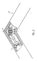
- FIG. 1 reference has been made at 10 to an assembly core placed in one and the other of the cavities 20 and 20 ′ of the two profiles, comprising an external face provided with a housing for screws 11. It also comprises two parallel flat side faces (visible in FIG. 3, where they are referenced 12 and 13), the outline of which has two symmetrical arcs 14 and 14 ′ each intended to come - advantageously, but not necessarily - in contact with the face 21 or 21 'from the cavity located on the outside of the assembly; this outline thus defines two cylinder portions (15 and 15 ′ in FIG. 3), forming rolling surfaces and tangent to the planes formed by the faces 21 and 21 ′.
- the core finally comprises an inner face itself comprising two rectilinear support edges 16 and 16 ′, perpendicular to the planes of the lateral faces 12 and 13, and passing through the axes of the cylinder portions 15 and 15 ′.
- a link 30 is arranged inside the core 10; it is symmetrical, and capable of moving in translation in the direction of the axis 22, bisecting the angle formed by the two sections 20 and 20 ', and materialized by the miter cut.
- the link 30 is connected to two tie rods 40 and 40 'arranged in one and the other of the cavities 20 and 20'.
- Each of these tie rods comprises at one end a hinge 41,41 ′ ensuring the connection with the link 30, and at its other end hooking means which may consist, as in the example described, of retractable pins 42, 42 'penetrating into orifices 22, 22' made in the profiles.
- Springs 43 and 43 ′, integral with the tie rods 40 and 40 ′, ensure that the pin passes from the retracted position to the functional position (pin occupying the orifice of the profile).
- means for tensioning the link consist of two elements 50 and 51 forming a screw and a nut.
- the element 50 is a hexagon socket-head screw coming to press on the inner face of the rod 30, and the element 51 a nut, placed in the housing 11 of the core 10, and therefore coming put pressure on the outside of it.
- the tie rods 40 and 40 ′ are put in place in the cavities 20 and 20 ′ of the sections previously cut with a miter until the pins 42 and 42 ′ are housed in the orifices 22 and 22 '. It can therefore be seen that it is advantageous for contact to be ensured between the outline 14, 14 ′ of the core and the faces 21, 21 ′ of the profiles: a slight friction allows the device to remain in place during the operations of assembly. However, this contact is not necessary to ensure final tightening, and it is possible to design other core shapes that do not have the arcs 14 and 14 ′, without thereby departing from the scope of the invention. We can then energize the clamping means 50 and 51 using a tool inserted into the hole 23.
- the rod 30 will move towards the top of the assembly and cause the approximation, the abutment and tightening of the profiles, on the one hand by a traction exerted on the tie rods and transmitted to the profiles by the pins (represented by the arrows A and A '), on the other hand by a pressure exerted on the edges 16 and 16 '(arrows B and B'); this force, due to the reaction of the core 10 when the screw 50 is tightened on the nut 51, will also tend to bring the two profiles closer together by a pinching effect exerted by the two edges. The effect is more pronounced than the angle is acute.
- the entire device is mounted in a floating manner.
- floating mounting means an assembly which allows, in addition to the translational movement of the link, a play in the relative pivoting of the latter relative to the core, and authorizes the tightening of the assembly even if the link does not is not strictly perpendicular to the angle bisector; the nut 51 then being slightly cantilevered in the cavity 11 of the core.
- Such an assembly makes it possible to compensate on the one hand for any inaccuracies in drilling the orifices 22, 22 ', and on the other hand for a positioning of the core 10 which would not be perfectly symmetrical.
- the device has been shown intended for mounting from the inside. Indeed, the outer sides of the profiles are smooth, and the holes 22 and 22 '(housing of the pins) and 23 (passage of the clamping tool) are made on the inner faces of the profiles.
- FIG. 2 homologous to FIG. 1 for an external tightening, the arrangement is reversed: the internal faces are smooth, and the holes 22, 22 'and 23 are drilled on the external face.
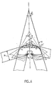
- FIG. 4 explains the preferred shape of the contour 14 of the part 10.
- This part is schematically represented in the cavity of the profiles assembled at 30 ° (thick continuous lines), 60 ° (dotted lines), at right angles (mixed lines ), 120 ° (thin solid lines) and 150 ° (thick solid lines).
- the profiles are supported on the edges 16 and 16 '.
- the device is provided for profiles whose width 24 of the interior cavity, or "module”, has a defined, determined, standardized value, it appears that, if we want the profile to remain in all cases in contact on both sides of its cavity with the part 11, it will be necessary to give the latter, on its outer face, a profile which will be defined as the envelope of the faces 21 and 21 'of the profiles.
- a contour 14 or 14 ′ substantially in the form of an arc of a circle, centered on the edge 16 or 16 ′.
- the two symmetrical arcs of a circle will advantageously have as their radius the value of the module 24 of the profiles to be assembled.
Landscapes
- Engineering & Computer Science (AREA)
- General Engineering & Computer Science (AREA)
- Civil Engineering (AREA)
- Structural Engineering (AREA)
- Mechanical Engineering (AREA)
- Mutual Connection Of Rods And Tubes (AREA)
Description
- La présente invention concerne un dispositif d'assemblage de deux profilés creux, notamment de profilés métalliques, qu'ils soient du type dit "tubulaire" (à section fermée) ou du type dit "quasi-tubulaire" (à section ouverte).
- Divers dispositifs connus permettent, lorsqu'il s'agit de former un angle, de réaliser un assemblage par rapprochement et mise en butée de deux profilés préalablement coupés d'onglet. (On entendra par "coupe d'onglet" une coupe en biseau de l'un et l'autre profilés, de telle sorte que la ligne de coupe constitue la bissectrice d'un angle d'assemblage de valeur quelconque, aigu ou obtus, sans que le terme d"'onglet" ne suggère d'aucune façon une restriction à un angle droit).
- Ces divers dispositifs donnent pleinement satisfaction, mais ils ne sont prévus que pour un assemblage d'angle prédéterminé, le plus souvent un angle droit. Un premier type de ces dispositifs impose un angle droit par l'intermédiaire de pièces en forme de L ou analogues, rigides, placées à l'intérieur de l'un et l'autre des profilés à assembler et rendues solidaires de ces derniers. Un autre type de dispositif autorise une légère tolérance sur l'angle droit, en procédant par rapprochement et serrage de deux profilés l'un contre l'autre l'exactitude de l'angle droit étant assurée par la précision de la coupe d'onglet; les dispositifs de ce type peuvent utiliser soit une équerre légèrement déformable, soit (tel celui du US-A- 2 994414) deux tirants disposés symétriquement, dont les premières extrémités respectives sont reliées par une liaison articulée, et comportant à leur seconde extrémité respective des moyens d'accrochage aux profilés.
- Le dispositif selon l'invention, au contraire des précédents dispositifs, mais en conservant leurs avantages, permet de réaliser des assemblages selon un angle pouvant varier dans de très larges proportions. Par exemple, et à titre non limitatif, un dispositif universel tel que celui décrit ci-dessous permet de réaliser aisément des assemblages dont l'angle peut prendre toute valeur comprise entre 30° et 150°. L'exactitude de l'angle choisi est assurée par la précision de la coupe d'onglet, précision qu'il est possible d'obtenir de manière tout à fait satisfaisante avec les techniques classiques de sectionnement des profilés. L'onglet une fois réalisé, et les profilés mis en place, le dispositif selon l'invention va réaliser en une seule opération le rapprochement, la mise en butée, et le serrage de ceux-ci, assurant par voie de conséquence l'immobilisation de l'assemblage.
- Sa conception lui permet en outre d'être totalement dissimulé à l'intérieur des cavités des deux profilés, même lorsque ceux-ci font un angle très aigu, ne laissant apparaître sur la surface extérieure aucune pièce ou organe proéminent révélant sa présence. Les seuls éléments apparents sur les profilés sont des perçages dont le rôle sera explicité plus bas. Mais la conception du présent dispositif le rend réversible, c'est-à-dire qu'il est possible d'assembler des profilés dont les perçages peuvent être situés indifféremment sur la face de l'assemblage située du côté du sommet de l'angle de raccordement (qu'on désignera par la suite "côté extérieur") ou sur la face située du côté opposé ("côté intérieur"). Il est ainsi possible d'assembler par le côté intérieur des profilés, de façon à laisser une face extérieure lisse - ou inversement. En variante, il est même possible d'envisager un dispositif selon l'invention utilisant des perçages sur les faces latérales, ou même doté de moyens d'accrochage totalement dissimulés. La commodité d'emploi du dispositif lui permet ainsi de s'adapter à la plupart des situations rencontrées couramment au cours du montage des profilés.
- A cette fin, le dispositif selon l'invention, qui est du même type que celui du US-A- 2 994 414 précité, comporte: un noyau d'assemblage susceptible de coopérer avec les faces intérieures des profilés selon une surface de roulement, du côté du sommet de l'angle de raccordement, et selon deux arêtes d'appui et de pivotement, du côté opposé au sommet de l'angle de raccordement; une biellette susceptible de se déplacer à l'intérieur du noyau selon un mouvement de translation en direction du sommet de l'assemblage, cette biellette reliant ensemble avec articulation les premières extrémités des tirants; et des moyens pour assurer le déplacement relatif de la biellette par rapport au noyau.
- Ces derniers moyens sont eux-mêmes constitués de deux éléments formant vis et écrou, la tête de l'un des éléments venant faire pression sur la face extérieure du noyau, et la tête de l'autre élément venant faire pression sur la face intérieure de la biellette, de manière que la mise sous tension de ces deux éléments assure le rapprochement et la mise en butée des profilés, à la fois par une traction transmise par la biellette à l'un et l'autre des tirants, et par une pression exercée sur les arêtes d'appui du noyau.
- De plus, ces deux éléments sont de mêmes dimensions extérieures, de manière que l'un ou l'autre puisse être indifféremment mis en place dans un logement pratiqué dans la partie du noyau situé du côté extérieur de l'assemblage. C'est ainsi que, par démontage et permutation de la vis et de l'écrou, on pourra présenter la tête de vis soit vers l'intérieur, soit vers l'extérieur de l'assemblage, de manière à permettre la mise sous tension du dispositif avec un outil introduit par un orifice pratiqué dans la face du profilé, intérieure ou extérieure, en regard de la tête de vis.
- Pour permettre un démontage aisé, les moyens d'accrochage des tirants aux profilés comportent avantageusement au moins un pion, de préférence rétractable, solidaire du tirant, et susceptible d'être introduit dans un orifice pratiqué dans le profilé.
- De manière également avantageuse, l'ensemble biellette-tirants est susceptible d'être retourné de manière à pouvoir introduire les pions dans des orifices pratiqués soit sur une face déterminée - par exemple, la face intérieure - des profilés, soit sur l'autre face - par exemple, la face extérieure - assurant ainsi la réversibilité évoquée plus haut.
- D'autres caractéristiques et avantages de l'invention apparaîtront à la lecture de la description ci-dessous, faite en référence aux dessins annexés, où:
- - la figure 1 représente une vue en coupe du dispositif selon l'invention, en place dans l'assemblage, où la fixation et le serrage sont réalisés du côté intérieur de l'assemblage.
- - la figure 2 représente la même figure, mais avec la fixation et le serrage réalisés du côté extérieur de l'assemblage.
- - la figure 3 est une vue en perspective de l'ensemble avant son assemblage (montage par l'extérieur).
- - la figure 4 montre le positionnement de la pièce centrale du dispositif pour différentes valeurs de l'angle d'assemblage.
- Sur la figure 1, on a référencé en 10 un noyau d'assemblage placé dans l'une et l'autre des cavités 20 et 20' des deux profilés, comportant une face extérieure munie d'un logement de vis 11. Il comporte également deux faces latérales planes parallèles (visibles sur la figure 3, où elles sont référencées 12 et 13) dont le contour présente deux arcs de cercle 14 et 14' symétriques destinés chacun à venir - avantageusement, mais non nécessairement - en contact avec la face 21 ou 21' de la cavité située du côté extérieur de l'assemblage; ce contour définit ainsi deux portions de cylindre (15 et 15' sur la figure 3), formant surfaces de roulement et tangentes aux plans constitués par les faces 21 et 21'. Le noyau comporte enfin une face intérieure comportant elle-même deux arêtes d'appui rectilignes 16 et 16', perpendiculaires aux plans des faces latérales 12 et 13, et passant par les axes des portions de cylindre 15 et 15'.
- Une biellette 30 est disposée à l'intérieur du noyau 10; elle est symétrique, et susceptible de se déplacer en translation dans la direction de l'axe 22, bissectrice de l'angle formé par les deux profilés 20 et 20', et matérialisé par la coupe d'onglet.
- La biellette 30 est reliée à deux tirants 40 et 40' disposés dans l'une et l'autre des cavités 20 et 20'. Chacun de ces tirants comporte à une extrémité une articulation 41,41' assurant la liaison avec la biellette 30, et à son autre extrémité des moyens d'accrochage qui peuvent être constitués, comme dans l'exemple décrit, de pions rétractables 42, 42' pénétrant dans des orifices 22, 22' pratiqués dans les profilés. Des ressorts 43 et 43', solidaires des tirants 40 et 40', assurent au pion le passage de la position rétractée à la position fonctionnelle (pion occupant l'orifice du profilé).
- Enfin, des moyens de mise sous tension de la biellette sont constitués de deux éléments 50 et 51 formant vis et écrou. Sur la figure 1, l'élément 50 est une vis à tête creuse à 6 pans venant faire pression sur la face intérieure de la biellette 30, et l'élément 51 un écrou, placé dans le logement 11 du noyau 10, et venant donc faire pression sur la face extérieure de celui-ci.
- Pour réaliser l'assemblage, on met en place les tirants 40 et 40' dans les cavités 20 et 20' des profilés préalablement coupés d'onglet jusqu'à ce que les pions 42 et 42' viennent se loger dans les orifices 22 et 22'. On conçoit alors qu'il est avantageux qu'un contact soit assuré entre le contour 14, 14' du noyau et les faces 21, 21' des profilés: un léger frottement permet que le dispositif se maintienne en place au cours des opérations d'assemblage. Mais ce contact n'est pas nécessaire pour assurer le serrage final, et il est possible de concevoir d'autres formes de noyau ne présentant pas les arcs de cercle 14 et 14', sans pour autant sortir du domaine de l'invention. On peut alors mettre sous tension les moyens de serrage 50 et 51 à l'aide d'un outil introduit dans le trou 23. De cette manière, la biellette 30 va se déplacer vers le sommet de l'assemblage et provoquer le rapprochement, la mise en butée et le serrage des profilés, d'une part par une traction exercée sur les tirants et transmise aux profilés par les pions (représentée par les flèches A et A'), d'autre part par une pression exercée sur les arêtes 16 et 16' (flèches B et B') ; cet effort, dû à la réaction du noyau 10 au moment du serrage de la vis 50 sur l'écrou 51, va également tendre à rapprocher les deux profilés par un effet de pincement exercé par les deux arêtes. L'effet est d'autant plus prononcé que l'angle est aigu.
- Avantageusement, l'ensemble du dispositif est monté de manière flottante. Par "montage flottant", on entend un assemblage qui permet, outre le mouvement de translation de la biellette, un jeu au pivotement relatif de celle-ci par rapport au noyau, et autorise le serrage de l'assemblage même si la biellette n'est pas rigoureusement perpendiculaire à la bissectrice de l'angle; l'écrou 51 étant alors légèrement en porte-à-faux dans la cavité 11 du noyau. Un tel montage permet de rattraper d'une part d'éventuelles imprécisions de perçage des orifices 22, 22', et d'autre part un positionnement du noyau 10 qui ne serait pas parfaitement symétrique.
- Sur la figure 1, le dispositif a été représenté prévu pour un montage par l'intérieur. En effet, les côtés extérieurs des profilés sont lisses, et les trous 22 et 22' (logements des pions) et 23 (passage de l'outil de serrage) sont pratiqués sur les faces intérieures des profilés.
- Par contre, sur la figure 2, homologue de la figure 1 pour un serrage extérieur, la disposition est inversée: les faces intérieures sont lisses, et les trous 22, 22' et 23 sont percés sur la face extérieure.
- Pour passer d'un montage à l'autre, il suffit de démonter la vis 50 et l'écrou 51, retourner l'ensemble tirants-biellette de manière à présenter les pions vers l'extérieur, puis permuter la vis et l'écrou (la substitution est possible si la tête de la vis 50, et l'écrou 51 ont mêmes dimensions extérieures, de manière que l'un ou l'autre puisse être indifféremment placé dans le logement 11 que présente le noyau 10).
- On constate ainsi la réversibilité du dispositif selon l'invention, un ensemble unique permettant, par démontage et permutation de deux pièces, de réaliser un assemblage, soit par l'intérieur, soit par l'extérieur.
- La figure 4 explicite la forme préférée du contour 14 de la pièce 10. On a représenté schématiquement cette pièce placée dans la cavité des profilés assemblés à 30° (traits continus épais), 60° (traits pointillés), à angle droit (traits mixtes), à 120° (traits continus fins) et à 150° (traits continus épais). En toute hypothèse, les profilés prennent appui sur les arêtes 16 et 16'. Comme le dispositif est prévu pour des profilés dont la largeur 24 de la cavité intérieure, ou "module", a une valeur définie déterminée, normalisée, il apparaît que, si l'on veut que le profilé reste dans tous les cas de figure en contact sur les deux faces de sa cavité avec la pièce 11, il faudra donner à cette dernière, sur sa face extérieure, un profil qui sera défini comme l'enveloppe des faces 21 et 21' des profilés. On détermine ainsi, de façon caractéristique de l'invention, un contour 14 ou 14' sensiblement en forme d'arc de cercle, centré sur l'arête 16 ou 16'. Les deux arcs de cercle, symétriques, auront avantageusement pour rayon la valeur du module 24 des profilés à assembler.
Claims (9)
caractérisé en ce qu'il comporte en outre:
Applications Claiming Priority (2)
| Application Number | Priority Date | Filing Date | Title |
|---|---|---|---|
| FR8107978A FR2504612A1 (fr) | 1981-04-22 | 1981-04-22 | Dispositif d'assemblage selon un angle quelconque, notamment pour profiles creux |
| FR8107978 | 1981-04-22 |
Publications (3)
| Publication Number | Publication Date |
|---|---|
| EP0064001A2 EP0064001A2 (fr) | 1982-11-03 |
| EP0064001A3 EP0064001A3 (en) | 1984-06-20 |
| EP0064001B1 true EP0064001B1 (fr) | 1987-01-14 |
Family
ID=9257646
Family Applications (1)
| Application Number | Title | Priority Date | Filing Date |
|---|---|---|---|
| EP82400706A Expired EP0064001B1 (fr) | 1981-04-22 | 1982-04-20 | Dispositif d'assemblage selon un angle quelconque, notamment pour profilés creux |
Country Status (5)
| Country | Link |
|---|---|
| EP (1) | EP0064001B1 (fr) |
| DE (1) | DE3275113D1 (fr) |
| FR (1) | FR2504612A1 (fr) |
| MA (1) | MA19452A1 (fr) |
| OA (1) | OA07079A (fr) |
Cited By (1)
| Publication number | Priority date | Publication date | Assignee | Title |
|---|---|---|---|---|
| US20110176860A1 (en) * | 2010-01-21 | 2011-07-21 | Ruei-Hsing Lin | Structure of connector for aluminum extrusion frame |
Families Citing this family (4)
| Publication number | Priority date | Publication date | Assignee | Title |
|---|---|---|---|---|
| FR2531183B1 (fr) * | 1982-08-02 | 1986-06-06 | Technal France | Dispositif d'assemblage selon un angle quelconque, notamment pour profiles creux |
| FR2715457B1 (fr) * | 1994-01-25 | 1996-04-26 | Coutier Ind | Dispositif de liaison des extrémités adjacentes de deux tronçons de poutre creuse. |
| EP1172511A1 (fr) * | 2000-07-10 | 2002-01-16 | L.M. dei F.lli Monticelli S.r.l. | Elément de connexion pour sections tubulaires et procédé d'assemblage |
| KR101852063B1 (ko) * | 2015-10-05 | 2018-06-07 | 민태곤 | 가스 주입 단열 복층유리의 가스누출 방지장치 |
Citations (1)
| Publication number | Priority date | Publication date | Assignee | Title |
|---|---|---|---|---|
| US2994414A (en) * | 1958-01-06 | 1961-08-01 | Paul C Gebhard | Corner fastening for doors, windows and the like |
Family Cites Families (3)
| Publication number | Priority date | Publication date | Assignee | Title |
|---|---|---|---|---|
| CH471310A (de) * | 1968-06-20 | 1969-04-15 | Glissa Ag | Eckverbindungsvorrichtung für Fenster- und Türrahmen |
| FR2378971A2 (fr) * | 1975-11-24 | 1978-08-25 | Technal International Sa | Organe de jonction permettant de realiser un assemblage d'angle |
| DE2609388C3 (de) * | 1976-03-06 | 1980-02-14 | W. Hartmann & Co (Gmbh & Co), 2000 Hamburg | Stabilisienings- und Ausrichtelement fur Gehrungsstoße zwischen zwei Bauprofilen |
-
1981
- 1981-04-22 FR FR8107978A patent/FR2504612A1/fr active Granted
-
1982
- 1982-04-19 MA MA19657A patent/MA19452A1/fr unknown
- 1982-04-20 EP EP82400706A patent/EP0064001B1/fr not_active Expired
- 1982-04-20 DE DE8282400706T patent/DE3275113D1/de not_active Expired
- 1982-04-22 OA OA57666A patent/OA07079A/fr unknown
Patent Citations (1)
| Publication number | Priority date | Publication date | Assignee | Title |
|---|---|---|---|---|
| US2994414A (en) * | 1958-01-06 | 1961-08-01 | Paul C Gebhard | Corner fastening for doors, windows and the like |
Cited By (1)
| Publication number | Priority date | Publication date | Assignee | Title |
|---|---|---|---|---|
| US20110176860A1 (en) * | 2010-01-21 | 2011-07-21 | Ruei-Hsing Lin | Structure of connector for aluminum extrusion frame |
Also Published As
| Publication number | Publication date |
|---|---|
| MA19452A1 (fr) | 1982-12-31 |
| FR2504612B1 (fr) | 1983-07-29 |
| FR2504612A1 (fr) | 1982-10-29 |
| EP0064001A3 (en) | 1984-06-20 |
| OA07079A (fr) | 1984-01-31 |
| DE3275113D1 (en) | 1987-02-19 |
| EP0064001A2 (fr) | 1982-11-03 |
Similar Documents
| Publication | Publication Date | Title |
|---|---|---|
| EP0201455B1 (fr) | Charnière élastique pour lunettes | |
| EP0239440B1 (fr) | Dispositif de fixation réglable, notamment pour projecteur de véhicule | |
| EP0064001B1 (fr) | Dispositif d'assemblage selon un angle quelconque, notamment pour profilés creux | |
| FR2654846A1 (fr) | Lunette a branches ou bandeau demontables. | |
| FR2478718A1 (fr) | Dispositif a reglage automatique pour le blocage, en position fermee, d'une porte coulissante d'un vehicule automobile | |
| EP0679553A1 (fr) | Ensemble pour la fixation ajustable selon trois dimensions d'un dispositif d'éclairage et/ou de signalisation de véhicule automobile | |
| FR2467118A1 (fr) | Balai d'essuie-glace a attache universelle | |
| FR2690760A1 (fr) | Charnière élastique sans vis apparente. | |
| FR2951286A1 (fr) | Monture de lunette | |
| EP0826574A2 (fr) | Système de verrouillage axial | |
| EP0100733B1 (fr) | Dispositif d'assemblage selon un angle quelconque, notamment pour profilés creux | |
| FR2744482A1 (fr) | Charniere de vantail | |
| FR2794787A1 (fr) | Dispositif de renvoi de fouillot | |
| EP0524849A1 (fr) | Dispositif d'assemblage de profilés | |
| EP0296961B1 (fr) | Dispositif de fixation | |
| FR2787152A1 (fr) | Dispositif a doigt pour le blocage d'une piece par rapport a une autre | |
| FR2697866A1 (fr) | Lève-vitre pour véhicule automobile. | |
| EP0932848A1 (fr) | Procede de liaison entre une branche et une fa ade de lunettes et charniere de lunettes | |
| EP0246977B1 (fr) | Plaque-cliché immobilisée sur un cylindre support d'une imprimeuse rotative | |
| FR2732083A1 (fr) | Dispositif de connexion a montage simplifie pour assembler deux profiles | |
| EP0335443B1 (fr) | Dispositif d'assemblage pour l'accrochage d'un élément sur un support, adapte pour permettre d'ajuster après assemblage la position dudit élément sur ledit support et système d'assemblage de deux supports comportant des éléments dotés de tels dispositifs d'assemblage | |
| EP0416981A1 (fr) | Biellette réglable, en particulier pour la tringlerie de direction d'une automobile | |
| FR2594761A1 (fr) | Dispositif de fixation reglable, notamment pour projecteur de vehicule automobile | |
| FR2808598A1 (fr) | Monture de lunettes a branches articulees | |
| FR2682739A1 (fr) | Equerre d'assemblage de deux profiles metalliques. |
Legal Events
| Date | Code | Title | Description |
|---|---|---|---|
| PUAI | Public reference made under article 153(3) epc to a published international application that has entered the european phase |
Free format text: ORIGINAL CODE: 0009012 |
|
| AK | Designated contracting states |
Designated state(s): BE CH DE FR GB IT LU NL |
|
| PUAL | Search report despatched |
Free format text: ORIGINAL CODE: 0009013 |
|
| AK | Designated contracting states |
Designated state(s): BE CH DE FR GB IT LI LU NL |
|
| 17P | Request for examination filed |
Effective date: 19841105 |
|
| 17Q | First examination report despatched |
Effective date: 19860129 |
|
| GRAA | (expected) grant |
Free format text: ORIGINAL CODE: 0009210 |
|
| ITF | It: translation for a ep patent filed |
Owner name: CON LOR S.R.L. |
|
| AK | Designated contracting states |
Kind code of ref document: B1 Designated state(s): BE CH DE FR GB IT LI LU NL |
|
| REF | Corresponds to: |
Ref document number: 3275113 Country of ref document: DE Date of ref document: 19870219 |
|
| R20 | Corrections of a patent specification |
Effective date: 19870226 |
|
| PLBE | No opposition filed within time limit |
Free format text: ORIGINAL CODE: 0009261 |
|
| STAA | Information on the status of an ep patent application or granted ep patent |
Free format text: STATUS: NO OPPOSITION FILED WITHIN TIME LIMIT |
|
| 26N | No opposition filed | ||
| REG | Reference to a national code |
Ref country code: CH Ref legal event code: PUE Owner name: ALCAN FRANCE |
|
| REG | Reference to a national code |
Ref country code: GB Ref legal event code: 732E |
|
| ITPR | It: changes in ownership of a european patent |
Owner name: FUSIONI;ALUMINIUM ALCAN DE FRANCE |
|
| ITTA | It: last paid annual fee | ||
| EPTA | Lu: last paid annual fee | ||
| BECH | Be: change of holder |
Free format text: 940110 *ALCAN FRANCE |
|
| BECN | Be: change of holder's name |
Effective date: 19940110 |
|
| NLT1 | Nl: modifications of names registered in virtue of documents presented to the patent office pursuant to art. 16 a, paragraph 1 |
Owner name: TECHNAL SA;TECHNAL FRANCE SOCIETE EN NOM COLLECTIF |
|
| NLS | Nl: assignments of ep-patents |
Owner name: ALCAN FRANCE |
|
| PGFP | Annual fee paid to national office [announced via postgrant information from national office to epo] |
Ref country code: LU Payment date: 19960301 Year of fee payment: 15 |
|
| PGFP | Annual fee paid to national office [announced via postgrant information from national office to epo] |
Ref country code: GB Payment date: 19960419 Year of fee payment: 15 |
|
| PGFP | Annual fee paid to national office [announced via postgrant information from national office to epo] |
Ref country code: FR Payment date: 19960422 Year of fee payment: 15 |
|
| PGFP | Annual fee paid to national office [announced via postgrant information from national office to epo] |
Ref country code: NL Payment date: 19960430 Year of fee payment: 15 |
|
| PGFP | Annual fee paid to national office [announced via postgrant information from national office to epo] |
Ref country code: CH Payment date: 19960501 Year of fee payment: 15 |
|
| PGFP | Annual fee paid to national office [announced via postgrant information from national office to epo] |
Ref country code: BE Payment date: 19960513 Year of fee payment: 15 |
|
| PGFP | Annual fee paid to national office [announced via postgrant information from national office to epo] |
Ref country code: DE Payment date: 19960621 Year of fee payment: 15 |
|
| PG25 | Lapsed in a contracting state [announced via postgrant information from national office to epo] |
Ref country code: LU Free format text: LAPSE BECAUSE OF NON-PAYMENT OF DUE FEES Effective date: 19970420 Ref country code: GB Effective date: 19970420 |
|
| PG25 | Lapsed in a contracting state [announced via postgrant information from national office to epo] |
Ref country code: LI Free format text: LAPSE BECAUSE OF NON-PAYMENT OF DUE FEES Effective date: 19970430 Ref country code: CH Free format text: LAPSE BECAUSE OF NON-PAYMENT OF DUE FEES Effective date: 19970430 Ref country code: BE Effective date: 19970430 |
|
| BERE | Be: lapsed |
Owner name: ALCAN FRANCE Effective date: 19970430 |
|
| PG25 | Lapsed in a contracting state [announced via postgrant information from national office to epo] |
Ref country code: NL Effective date: 19971101 |
|
| GBPC | Gb: european patent ceased through non-payment of renewal fee |
Effective date: 19970420 |
|
| REG | Reference to a national code |
Ref country code: CH Ref legal event code: PL |
|
| PG25 | Lapsed in a contracting state [announced via postgrant information from national office to epo] |
Ref country code: FR Free format text: LAPSE BECAUSE OF NON-PAYMENT OF DUE FEES Effective date: 19971231 |
|
| PG25 | Lapsed in a contracting state [announced via postgrant information from national office to epo] |
Ref country code: DE Free format text: LAPSE BECAUSE OF NON-PAYMENT OF DUE FEES Effective date: 19980101 |
|
| NLV4 | Nl: lapsed or anulled due to non-payment of the annual fee |
Effective date: 19971101 |
|
| REG | Reference to a national code |
Ref country code: FR Ref legal event code: ST |