EP0063484A2 - Behälterformer und Klebemaschine, die einen schnell und kalt erhärtenden Klebstoff verwendet - Google Patents
Behälterformer und Klebemaschine, die einen schnell und kalt erhärtenden Klebstoff verwendet Download PDFInfo
- Publication number
- EP0063484A2 EP0063484A2 EP82301970A EP82301970A EP0063484A2 EP 0063484 A2 EP0063484 A2 EP 0063484A2 EP 82301970 A EP82301970 A EP 82301970A EP 82301970 A EP82301970 A EP 82301970A EP 0063484 A2 EP0063484 A2 EP 0063484A2
- Authority
- EP
- European Patent Office
- Prior art keywords
- case
- adhesive
- flaps
- pins
- major
- Prior art date
- Legal status (The legal status is an assumption and is not a legal conclusion. Google has not performed a legal analysis and makes no representation as to the accuracy of the status listed.)
- Granted
Links
Images


Classifications
-
- B—PERFORMING OPERATIONS; TRANSPORTING
- B31—MAKING ARTICLES OF PAPER, CARDBOARD OR MATERIAL WORKED IN A MANNER ANALOGOUS TO PAPER; WORKING PAPER, CARDBOARD OR MATERIAL WORKED IN A MANNER ANALOGOUS TO PAPER
- B31B—MAKING CONTAINERS OF PAPER, CARDBOARD OR MATERIAL WORKED IN A MANNER ANALOGOUS TO PAPER
- B31B50/00—Making rigid or semi-rigid containers, e.g. boxes or cartons
- B31B50/006—Controlling; Regulating; Measuring; Improving safety
-
- B—PERFORMING OPERATIONS; TRANSPORTING
- B31—MAKING ARTICLES OF PAPER, CARDBOARD OR MATERIAL WORKED IN A MANNER ANALOGOUS TO PAPER; WORKING PAPER, CARDBOARD OR MATERIAL WORKED IN A MANNER ANALOGOUS TO PAPER
- B31B—MAKING CONTAINERS OF PAPER, CARDBOARD OR MATERIAL WORKED IN A MANNER ANALOGOUS TO PAPER
- B31B50/00—Making rigid or semi-rigid containers, e.g. boxes or cartons
- B31B50/60—Uniting opposed surfaces or edges; Taping
- B31B50/62—Uniting opposed surfaces or edges; Taping by adhesives
- B31B50/622—Applying glue on already formed boxes
-
- B—PERFORMING OPERATIONS; TRANSPORTING
- B31—MAKING ARTICLES OF PAPER, CARDBOARD OR MATERIAL WORKED IN A MANNER ANALOGOUS TO PAPER; WORKING PAPER, CARDBOARD OR MATERIAL WORKED IN A MANNER ANALOGOUS TO PAPER
- B31B—MAKING CONTAINERS OF PAPER, CARDBOARD OR MATERIAL WORKED IN A MANNER ANALOGOUS TO PAPER
- B31B2100/00—Rigid or semi-rigid containers made by folding single-piece sheets, blanks or webs
-
- B—PERFORMING OPERATIONS; TRANSPORTING
- B31—MAKING ARTICLES OF PAPER, CARDBOARD OR MATERIAL WORKED IN A MANNER ANALOGOUS TO PAPER; WORKING PAPER, CARDBOARD OR MATERIAL WORKED IN A MANNER ANALOGOUS TO PAPER
- B31B—MAKING CONTAINERS OF PAPER, CARDBOARD OR MATERIAL WORKED IN A MANNER ANALOGOUS TO PAPER
- B31B2120/00—Construction of rigid or semi-rigid containers
- B31B2120/30—Construction of rigid or semi-rigid containers collapsible; temporarily collapsed during manufacturing
-
- B—PERFORMING OPERATIONS; TRANSPORTING
- B31—MAKING ARTICLES OF PAPER, CARDBOARD OR MATERIAL WORKED IN A MANNER ANALOGOUS TO PAPER; WORKING PAPER, CARDBOARD OR MATERIAL WORKED IN A MANNER ANALOGOUS TO PAPER
- B31B—MAKING CONTAINERS OF PAPER, CARDBOARD OR MATERIAL WORKED IN A MANNER ANALOGOUS TO PAPER
- B31B50/00—Making rigid or semi-rigid containers, e.g. boxes or cartons
- B31B50/004—Closing boxes
- B31B50/0044—Closing boxes the boxes having their opening facing upwardly
-
- B—PERFORMING OPERATIONS; TRANSPORTING
- B31—MAKING ARTICLES OF PAPER, CARDBOARD OR MATERIAL WORKED IN A MANNER ANALOGOUS TO PAPER; WORKING PAPER, CARDBOARD OR MATERIAL WORKED IN A MANNER ANALOGOUS TO PAPER
- B31B—MAKING CONTAINERS OF PAPER, CARDBOARD OR MATERIAL WORKED IN A MANNER ANALOGOUS TO PAPER
- B31B50/00—Making rigid or semi-rigid containers, e.g. boxes or cartons
- B31B50/74—Auxiliary operations
- B31B50/76—Opening and distending flattened articles
- B31B50/78—Mechanically
- B31B50/784—Mechanically for setting up boxes having their opening facing upwardly
-
- B—PERFORMING OPERATIONS; TRANSPORTING
- B31—MAKING ARTICLES OF PAPER, CARDBOARD OR MATERIAL WORKED IN A MANNER ANALOGOUS TO PAPER; WORKING PAPER, CARDBOARD OR MATERIAL WORKED IN A MANNER ANALOGOUS TO PAPER
- B31B—MAKING CONTAINERS OF PAPER, CARDBOARD OR MATERIAL WORKED IN A MANNER ANALOGOUS TO PAPER
- B31B50/00—Making rigid or semi-rigid containers, e.g. boxes or cartons
- B31B50/74—Auxiliary operations
- B31B50/76—Opening and distending flattened articles
- B31B50/80—Pneumatically
- B31B50/802—Pneumatically for setting-up boxes having their opening facing upwardly
Definitions
- This invention is directed to a case erector and sealer apparatus useful in erecting packaging cases, boxes and cartons from flat cases, sealing the minor and major flaps of the erected cases with adhesive and applying compression for securing the major and minor flaps, so that the case, box or carton so formed can be subsequently filled with various types of consumer goods.
- This invention also is directed to a high-speed liquid cold adhesive curing process and apparatus therefor, useful in the assembly and fastening together of two fibrous surfaces such as the surfaces of corrugated Kraft paper cardboard boxes.
- Hot-melt adhesives are much more expensive than and not as strong as cold-cure adhesives.
- the apparatus currently available is generally of high cost, complicated to operate, subject to frequent breakdown and expensive in maintenance costs.
- suction cups used in conventional apparatus are liable to lose suction due to uneven case surfaces, score or crease lines, slots, dust pick-up and debris which may be found in any normal case-erecting environment.
- Suction cup case-erecting systems used in conventional case-erecting equipment are somewhat delicate to operate and do not permit the cases to be moved about rapidly. This is because the inertia inherent in a typical flat case causes the suction used to grip the flat case to be readily broken, if the case is moved quickly from a standing position and quickly returned to a standing position.
- Case-erecting systems using suction cups because of their delicacy, frequently fail to function and case-erecting lines moving at 10 to 40 cases per minute must be shut down as soon as one case slips out of place. Following cases on the line quickly pile up and, consequently, the line must be stopped while the cases are placed back in position, all of which results in costly down-time for the case-erecting system.
- Vacuum cup grips are used in erecting flat cases, to pull both sides of the case into a concave configuration, particularly cases made of recycled cardboard, and this concave configuration tends to cause line jamming problems when the cases enter the sealing stage of the case processing line.
- Vacuum cup case-handling lines have difficulty handling material which shows the undesirable defect known as 'Wash boarding" (where the corrugated cardboard core imprints through the outer sheets) on the surfaces of cases manufactured of corrugated cardboard made of recycled Kraft paper (which tends not to be as strong as virgin Kraft paper used in North America).
- Case-erecting systems using vacuum cups cannot tolerate a substantial amount of downward or upward force on the cases. Since considerable force is required to bend under the case the major and minor flaps of an erected case, it is not uncommon for cases to break away from the suction cups when the cases are lowered on to or are struck by the flap tuckers.
- Adhesive applicator systems used in conventional case-erecting and sealing lines are heavy, bulky and expensive, cannot operate effectively in confined spaces and can only handle hot-melt adhesives at the speeds now common in case-erecting lines.
- Cold-cure adhesives also are generally not favoured because it has been believed that such adhesives cannot be applied to a surface, set and dried and then subsequently used in adhesive applications by rewetting the dried adhesive.
- the adhesive strength obtained in such applications has generally been found to be unsatisfactory.
- Hot-melt adhesives have the advantage that they have a relatively rapid adhesive cure-time. Unfortunately, however, these adhesives have a number of serious shortcomings.
- Hot-melt adhesives have considerably lower adhesive strength than cold-cure adhesives. Hot-melt adhesives are relatively viscous and this detracts from their ability to spread in a thin discrete particulated pattern, as is required to provide a strong adhesive bond. Further, the high viscosity inhibits the hot-melt adhesive from penetrating the fibres of the corrugated cardboard and forming a strong bond.
- hot-melt adhesives tend to be brittle at low temperatures so that boxes or cases made using hot-melt adhesives are not useful in freezer environments or in winter packaging applications.
- a case erecting and sealing apparatus which includes means for receiving and raising a flat case from a supply of such cases, and is characterised in that pins are provided for penetrating and thereby gripping the flat case and means are provided for causing the pins to open out the case.
- the case-erecting apparatus and system of this invention desirably use a pin and dome picking or board gripping system for erecting rectangular cases from the flat state.
- the pin and dome combination is far superior to the conventional suction cup system and permits cases to be handled more rapidly and surely than is now possible with conventional case-erecting lines.
- This pin and dome system simplifies the actual case erection process dramatically and improves the reliability of the case-erection process.
- Major and minor flaps of the erected case are adhesively secured preferably by means of cold adhesive using a specially-designed spray applicator which is capable of working within confined spaces and spraying adhesive on the insides of the two major or minor flaps of the case without having to open the flaps of the case completely, as is now required in conventional case-erecting equipment.
- This procedure gives a shortening of the case-erecting line by approximately two box lengths.
- the system preferably also utilizes a random glue switch apparatus which automatically determines the leading and trailing edges of cases on the line and so determines when adhesive should be applied to the interior surfaces of the case flaps.
- the adhesive applicator system is based on the concept of spraying the adhesive sideways, i.e. laterally, .using an adjustable and rotatable nozzle. This makes it possible to spray inside the case flap gap, typically about 35-40 mm (l1 ⁇ 2 inch), without minimum adhesive bounce-back on to the spray head, which bounce-back would lower the efficient operation of the spray head.
- the invention is directed, in another of its aspects, to an apparatus for gripping and erecting flat cases, taken from a magazine of such cases, comprising (a) at least a pair of sharp pointed pins mounted on respective supports, the two supports being mutually pivotally arranged so as to be movable from a closed position, where they are parallel to one another, to a position where they are at right-angles to one another; and (b) an injector for removing a flat case from the magazine and forcing each of two of its edges on to the points of the respective pins.
- An adhesive spray apparatus comprises a spray nozzle for spraying liquid adhesive which is characterised in that an air nozzle is mounted adjacent the location where the adhesive is emitted from the spray nozzle and at right-angles to the direction of emission, whereby adhesive emitted from the spray nozzle is directed at right-angles by air emitted from the air nozzle.
- the invention desirably also consists in a random glue switch sequencer for use in a case erecting and sealing apparatus, which comprises at least two switches which have sensors mounted on them which are capable of detecting the leading and trailing edges of objects passing the switches, each of the pair of switches being arranged, upon activation by the sensors, to emit an electrical signal by being connected to an electrical power source, a sensor activating means associated with the orientation of the case being provided, whereby the case, upon being moved along the apparatus, moves the activating means, which in turn triggers the sensor of the switch.
- a further aspect of the invention is a method of holding and erecting a reactangular case from a flat case, which is characterised in that (a) the flat case is-moved so that two of its leading edges are impaled respectively upon at least two sharpened pins mounted so as to face one another on respective first and second parallel supports which are relatively pivotally movable; and (b) the first and second pin supports are pivotally moved so as to be at right-angles to one another, whereby the respective leading edges of the case impaled on the pins are pivotally opened from a closed parallel position to a position where the sides of the case are at right-angles to one another.
- the invention also is directed to a method of adhesively sealing the major and minor flaps of an erected case by spraying cold liquid adhesive on the interior surfaces of the major and minor flaps while the major flaps are in only a slightly raised position, which comprises utilizing a liquid adhesive spray means arranged to penetrate into the space between the slightly raised major flaps and closed minor flaps of the case body and to spray liquid adhesive on to the interior surfaces of the major flaps and the exterior surfaces of the minor flaps of the case.
- the invention is furthermore directed to a method of spraying the interior surfaces of the major flaps and the exterior surfaces of the minor flaps of an erected case, comprising:
- a process and an apparatus are also provided, according to further aspects of the invention, whereby liquid cold-cure adhesives can be used in the rapid adhering together of fibrous surfaces such as takes place in the erection and construction of corrugated cardboard boxes and cases from corrugated cardboard flats.
- Useful adhesion set times using the process and apparatus of the invention are in the range from virtually instantaneous to 1-1/2 seconds, depending upon process variables such as temperature, pressure and the type of corrugated cardboard used. Since the cold adhesive cure-time is very short, the apparatus and process can be used in conventional hot-melt adhesive box erection and gluing lines.
- a significant advantage of our cold adhesive cure process. and apparatus is that the overall cost of the system is about one fifth of the cost of a typical hot-melt adhesive system.
- the cold adhesive used in our process and apparatus is desirably sprayed or broadcast upon the corrugated cardboard in atomized form, using adhesive spray nozzles.
- a thin spread-out dotted or atomized pattern of cold adhesive, distributed over the surface of the corrugated cardboard to be glued, is believed to be a requirement for satisfactory performance of the system under the process conditions and apparatus of our invention.
- the invention is also directed to a process for adhering two fibrous surfaces together by means of a liquid cold-cure adhesive containing a solvent carrier, which is characterised in that
- the pressure applied can be in the range from 1.4 to 11.2 kg/cm 2 , i.e. about 20 - 160 lbs per sq in.
- the cold cure adhesive may be a polyvinyl acetate resin emulsion.
- the fibrous surfaces being adhered together are the interface surfaces of two pieces of corrugated cardboard.
- the duration of the compression can usefully be about 1.0 to 2.0 seconds.
- the system also includes cold-cure adhesive applications where the adhesive has been applied to a fibrous surface, allowed to set and dry and is then rewetted at some later suitable time. It has been discovered that satisfactory adhesive strengths can be obtained using our system and apparatus on rewetted surfaces having previously applied and dried cold-cure adhesive thereon.
- the means for applying pressure to one of the exterior surfaces of the two materials preferably comprise a plate which contacts such exterior face in parallel and so forces it at high pressure into juxtaposition with the second fibrous surface.
- a pneumatically-driven hammer may be used to apply the high pressure to the plate.
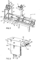
- an automatic case erector and sealer 1 of the invention is notable for its compact size and efficient construction, considering the number of operations which must take place in erecting a case from the flat state, i.e. a so-called "case flat", and gluing it in erected form.
- the magazine of flat boxes is shown at the right side of the erector and sealer 1.
- the spraying and sealing operations for the case erector and sealer 1 are housed in a hood 3, constructed of suitable metal or fibreglass.
- the hood 3 and the magazine 2 rest on a strong frame 4.
- the magazine 2 has, in effect, infinite length because it houses the cases in an edge-supported arrangement (in contrast to vertical hoppers).
- the length of the magazine 2 can be varied to hold, for example, a 1/2 hour supply or many hours supply of flat cases.
- FIGURE 2 illustrates a perspective view of the framework and various components of the case erector and sealer 1.
- the cases are placed on a walking track 5, which advances the horizontal stack of flat cases to the left.
- the frame 4 bearing the walking track 5 can be adjusted to accommodate different case or box lengths by a case-length adjusting handle 6.
- the frame 4 can be adjusted to accommodate various widths of boxes by a case- width adjusting handle 7.
- the walking track 5 is driven by a walking track drive 8, which, by means of an eccentric mechanism, causes a pair,-of the bars of the walking track 5 to rise slightly, move forward slightly and then drop slightly, before returning to their original position. In this way, the cases mounted on the walking track 5 are urged to move to the left slightly, so that there is always a flat case at the front of the magazine 2.
- two case injectors 9 are positioned at the front of the walking track 5. These injectors 9 drive one case upwardly on to pin and dome combinations 11, which are mounted respectively on the inside jaws of a pair of pin erector jaws 10. The bottom edges of the pin erector jaws 10 are curved upwardly to facilitate upward movement of the case on to the pin and dome combinations 11 of the two jaws 10.
- the pin erector jaws 10 are mounted on a vertical wheeled bogey 12.
- the bogey 12 by means of four circular V-grooved castors, can travel upwardly and downwardly on a V-edge vertical erector track 13.
- the pin erector jaws 10 are connected to the bogey 12 by means of parallel motion pivot bars 14.
- the minor flap front tucker 17 is shown in raised position.
- the slanted faces of the minor flap tuckers 16 and 17 cause the minor flaps of the erected case to bend inwardly and subsequently to lie flat in a horizontal position.
- major flap tuckers "18, one mounted on each side of the assembly line cause the major flaps of the erected case to bend inwardly into a partially tucked position.
- the minor flap front tucker 17 being pivotally mounted, pivots downwardly to a horizontal position, to permit a case transit pusher 15 to push the case forwardly (to the left) over a glue head 20.
- the random glue switch sequencing system 19 determines the position of the case on the apparatus and signals the glue head 20 to spray cold adhesive according to a predetermined pattern on to the inside surfaces of the two partially-opened major flaps of the case.
- a case compression platen 24, affixed to a case compression mast 25, is mounted above the compression plate 22 by means of support legs 23. This unit is capable of travelling upwardly and downwardly by means of mast travel wheels 26.
- the platen 24 descends into the interior of the case resting on the compression plate 22 and applies a strong force to the bottommajor and minor flaps of the case, with sprayed cold adhesive therein, thereby rapidly adhering the flaps together.
- a strong force is applied to the top of the compression mast 25 by means of a high compression rocker 27 and compression booster 28.
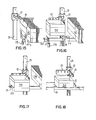
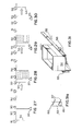
- FIGURE 3 illustrates in perspective a detailed view of the glue head 20.
- the glue head 20 is constructed of a main body 29, which has mounted on its front, a pair of 360 0 rotating nozzle heads 30.
- a cover plate 31 is secured to the rear of the main body 29, which, with the cover plate 31, is affixed on a mounting and supply fin 32 by means of suitable screws and bolts through holes 33.
- the rotating nozzle heads 30 are each constructed with a glue jet and needle combination 34.
- a cross-blower air nozzle 35 is positioned at right-angles and close to the glue jet needle 34.
- Glue for the glue head 20 is supplied through a glue supply port 36.
- Air for the air nozzle 35 is supplied through an air port 37.
- Air required to retract the needle 34 in the glue jet 34 is supplied through an air port 38.
- FIGURE 4 represents, close to actual size, a side elevation view of the glue head 20, described in association with FIGURE 3. It should be noted that the glue head 20, as shown in FIGURE 4, includes an adjusting screw 40 which is located on the rear face of the cover plate 31.
- FIGURE 5 illustrates an end elevation view of the glue head 20, which is again shown close to actual size, as in FIGURE 4.
- the diminutive size of the glue head 20 and the fact that it is reliable in operation are believed to be major innovations and represent substantial advances over much larger and more cumbersome glue heads now used in case-erector and sealing lines and equipment.
- the rotating nozzle heads 30, as shown in FIGURE 5, are positioned so as to spray adhesive in opposite directions to one another, that is, horizontally to either side of the glue head 20.
- the cross-blower air nozzle 35 for each nozzle head 30 is carried in a rotary air nozzle body 39 for each nozzle.
- FIGURE 6 illustrates a cut-away view, larger than actual size, of the glue head 20.
- the rotating nozzle head 30 is shown at the top of the main body 29.
- the manner in which a glue volume adjusting screw 40 fits within the cover plate 31 is readily seen.
- Extending over a substantial length within the body 29 is a needle stem 43.
- this needle stem 43 fits within a nozzle cone 42.
- the needle stem 43 can move slightly upwardly or downwardly as required to enable glue to be ejected around the circumference of the needle 43.
- the needle 43 is pointed and fits within a seat 41 in the cone 42.
- the needle stem 43 is mounted within the body 29 by means of a series of seals comprising needle stem seals 44, a brass seal retainer 45, a seal pressure spring 46, a piston 48 and a piston seal 49.
- An air chamber 47 is located above the piston 48.
- a variable spring 50 (piston return) is positioned below the piston 48 and forces it upwardly. directions.
- the spray pattern 53 assumes a fan shape in each case.
- a further advantage of this arrangement is that the glue head 20 is confined within the partially- closed major flaps 55, so that very little of the glue escapes into the air. Thus coating-out of the glue on surrounding equipment is minimized.
- the direction of travel of the case 54 along the line is shown by an arrow.
- FIGURE 8 illustrates how glue from the glue head 20 is sprayed in a fan-like pattern 53 from the pair of nozzles 34 to apply four generally square areas of adhesive 56 at four locations on the major flaps 55 of the case 54. It is important to note that the glue is applied in the four areas so that a margin is left around the circumferences of these four glue areas 56, to avoid overspray on to the exterior portions of the case or surrounding equipment.
- the timing of glue application is governed by the random glue switch 19 described in detail later in association with FIGURE 21.
- the random glue switch 19 is very versatile and can sense various sizes of box. By sending appropriate electrical signals, it can ensure that glue is properly sprayed at pre- . determined points upon the interior surfaces of the major flaps of cases as they travel along the line.
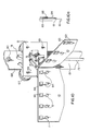
- FIGURE 9 represents a perspective view of the major flap turning and hold-down mechanism 18.
- the mechanism 18 comprises a pair of parallel finger-like prongs 57 extending from an axially-rotatable cylindrical base 58, which is affixed to the frame 4 immediately ahead of the case magazine section.
- the case 54 after being erected by the pin erector jaws 10 and moved over the tuckers 16 and 17, is lowered with its flaps down, so that the two major flaps 55b extend downwardly between the two respective pairs of prongs 57.
- FIGURE 9a The manner in which a major flap 55 extends downwardly between the pair of prongs 57 is illustrated in end elevation view in FIGURE 9a.
- the prongs 57 then rotate clockwise (as seen in FIGURE 9a) through approximately 90° (see FIGURE 9b), whereby the major flap 55 is turned inwardly and upwardly to an almost horizontal position.
- the prongs 57 and base 58 are rotated by an automatic rotating mechanism (not shown) mounted on the back of the plate or frame 4.
- the prongs 57 by gripping the major flaps 55 in effect, hold the case 54 down and permit the pins 64 of the jaws 10 to be pulled upwardly out of the case.
- the box pusher 15 pushes the case 54 along the apparatus over the glue section and off the prongs 57.
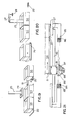
- FIGURE 10 illustrates in detail the construction of the erector jaws 10, the pin and dome combination 11, the wheeled bogey 12 and the parallel-motion side pivot arms 14.
- the entire assembly is capable of travelling upwardly and downwardly on the vertical erector track 13 by means of V-grooved castors 67.
- These castors 67 are rotationally mounted on the bogey 12 by means of four castor axles 69.
- the castors 67 travel in pairs upwardly and downwardly on the pair of V-faced tracks 68. Upward motion of the bogey 12 is stopped at a predetermined point by a pivot stop 80.
- the pair of erector jaws 10 operate in clam-shell manner about a pivot point from a position where they are proximate and parallel to one another to a position where they are at right-angles to one another (as shown in FIGURE 10).
- Mounted in linear series on the two respective interior faces of the pair of erector jaws 10 are a plurality of the pin and dome combinations 11. While the number of pin and dome combinations 11 can be varied as required, as shown in FIGURE 10, five pin and dome combinations 11 are preferably positioned in a line on the main erector jaw 10, shown at the left side of FIGURE 10, while three pin and dome combinations 11 are preferably positioned in a line on the right erector jaw 10.
- the two pin and dome combinations 11 mounted in the region of the erector jaw 10 remote from the pivot point have pairs of pins, while the three combinations 11 nearer to the pivot point have single pins.
- a pair of pins rather than a single pin, provides better gripping action on a case which has been opened by means of the clam-shell-like action of the pair of erector jaws 10.
- the two sides of the opened case not held by the pair of erector jaws 10 create a bending moment on the two erector jaws 10 and this moment is better handled by having pairs of pins located at the remote wings of the erector jaws 10.
- Single pins are used in the interior where the grip need not be as strong.
- Domes 61 are preferred because they guide the upper edges of the flat case easily and smoothly on to the sharp points of the needles or pins 64.
- the pins 64 are mounted in pin-retaining blocks 63, which are held on the erector jaws 10 at desired locations by retaining screws 65.
- the sharpened points of the pins 64 are hardened by known metal-hardening techniques and are carefully polished to ensure that they easily penetrate the edges of a corrugated cardboard box, without creating a substantial amount of resistance. This ensures trouble- free operation.
- Relative orientation of the erector jaws 10 and the wheeled bogey 12 is maintained by means of a set of four parallel-motion side pivot arms 14. These arms 14 permit the erector jaws 10 to be moved from left to right and in reverse, as seen in FIGURE 10, and thus permit the erected case to be opened from a closed flat position and moved from right to left along the case erector and gluing line.
- the action of the pivot arms 14 is controlled by side-motion actuation dogs 71 which are located on the reverse side of the bogey 12. These dogs 71 are controlled by an actuation bar 72, which moves upwardly and downwardly.
- FIGURE 10a illustrates a detailed side view of the relative orientation of a pin 64 with its dome 61, as mounted on the jaw plate 10.
- the pin 64 can be removed for sharpening or replacement and is secured in the pin block 63 by means of a pin-holding screw 66.
- FIGURE 11 illustrates in enlarged view, the manner in which the edge of a corrugated Kraft cardboard piece 73 is guided by means of a dome 61 on to the sharpened tip of a needle 62.
- a dome 61 To enable efficient operation of the case-erecting line, at high speed, it is extremely important that the edge of the corrugated board 73 of the flat case is guided precisely on to the sharpened tip of the needle 62. This is accomplished by the dome 61.
- FIGURE 12 illustrates in enlarged and exaggerated end elevation view the manner in which the alternating positioning of the domes 61 and pins 62, on the respective parallel opposing erector jaw faces 10, forces the edge of the corrugated cardboard 73 to be guided on to the tips of the pins 62 such that the edge of the cardboard 73 assumes a sine-wave pattern.
- This sine-wave pattern in combination with the action of the plurality of domes 61, ensures that the edge of the corrugated cardboard 73 is injected on to the sharp tips of all of the plurality of pins 62. This ensures that the cardboard edge does not miss the hardened points or is skewered only by some of the pins.
- FIGURE 12 It can be seen in FIGURE 12 that the alternating dome and pin design permits various thicknesses of cardboard 73 to be handled by the pin 62 and dome 61 combination. This is done by the clearance 74 between the pin 62 and the face of the opposite erector jaw 10.
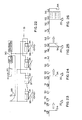
- FIGURE 13 reflects the prior art and illustrates the number of steps required in order to glue a case using conventional case-gluing equipment. Using such equipment, it is necessary for the case to travel through four case (box) lengths before the major and minor flaps of the case can be compression sealed. Furthermore, the process is energy-consumptive, not only because the case must pass through four case lengths in order to be glued, but also the major flaps of the case must be folded, completely opened and closed during the sequence.
- FIGURE 14 shows the marked contrast in distance, time and technique possible with the case gluing system of this invention, when compared to the conventional method illustrated in FIGURE 13.
- An important distinction is that the major flaps of the case, in the process of the invention, need not be fully opened and closed in order to be glued. This is because of the unprecedented diminutive size of the glue head 20 (which heretofore was not thought possible), and the extremely efficient glue-spraying pattern which can be created by this glue head 20.
- FIGURES 15 to 20 The method whereby a flat case is taken from a magazine, opened into a rectangular case shape, folded to tuck the underlying minor and major flaps of the case, glue-sprayed and then compression sealed is illustrated sequentially in FIGURES 15 to 20.
- the walker bar 5 continually moves the flat cases (blanks) so that the front case (the left-most case) abuts the case injector 9.
- an injector cylinder 75 upon automatic command, this injects a single flat case upwardly into the space between the two parallel erector jaws 10 and on to the pins mounted between the two jaw faces (as seen in enlarged detail in FIGURE 12).
- the pair of erector jaws 10 by means of the parallel motion pivot bars 14, move the case or box and themselves away from the magazine 2 of the cases 76 and, at the same time, they open to a point where they are at right-angles to one another.
- the case is simultaneously moved away from the magazine of flat cases 76 and is opened into a rectangular orientation (when viewed from above or below) to a point where the opened case 54 is positioned immediately above the minor flap tuckers 16 and 17.
- the fold-down front minor flap tucker 17 is raised upon command by means of an air cylinder 78 and, subsequently, when the case 54 is moved down the line, the air cylinder 78 operates to pull the flap tucker 17 downwardly to a horizontal position, thereby enabling the case 54 to pass over it (see FIGURE 17).
- the case 54 As seen in FIGURE 17, the case 54, by means of the bogey 12, which travels downwardly on the vertical erector track 13, descends upon the minor flap tuckers 16 and 17, so as to fold the two minor flaps of the case 54 inwardly and upwardly. Then, as seen in FIGURE 18, the pair of rotatable major flap tuckers 18, with the prongs 57, grip the major flaps 55 on either side of the case 54. The two pairs of prongs 57 rotate and tuck the two major flaps 55 of the case inwardly and slightly upwardly to a point where the major flaps are within approximately 30 degrees of being completely folded horizontally against the bottom of the case 54.
- the glue head 20 is shown as spraying adhesive in a fan-like pattern laterally to either side from two nozzles.
- adhesive is not sprayed by the glue head 20 until it is completely housed within the major flaps 55 of the case 54. This ensures that adhesive will not be sprayed at large on to surrounding equipment.
- Timing of the spray of adhesive from the glue head 20 on to the interior surfaces of the major and minor flaps is determined by the random glue switch 19, which by means of sensors detects the leading edge of the case 54, permits it to proceed along the line a small further distance, and then signals the glue head 20 and its air supply to spray adhesive inside the two major flaps.
- the preferred adhesive pattern is four separate rectangular patches of glue on the major and minor flaps, as illustrated and discussed previously in association with FIGURE 8.
- the two major flaps 55 of the case 54 are closed to a horizontal position by pushing the case 54 further to a position where it rests on the compression plate 22. At this point, the case 54 is directly under the compression platen 24. Also, the case 54 is held between two parallel side mounted endless alignment belts 21 (see FIGURE 2).
- the compression platen 24, by means of a vertical ram 25, is moved downwardly in the case 54 to a point where it touches the upper surfaces of the two minor bottom flaps.
- high pressure is applied to the top of the ram 25 by means of the booster cylinder 28, which acts through the rocker arm 27. This high pressure forces the interfaces of the major and minor flaps of the case 54 tightly together and ensures that the flaps are glued securely together.
- the ram 25 moves upwardly to a point where the compression platen 24 is withdrawn above the upper regions of the case 54.
- the case 54 is then moved further down the line to a point where it is pulled away by means of an outfeed belt 79.
- the case 54 can be filled with appropriate consumer items, such as cans or bottles.
- FIGURE 21 illustrates in side elevation view a detail of the random glue switch sequencer 19, which automatically determines the leading and trailing edges of the case 54 and regulates the turning on and off of the air and glue supplies to the glue head 20.
- a wheeled bogey 81 rides on a central track 82 and is located and oriented with the box pusher 15.
- a front air switch 83 and a front glue switch 84 are mounted on a carrier connected to the case magazine rack 76.
- a back blowing air switch 85 and a back glue switch 86 are mounted on a second support affixed to the compression plate 22.
- the wheeled bogey 81 carries a glue carrier 87 which has thereon a glue cam 88 and an air cam 89.
- the leading edge of the magazine location is determined by the adjustment position of the box length adjusting handle 6. This determines the location of the front air switch 83 and the front glue switch 84.
- the distance between the front switches 83 and 84 and the back switches 85 and 86 is related to the length of the case 54.
- the air cam 89 and glue cam 88 which move in unison with the box pusher 15, first contact respectively the switches 83 and 84, which in turn, by electrical signals, cause the glue head 20 to spray adhesive on the flaps 55 of the case 54.
- the length of adhesive spray time is proportionately determined by the length of the glue cam 88 and the air cam 89. A longer length means a longer spray time, and vice versa.
- the glue cam carrier 87 during its travel along the track 82, after contacting the switches 83 and 84, covers a distance where the cams contact no switches. Then, after travelling over this region, the carrier 87 approaches the compression plate 22, whereupon the cams 88 and 89 contact the back blowing air switch 85 and the back glue switch 86. This contact causes a second application of adhesive by the glue head 20 to a second area of the flaps 55 (see FIGURE 8).
- the glue spray actuation mechanism starts prior to the air flow and ceases prior to the air being turned off, which assists in keeping the glue head 20 clean and functioning efficiently.
- the carrier 87 illustrated in FIGURE 21 shows different lengths of cams above one another.
- the carrier 87 can be adjusted upwardly or downwardly in order to expose various lengths of cams to the air and glue switches, thereby regulating as required the length of the adhesive spray time.
- the cam length can be varied by constructing the cams in two parallel strips which can be moved relative to one another, thereby in effect providing a longer or shorter cam length, as required.
- the switches 83, 84, 85 and 86 can be inactivated, or the carrier 82 can be drawn back, on return of the carrier 87 to its original position, thereby preventing the spraying of adhesive from the glue head 20 when it is not wanted.
- FIGURES 22 to 30 illustrate the construction and sequential operation of an alternative type of random glue switch sequencer 19.
- this other form of random glue switch sequencer 19 comprises four electrical switches 91, 92, 93 and 94, arranged in a line parallel and adjacent to the path travelled by a case to be glued (indicated by the two double-headed arrows).
- the four switches have four respective contact sensors 95, 96, 97 and 98.
- Each switch is connected in series to an electrical power supply 99 according to the circuit diagram shown in FIGURE 22.
- the switches 91 to 94 are also connected to a solenoid-actuated air valve 90 which in turn delivers compressed air to the glue head 20 and causes it to spray glue as required.
- the case 54 As may be seen in sequence in FIGURES 23 to 30, the case 54, as it travels along the line as indicated by the arrow, first contacts the switch 91 (FIGURE 23) and then the switch 92. Contact with these two switches does not activate the solenoid-actuated air valve 90 and hence no glue is sprayed on the major flaps of the case 54. However, when the case 54 advances along the line to the point where it contacts the switch 93 (FIGURE 25), then the valve 90 is actuated and the glue head 20 commences to spray glue on the major flaps of the case 54 (the second major flap and glue nozzle are not shown for simplicity of illustration). Glue continues to be sprayed on the case 54 until the switch 94 is contacted. Then the air valve is turned off and glue spraying stops.
- the case 54 proceeds further along the line until its end loses contact with the switch 91 (FIGURE 27). This activates the valve 90 a second time and the glue head 20 commences to spray glue on the major flap of the case 54 at a second location (see the pattern shown in FIGURE 8).
- the glue head 20 continues to spray glue on the major flap (see FIGURE 28) until the rear corner of the case 54 advances to the point where it loses contact with the switch 92. This de-activates the air valve 90 and the glue head 20 stops spraying glue. The case 54 then proceeds along the line, ultimately losing contact with the switches 93 and 94 as well (see FIGURES 29 and 30). These two switches activate the air valve 90 only when contacted by the leading edge of the case 54 and have no function when released by the rear edge of the case 54.
- This embodiment of the random glue switch sequencer 19 requires a between-case resetting mechanism (not shown) or a one-case length space between cases so that the sensors 85, 86, 87 and 88 can return to their original positions after being triggered.
- the contact sensors 95, 96, 97 and 98 have sufficient length to function properly, even though there may be significant variations in the widths of the cases 54 proceeding in series along the line. To accommodate large differences in case widths, however, such as when the line is being converted from handling one width of case to handling another width of case, the position of the overall random glue switch sequencer 19 can be moved inwardly or outwardly, as required. Further, the relative lengths and distances between the glue-sprayed areas can be adjusted as required by varying the distances between the four switches 91, 92, 93 and 94.
- FIGURE 31 illustrates in perspective view an alternative apparatus for holding the case 54 downwardly by means of a pair of transit bars 155 positioned over the minor front flap tucker 17.
- the case 54 is gripped by means of hold-down strips 157, mounted on the interior sides of the two transit bars 155.
- hold-down strips 157 mounted on the interior sides of the two transit bars 155.
- This force attempts to drive the case54 upwardly, which is detrimental to proper functioning of the line.
- This force can be resisted by means of the hold-down strips 157, which, in association with the retaining or transit bars 155, are mounted in a self-correcting manner about a pivot point 158.
- the retaining transit bars 155, together with the hold-down strips 157 can be moved inwardly or outwardly in a lateral direction from each side of the case 54. This can be done by actuator bars or some other acceptable and known technique.
- one of the major flaps 55 is shown in a vertically downward orientation. This is for illustrative purposes only. In operation, the two major flaps are bent inwardly by the fingers of the major flap tuckers and the hold-downs 155 which pivotally rotate inwardly and upwardly as required.
- FIGURE 31a shows in detail the way in which the pair of hold-down strips 157 are mounted within the retaining bar 155 by means of rubber retaining rings 160.
- a mechanical system has been devised which takes advantage of this discovery and puts it to practical use.
- the system is basically designed for gluing together the flaps of boxes, cartons or cases erected from the flat state and used as packaging for articles such as cans or bottles.
- the system compresses tightly together the bottom of a partially-assembled corrugated cardboard box, including the flaps, by using a primary compression plate system with a secondary booster system.
- the key to the invention is the discovery and recognition that it is possible to adhere two pieces of pressed fibrous material together, such as corrugated cardboard, using a cold-cure adhesive, in a matter of only 0.25 to 1.5 seconds by using a combination of high pressure and a thinly-spread atomized pattern of adhesive discretely broadcast over one or both of the interface surfaces to be glued together in a parallel manner. While a pressure within a broad range may suffice, it has been found that a pressure in the range from 1.4 to 11.2 kg/cm , (namely 20 to 160 lbs per sq in) gives good results.
- the items in erected form are around 25 to 75 cm (10 - 30 inches) in depth. Furthermore, the boxes, cases or cartons are travelling along the line at a rate of 20 to 40 boxes per minute. These rates allow only short manipulation times for each box, ranging from 16 to 3 seconds.
- the high pressure applicator in order to accomplish an operation, such as the sealing of the bottom flaps of a box, it is necessary for the high pressure applicator to descend rapidly into the interior of the box for a distance of at least 25 to 75 cm (10 to 30 inches) to a position near the bottom of the box and then, at the end of the stroke, to apply a pressure of 1.4 to 11.2 kg/cm 2 (20 to 160 lbs per sq in) to the bottom of the box.
- the pressure applied will vary according to process conditions and requirements. These conditions present a difficult operational problem, because the pressure applicator not only has to travel at substantial speeds, but it must be heavy and strong enough (which creates an unwanted high inertia coefficient) to generate a substantial force at the end of each stroke.
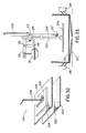
- a secondary booster system which operates in the following manner. After the lightweight pressure applicator descends rapidly into the interior of the corrugated box by 25 to 75 cm (10 to 30 inches) as required, a secondary pressure booster system comes into play and applies 1.4 to 11.2 kg/cm 2 (20 to 160 lbs per sq in) of pressure for the last 3mm (1/8 inch) stroke of the pressure applicator. This system is described in more detail below in association with FIGURES 32 to 34 of the accompanying drawings.
- FIGURE 32 two parallel horizontal pieces of corrugated cardboard 201 and 202 are shown separated from one another.
- An atomized dot-like pattern of discrete particles of liquid or emulsified cold-cure adhesive 203 has been applied over the top surface of the bottom piece of cardboard 202.
- the adhesive 203 can be applied by any suitable adhesive applicator nozzle. However, it is highly important that the adhesive is sprayed over the surface in a thin pattern of tiny discrete particles and not as large drops or globules. If required or desirable, adhesive can also be sprayed on the under surface of the top piece of cardboard 201.
- a pressure applicator 204 Positioned above the upper piece of cardboard 201 is a pressure applicator 204, which consists of a horizontal broad and flat compression platen 205 constructed of steel or other suitably strong material.
- the platen 205 is controlled by a vertical ram bar 206, which travels upwardly or downwardly through a vertical stroke, as required.
- the platen 205 is reinforced by a support 207 at the point where it meets the ram bar 206.
- FIGURE 33 depicts, in side elevation view, the position of the applicator 204 before it descends to the bottom of its travel to press the cardboard pieces 201 and 202 together in parallel fashion.
- the upward and downward movement of the bar 206 is controlled by an air cylinder 208, which operates at 4.2 to 7.0 kg/cm 2 (60 to 100 lbs per sq in) pressure and extends a rod 209 from an upper position, as shown in FIGURE 33, to a lower position as shown in FIGURE 34.
- the rod 209 is connected to the bar 206 by an attachment 210.
- the air cylinder 208 is capable of moving the platen 205 from its top position (as shown in FIGURE 33) to its bottom position, and in reverse, in rapid succession. This action enables the platen 205 to be moved upwardly and downwardly into and out of the interiors of corrugated cardboard boxes travelling along lines which erect and assemble 20 to 30 boxes per minute.
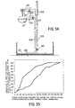
- the final pressure of the order of 1.4 to 11.2 k g/cm 2 (20 to 160 lbs per sq in), over the last 3mm (1/8 inch) of travel of the applicator 204, is provided by a high-compression hammer 210 and a high-compression booster cylinder 211 in combination.
- a booster force is applied to the top of the ram bar 206 by the hammer 210 which is activated by the booster cylinder 211.
- the booster hammer 210 pivots about a horizontal pivot 212 or similar device.
- the cylinder 211 automatically becomes activated at the bottom.of the stroke of the pressure applicator 204 by means of a ram bar hammer advance knob 213 contacting an advance crank 214 (see FIGURE 34) to provide a strong solid force generating 1.4 to 11.2 kg/cm 2 (20 to 160 lbs per sq in), to the top of the bar 206.
- the action.of the hammer 210 on the top of the bar 206 causes the applicator 204 to travel approximately 3mm (1/8 inch) further at the bottom of its stroke, thereby firmly pressing together the cardboard pieces 201 and 202 and the discrete interface of cold-cure adhesive.
- the booster pressure can typically be 1/2 to 2 seconds in duration, or longer or shorter, as required to meet process requirements.
- the hammer 210 at the bottom of the stroke by means of contact of the knob 213 with the crank 214, rotates slightly to the right about the pivot 215, so that its right end is over the bar 206. While it is not shown, the air cylinder 208, the air cylinder 211 and the pivot 215 are secured to a frame for solid support. The sides of this case can be held by a suitable hold-down mechanism such as mechanical flap- clutching fingers, side clamps or transit bars 216, as shown.
- liquid polyvinyl acetate cold-cure resin adhesive is satisfactory for the purposes of this invention. Maximum adhesion strength, following initial adhesion, is obtained within the next 5 to 10 seconds.
- the adhesion provided by a liquid cold-cure adhesive is substantially superior to a hot-melt adhesive system and, unlike a hot-melt adhesive system, is so strong upon ultimate cure that the cardboard itself will part, before the adhesive will part.
- a distinct advantage of the secondary high pressure booster step is that it saves energy and cuts down on equipment costs by eliminating heavy equipment capable of applying and transmitting high pressure throughout the entire operation cycle. High pressure is applied only at the last critical portion of the stroke cycle of the pressure applicator 204 and thus enables a lighter construction of apparatus to be used.
- a compressed air system is believed to be the preferred system for driving the various components of the apparatus.
- a hydraulic oil system is not satisfactory for line speeds as described, because such a system is too slow.
- air is clean whereas oil tends to leak from time to time and provides a hygiene problem which is not accepted in many packaging environments such as food packaging.
- FIGURE 35 which depicts in graphical manner the behaviour of cold-cure adhesive sprayed on to the interface of two sheets of paper
- the upper line displays the amount of fibre tear using a light dense spray of droplets
- the lower line displays the amount of fibre tear using a heavy atomised spray of droplets.
- the adhesive used in the tests giving rise to the graphical data depicted in FIGURE 35 is available under the trade mark RESYN 33-1583 (formerly 72-1142) and has the following characteristics:
- the graph is based on 1.5 seconds of compression time. Beyond this time, further compression does not appear to influence adhesive droplet penetration. Therefore, adhesive curing time starts no later than 1.5 seconds. Fibre Tear Factor vs. Time
- Fibre tear testing was calculated 1.0 second after 1.5 seconds of compression time.
- the graph displays the correct percentage of fibre tear for 1.5 seconds of compression.
- Reactivation of dried adhesive using forms of water application has also been found to result in usable bonding when subjected to high compression techniques according to the invention.
Landscapes
- Making Paper Articles (AREA)
- Package Closures (AREA)
Priority Applications (1)
| Application Number | Priority Date | Filing Date | Title |
|---|---|---|---|
| AT82301970T ATE30535T1 (de) | 1981-04-17 | 1982-04-16 | Behaelterformer und klebemaschine, die einen schnell und kalt erhaertenden klebstoff verwendet. |
Applications Claiming Priority (4)
| Application Number | Priority Date | Filing Date | Title |
|---|---|---|---|
| US25509581A | 1981-04-17 | 1981-04-17 | |
| US255095 | 1981-04-17 | ||
| US06/255,336 US4375383A (en) | 1981-04-17 | 1981-04-17 | High speed cold adhesive curing process and apparatus therefor |
| US255336 | 1994-06-07 |
Publications (3)
| Publication Number | Publication Date |
|---|---|
| EP0063484A2 true EP0063484A2 (de) | 1982-10-27 |
| EP0063484A3 EP0063484A3 (en) | 1983-08-24 |
| EP0063484B1 EP0063484B1 (de) | 1987-11-04 |
Family
ID=26944428
Family Applications (1)
| Application Number | Title | Priority Date | Filing Date |
|---|---|---|---|
| EP82301970A Expired EP0063484B1 (de) | 1981-04-17 | 1982-04-16 | Behälterformer und Klebemaschine, die einen schnell und kalt erhärtenden Klebstoff verwendet |
Country Status (2)
| Country | Link |
|---|---|
| EP (1) | EP0063484B1 (de) |
| DE (1) | DE3277572D1 (de) |
Cited By (8)
| Publication number | Priority date | Publication date | Assignee | Title |
|---|---|---|---|---|
| EP1426172A3 (de) * | 2002-12-06 | 2007-07-25 | Robert Bosch Gmbh | Vorrichtung zum Entnehmen und Aufrichten eines Faltschachtelzuschnitts |
| ES2422956R1 (es) * | 2012-03-09 | 2013-09-23 | Olmos Telesforo Gonzalez | Unidad de inyectado de cola fria |
| CN108582871A (zh) * | 2018-04-10 | 2018-09-28 | 东莞市欣豪印刷包装有限公司 | 一种彩盒半自动高效成型机 |
| BE1025786B1 (nl) * | 2017-12-15 | 2019-07-15 | Pattyn Packing Lines Nv | Verbeterde inrichting voor het vormen van een doos |
| CN112549646A (zh) * | 2021-01-02 | 2021-03-26 | 黄瑞湖 | 一种包装纸箱加工用的移动粘箱机 |
| CN113479402A (zh) * | 2021-06-18 | 2021-10-08 | 武汉人天包装自动化技术股份有限公司 | 一种立式高速开箱机 |
| CN113479401A (zh) * | 2021-06-18 | 2021-10-08 | 武汉人天包装自动化技术股份有限公司 | 一种立式高速开箱机的开箱方法 |
| CN113978026A (zh) * | 2021-11-23 | 2022-01-28 | 高友军 | 一种瓦楞纸成箱设备 |
Family Cites Families (5)
| Publication number | Priority date | Publication date | Assignee | Title |
|---|---|---|---|---|
| US2577205A (en) * | 1946-11-20 | 1951-12-04 | Owens Corning Fiberglass Corp | Method of producing a fabric construction for reinforcing plastics and product |
| CH300320A (de) * | 1951-05-15 | 1954-07-31 | E Abel Heinrich | Vorrichtung zum Herstellen eines textilen Stoffes aus mindestens zwei Stoffbahnen, welche mittels einer Klebemittelmasse zusammengeklebt werden. |
| GB984038A (en) * | 1963-03-08 | 1965-02-24 | Dennis Killen | Improvements relating to the combining of continuous webs together |
| DE2500568B2 (de) * | 1975-01-09 | 1978-04-20 | Carl Edelmann Gmbh, 7920 Heidenheim | Verfahren und Maschine zum Aufrichten von flachliegenden Zuschnitten zur Bildung von Kartonpackungen |
| GB2052380B (en) * | 1979-06-29 | 1983-04-07 | Chromatex Inc | Laminated polypropylene fabric |
-
1982
- 1982-04-16 DE DE8282301970T patent/DE3277572D1/de not_active Expired
- 1982-04-16 EP EP82301970A patent/EP0063484B1/de not_active Expired
Cited By (9)
| Publication number | Priority date | Publication date | Assignee | Title |
|---|---|---|---|---|
| EP1426172A3 (de) * | 2002-12-06 | 2007-07-25 | Robert Bosch Gmbh | Vorrichtung zum Entnehmen und Aufrichten eines Faltschachtelzuschnitts |
| ES2422956R1 (es) * | 2012-03-09 | 2013-09-23 | Olmos Telesforo Gonzalez | Unidad de inyectado de cola fria |
| BE1025786B1 (nl) * | 2017-12-15 | 2019-07-15 | Pattyn Packing Lines Nv | Verbeterde inrichting voor het vormen van een doos |
| CN108582871A (zh) * | 2018-04-10 | 2018-09-28 | 东莞市欣豪印刷包装有限公司 | 一种彩盒半自动高效成型机 |
| CN112549646A (zh) * | 2021-01-02 | 2021-03-26 | 黄瑞湖 | 一种包装纸箱加工用的移动粘箱机 |
| CN113479402A (zh) * | 2021-06-18 | 2021-10-08 | 武汉人天包装自动化技术股份有限公司 | 一种立式高速开箱机 |
| CN113479401A (zh) * | 2021-06-18 | 2021-10-08 | 武汉人天包装自动化技术股份有限公司 | 一种立式高速开箱机的开箱方法 |
| CN113479402B (zh) * | 2021-06-18 | 2023-02-14 | 武汉人天包装自动化技术股份有限公司 | 一种立式高速开箱机 |
| CN113978026A (zh) * | 2021-11-23 | 2022-01-28 | 高友军 | 一种瓦楞纸成箱设备 |
Also Published As
| Publication number | Publication date |
|---|---|
| EP0063484A3 (en) | 1983-08-24 |
| EP0063484B1 (de) | 1987-11-04 |
| DE3277572D1 (en) | 1987-12-10 |
Similar Documents
| Publication | Publication Date | Title |
|---|---|---|
| US4553954A (en) | Automatic case erector and sealer | |
| US4578054A (en) | Carton erection and sealing apparatus | |
| US8177698B2 (en) | Apparatus and method for forming a container having an enhanced corner support structure | |
| US3633470A (en) | Package feeder apparatus | |
| EP0063484B1 (de) | Behälterformer und Klebemaschine, die einen schnell und kalt erhärtenden Klebstoff verwendet | |
| US4331434A (en) | Method and apparatus for forming a container for liquids | |
| US4289491A (en) | Apparatus for adhesively bonding a carton | |
| GB2093762A (en) | Forming and/or closing cartons | |
| EP0766621A4 (de) | Vorrichtung und verfahren zum aufnehmen und aufrichten von kartonzuschnitten | |
| US4817931A (en) | Folded leaflet and method and apparatus for making same | |
| US4531931A (en) | Apparatus for opening up folded boxes | |
| GB2023536A (en) | Process and apparatus for erecting and sealing a collapsedcarton | |
| US4832675A (en) | Tray forming apparatus | |
| EP0333800B1 (de) | Vorrichtung zum anbringen von tragegriffen auf schachteln | |
| US4331435A (en) | Method and apparatus for erecting a carton | |
| US4256025A (en) | Apparatus for forming a hinged carton | |
| US4767390A (en) | Apparatus for and method of applying handle to carton closure flap | |
| US4310323A (en) | Method of manufacture of H-divider containers | |
| US4378080A (en) | Fluid velocity attenuating nozzle | |
| US4311476A (en) | Method and apparatus for forming a container for liquids | |
| HU906555D0 (en) | Apparatus for shaping cylindrical cardboard lamina | |
| GB2106033A (en) | Method and apparatus for binding sheets of paper together | |
| US3511138A (en) | Box erecting devices for reducing the effect of stringing out of adhesives | |
| US3531914A (en) | Packaging machine | |
| US2696612A (en) | Boxmaking machine |
Legal Events
| Date | Code | Title | Description |
|---|---|---|---|
| PUAI | Public reference made under article 153(3) epc to a published international application that has entered the european phase |
Free format text: ORIGINAL CODE: 0009012 |
|
| AK | Designated contracting states |
Designated state(s): AT BE CH DE FR GB IT LI LU NL SE |
|
| PUAL | Search report despatched |
Free format text: ORIGINAL CODE: 0009013 |
|
| RHK1 | Main classification (correction) |
Ipc: B31B 5/74 |
|
| AK | Designated contracting states |
Designated state(s): AT BE CH DE FR GB IT LI LU NL SE |
|
| 17P | Request for examination filed |
Effective date: 19840206 |
|
| GRAA | (expected) grant |
Free format text: ORIGINAL CODE: 0009210 |
|
| AK | Designated contracting states |
Kind code of ref document: B1 Designated state(s): AT BE CH DE FR GB IT LI LU NL SE |
|
| PG25 | Lapsed in a contracting state [announced via postgrant information from national office to epo] |
Ref country code: LI Effective date: 19871104 Ref country code: IT Free format text: LAPSE BECAUSE OF FAILURE TO SUBMIT A TRANSLATION OF THE DESCRIPTION OR TO PAY THE FEE WITHIN THE PRESCRIBED TIME-LIMIT;WARNING: LAPSES OF ITALIAN PATENTS WITH EFFECTIVE DATE BEFORE 2007 MAY HAVE OCCURRED AT ANY TIME BEFORE 2007. THE CORRECT EFFECTIVE DATE MAY BE DIFFERENT FROM THE ONE RECORDED. Effective date: 19871104 Ref country code: CH Effective date: 19871104 Ref country code: BE Effective date: 19871104 Ref country code: AT Effective date: 19871104 |
|
| REF | Corresponds to: |
Ref document number: 30535 Country of ref document: AT Date of ref document: 19871115 Kind code of ref document: T |
|
| PG25 | Lapsed in a contracting state [announced via postgrant information from national office to epo] |
Ref country code: SE Effective date: 19871130 |
|
| REF | Corresponds to: |
Ref document number: 3277572 Country of ref document: DE Date of ref document: 19871210 |
|
| ET | Fr: translation filed | ||
| REG | Reference to a national code |
Ref country code: CH Ref legal event code: PL |
|
| PG25 | Lapsed in a contracting state [announced via postgrant information from national office to epo] |
Ref country code: LU Free format text: LAPSE BECAUSE OF NON-PAYMENT OF DUE FEES Effective date: 19880430 |
|
| PLBE | No opposition filed within time limit |
Free format text: ORIGINAL CODE: 0009261 |
|
| STAA | Information on the status of an ep patent application or granted ep patent |
Free format text: STATUS: NO OPPOSITION FILED WITHIN TIME LIMIT |
|
| 26N | No opposition filed | ||
| PGFP | Annual fee paid to national office [announced via postgrant information from national office to epo] |
Ref country code: FR Payment date: 19950330 Year of fee payment: 14 |
|
| PGFP | Annual fee paid to national office [announced via postgrant information from national office to epo] |
Ref country code: GB Payment date: 19950406 Year of fee payment: 14 |
|
| PGFP | Annual fee paid to national office [announced via postgrant information from national office to epo] |
Ref country code: NL Payment date: 19950430 Year of fee payment: 14 |
|
| PGFP | Annual fee paid to national office [announced via postgrant information from national office to epo] |
Ref country code: DE Payment date: 19950614 Year of fee payment: 14 |
|
| PG25 | Lapsed in a contracting state [announced via postgrant information from national office to epo] |
Ref country code: GB Effective date: 19960416 |
|
| PG25 | Lapsed in a contracting state [announced via postgrant information from national office to epo] |
Ref country code: NL Effective date: 19961101 |
|
| GBPC | Gb: european patent ceased through non-payment of renewal fee |
Effective date: 19960416 |
|
| PG25 | Lapsed in a contracting state [announced via postgrant information from national office to epo] |
Ref country code: FR Effective date: 19961227 |
|
| PG25 | Lapsed in a contracting state [announced via postgrant information from national office to epo] |
Ref country code: DE Effective date: 19970101 |
|
| NLV4 | Nl: lapsed or anulled due to non-payment of the annual fee |
Effective date: 19961101 |
|
| REG | Reference to a national code |
Ref country code: FR Ref legal event code: ST |