EP0063306B1 - Compteur électronique employant l'échange de charge d'un condensateur - Google Patents
Compteur électronique employant l'échange de charge d'un condensateur Download PDFInfo
- Publication number
- EP0063306B1 EP0063306B1 EP82102915A EP82102915A EP0063306B1 EP 0063306 B1 EP0063306 B1 EP 0063306B1 EP 82102915 A EP82102915 A EP 82102915A EP 82102915 A EP82102915 A EP 82102915A EP 0063306 B1 EP0063306 B1 EP 0063306B1
- Authority
- EP
- European Patent Office
- Prior art keywords
- output
- integrator
- signal
- limit value
- input
- Prior art date
- Legal status (The legal status is an assumption and is not a legal conclusion. Google has not performed a legal analysis and makes no representation as to the accuracy of the status listed.)
- Expired
Links
- 239000003990 capacitor Substances 0.000 title claims abstract description 10
- 230000005611 electricity Effects 0.000 claims abstract description 12
- 238000000034 method Methods 0.000 claims abstract description 12
- 238000005265 energy consumption Methods 0.000 claims abstract description 7
- 230000008859 change Effects 0.000 description 6
- 230000000052 comparative effect Effects 0.000 description 3
- 230000000694 effects Effects 0.000 description 3
- 230000008569 process Effects 0.000 description 3
- 230000000630 rising effect Effects 0.000 description 3
- 230000007423 decrease Effects 0.000 description 2
- 238000010586 diagram Methods 0.000 description 2
- 238000005259 measurement Methods 0.000 description 2
- 238000006243 chemical reaction Methods 0.000 description 1
- 230000006870 function Effects 0.000 description 1
- 230000010354 integration Effects 0.000 description 1
- 230000009467 reduction Effects 0.000 description 1
- 230000001960 triggered effect Effects 0.000 description 1
- 238000011144 upstream manufacturing Methods 0.000 description 1
Images
Classifications
-
- G—PHYSICS
- G01—MEASURING; TESTING
- G01R—MEASURING ELECTRIC VARIABLES; MEASURING MAGNETIC VARIABLES
- G01R21/00—Arrangements for measuring electric power or power factor
Definitions
- the invention relates to an electronic electricity meter operating according to the capacitor recharging method for detecting the energy consumption from at least one phase of an electrical network, in which the phase is assigned a multiplier, to which the current and voltage proportional signals are supplied on the input side and the power-proportional output signals of all multipliers are added to form a sum signal are, which is a quantizer consisting of an integrator and a downstream, an upper and a lower limit value limiting element for forming a pulse train with power-proportional frequency is supplied, the sum signal is reversed each time a limit value is reached, so that the output signal of the integrator between represents the signal, which is essentially triangular in shape, and the pulse train feeds a counter for energy consumption via a frequency divider.
- Such an electricity meter is known from the magazine "Technisches Messen atm", 1978, number 11, pages 407 to 411 in the form of a three-phase meter or from DE-OS-27 47 385, Fig. 1 and associated text, in the form of a single-phase alternating current meter
- the product signal resulting from the multiplication of related current and voltage proportional signals is integrated in a quantizer and processed so that a pulse train with power proportional frequency is produced at the output of the quantizer.
- the charge compensation method can also be used in principle.
- the low maximum pulse frequency in the capacitor recharging process has a disadvantageous effect for control purposes in the context of power control loops, since the information about the instantaneous power lies in the time interval between two successive pulses of the pulse train and thus is not a current one for the fast time period between two pulses Power control usable statement about the actual power value is available.
- the invention has for its object to develop an electricity meter of the type mentioned in such a way that in addition to the pulse train emitted by the quantizer, a further pulse train with a power-proportional but considerably higher frequency is available at a measurement output.
- a pulse multiplication circuit which has a voltage comparator for comparing the output signal of the integrator with a plurality of threshold voltages lying between the limit values and which are equidistant from one another with respect to the voltage level, the voltage comparator then in each case providing an output signal, when the integrator output signal reaches one of the threshold voltages.
- the number of additional pulses corresponds to the number of threshold voltages lying between the limit values.
- the voltage comparator can consist of several individual comparators, in each of which a threshold value voltage that differs from all other threshold value voltages is compared with the output signal of the integrator.
- the additional pulses arise both during the rise time of the essentially triangular-shaped output signal of the integrator and during the fall time of this output signal.
- the threshold voltages which are equidistant from one another with respect to the voltage level, are arranged relative to the extreme values of the output signal of the integrator, which is essentially triangular in shape, such that the lowest threshold voltage is half the difference between two successive threshold voltages above the minimum of the output signal of the integrator and the highest threshold voltage is half that Difference between two successive threshold voltages is below the maximum of this signal.
- a preferred embodiment of the invention is that the pulse multiplier circuit has a threshold voltage generator which is connected to the one comparative input of the voltage comparator, the other comparative input of which is connected to the output of the integrator, with the threshold voltage generator providing the voltages present at the comparative inputs being identical the next following threshold voltage is specified. In this case, only a single ver is used for the voltage comparator DC link needed.
- a step voltage generator that can be triggered by the output signal of the voltage comparator can serve as the threshold voltage generator.
- a switchable up-down counter is used as the threshold voltage transmitter, the counter input of which is connected to the output of the voltage comparator and the binary outputs of which are connected via an R / 2R network to the one comparison input of the voltage comparator, the switchover input of the up-down counter is connected to the output of the limit value element.
- the R / 2R network connected to the binary outputs of the up / down counter produces a step-by-step analog signal at the comparison input of the voltage comparator, the voltage level of which when a pulse is received at the counter input of the Up-down counter is increased in mutually equal stages.
- the up-down counter is reset to zero each time the output signal of the integrator reaches the lower limit value of the limit value element, and in each case when the output signal of the integrator reaches the upper limit value of the limit value element , is set to the highest count value. In this way, defined starting conditions for the threshold voltages are created for each half period of the output signal of the integrator, which has an essentially triangular shape.
- the output of the limit value element can be connected to the reset input via a differentiating element and to the set input of the up-down counter via an inverting element and a downstream differentiating element.
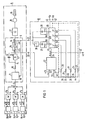
- the circuit part contained in the rectangle shown in dashed lines and designated by A shows an electricity meter operating according to the capacitor recharging method, as is known from the above-mentioned magazine "Technisches Messen atm", 1978, volume 11, pages 407 to 411. This is a three-phase meter.
- the current and voltage values U R , I R , U s , 1 8 , U T and I T that characterize the electrical energy consumption in the three-phase network are converted in converters 1 to 3 into proportional voltage signals ulR, u2R, u1S, u2S, u1T and u2T .
- the signals associated with each phase that is, for example, the voltage and current proportional signals u1 R and u2R associated with the network phase R, are processed in the multipliers 4 to 6 to form the power proportional signals P R , P s and P T.
- Time-division multipliers are preferably used as multipliers 4 to 6.
- the electric power taken from the characterizing still in the individual network phases R, S and T signals P R, P s and P T are pulsating voltages whose time average is proportional to the individual mains-system phases extracted electric powers.
- the signals P R , P s and P T are summed up to the sum signal S.
- the sum signal S is fed to the input of the quantizer 8.
- the quantizer 8 has a controllable polarity switch 9 for the sum signal, a downstream resistor 10 and an integrator 13 consisting of an amplifier 11 and an integration capacitor bridging the amplifier, and a downstream limit value element 14, the output 15 of the limit value element 14 being the output of the Quantizer 8 forms.
- the output 15 of the limit value element 14 is also connected to the control input 16 of the polarity switch 9.
- the sum signal S is integrated in the one position of the polarity switch 9 after conversion into a current i s in the integrator 13 until the output signal u13 of the integrator 13 reaches the upper limit value of the limit value element 14.
- a signal change occurs at the output 15 of the limit value element 14, by means of which the polarity of the sum signal S at the output of the polarity switch is changed at the control input 16 of the polarity switch 9.
- the current i s at the input of the integrator 13 now flows in the opposite direction, so that the output signal u13 now drops until the lower limit value G2 of the limit value element 14 is reached, whereupon a renewed signal change occurs at the output 15.
- the signal u13 at the output of the integrator 13 therefore has an essentially triangular shape and moves between the upper limit value G1 and the lower limit value G2.
- a pulse train u14 with power-proportional frequency thus arises at the output of quantizer 8.
- This pulse train u14 is reduced so far in the frequency divider 17 that a stepper motor 18 Roller counter 19 can be operated.
- the roller counter 19 displays the electrical energy drawn from the three network phases R, S and T by a consumer.
- the pulse multiplier circuit B has the input terminals 20 and 21, the output signal u13 of the integrator 13 being present on the former and the output signal u14 of the limit value element 14 being present on the latter.
- the pulse multiplier circuit B contains a voltage comparator 22, at one input 23 of which the signal u13 present at the input terminal 20 is guided.
- the output 24 of the voltage comparator 22 is connected to the count input 25 of an up-down counter 26.
- the up-down counter 26 has four binary outputs Q 0 , Q 1 , Q 2 and Q 3 with the valences 2 °, 2 1 , 2 2 and 2 3 .
- the up / down counter 26 can thus count a maximum of 16 pulses and output them in binary form at its binary outputs Q o to Q 3 .
- the binary outputs Q o to Q 3 are connected to the other input 27 of the voltage comparator 22 via an R / 2R network known per se.
- the binary output Q 3 is connected to the other input 27 of the voltage comparator 22 via the resistor 28.
- the binary output Q 2 is connected to the other input 27 via the series connection of the resistors 29 and 30.
- the binary output Q 1 is connected to the connection point 33 of the resistors 29 and 30 via the series connection of the resistors 31 and 32.
- the binary output Q o is connected to the connection point 36 of the resistors 31 and 32 via the series connection of the resistors 34 and 35.
- the resistors 28, 29, 31 and 34 have the same resistance value, which is twice as large as the resistance value of the resistors 30, 32 and 35, which also have resistance values of equal magnitude.
- the resistors 28, 29, 31 and 34 can have, for example, a resistance value of 200 kOhm, whereas the resistors 30, 32 and 35 have a resistance value of 100 kOhm.
- This R2 / R2 network produces an analog voltage signal u o at the other input 27, the value of which is gradually proportional to the content of the up-down counter 26. If the up-down counter 26 runs through the numerical values between 0 and 15 in chronological order, then the voltage u n assumes a step-like course.
- the up-down counter 26 can be controlled with respect to its counting direction via the input V / R in the sense that - if the signal u14 at this control input V / R has an H level - the up-down counter 26 has its on Counting input 25 counts pending pulses and that - if the signal u14 is low - a down or down counting takes place.
- the up-down counter 26 has a set input SZ. If a suitable pulse occurs at this set input SZ, then the maximum counter reading of 15 is set on the up / down counter 26, in which all the binary outputs Q o to Q 3 have an H level.
- the up-down counter 26 has a reset input R, by means of which the counter reading 0 and thus the L level at all binary outputs Q o to Q 3 are forced when a suitable pulse is received.
- the set input SZ is connected to the input terminal 21 via a differentiating element 37 and an inverting element 38.
- the reset input R of the up-down counter 26 is also connected to the input terminal 21 via a differentiator 39. Both the counting direction signal present at the control input V / R and the set or reset signal are thus derived from the signal u14.
- the output terminal of the pulse multiplier circuit B is provided with the reference numeral 40 and connected to the output 24 of the voltage comparator 22.
- This output signal up consists of individual pulses, 32 such pulses occurring between two signals of the signal u14. In this way, a thirty-two-fold increase in frequency is achieved compared to the output signal u14 of the quantizer 8.
- the up-down counter 26 can be designed as a C-MOS circuit.
- the positive and negative supply voltage + U v and - U v - as shown in broken lines in FIG. 1 - are supplied via terminals 41 and 42.
- the essentially triangular signal u13 fluctuates symmetrically with respect to the voltage zero point between a positive upper limit value G1 and a negative lower limit value G2 of equal magnitude
- the required shift of the voltage u n of the R / 2R network to negative voltages can be done in a simple manner take place that the input 27 of the voltage comparator 22 is connected via a resistor 43 to the terminal 42 carrying the negative supply voltage-U v and, moreover, the connection point 44 of the resistors 34 and 35 is also connected to the terminal 42 via a further resistor 45. This is shown in dashed lines in FIG. 1.
- the voltage comparator 22 can be implemented by an input-side operational amplifier and a downstream pulse shaper circuit, the pulse shaper circuit consisting of each signal change occurring in the voltage comparator 22 or the input-side operational amplifier in the voltage comparator 22 when the voltages u13 and u n are equal, in order to drive the counting input 25 of the up-down counter 26 derives a suitable pulse.
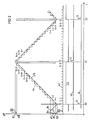
- the pulse diagram shown in Fig. 2 illustrates the operation of the pulse multiplier circuit B. That at the output 15 of the Limit value element 14, signal u14 in the form of a pulse train of square-wave signals, the frequency of which is proportional to the power drawn from the three network phases R. S, T, is shown in line 3 of FIG. 2.
- Line 1 of FIG. 2 shows the signal u13, which is essentially triangular in shape, at the output of the integrator 13.
- the signal u13 moves between the limit values G1 and G2 specified by the limit value element 14, the extremes of the signal u13 occurring at the times t0, t1 and t2 naturally coinciding with the signal change of the signal u14.
- a pulse i1 of the signal u R present at the reset input R of the up-down counter 26 is obtained from the rising edge of the signal u14 at the time t0 by the differentiator 39, as a result of which the up-down counter 26 is set to the value 0.
- the value 0 of the up-down counter 26 corresponds to the output-side voltage value u o of the signal u n supplied by the R / R2 network at the other input of the voltage comparator 22.
- the voltage value u o is above Au corresponding to the lower limit value G2 Minimum of the output signal u13 of the integrator 13. As soon as the rising signal u13 reaches the voltage value u o , the pulse 1 of the pulse train up shown in line 2 of FIG.
- a pulse i2 of the signal train U s present at the set input SZ of the up / down counter 26 is derived from the falling edge of the signal u14 shown in line 3, FIG. 2 via the inverting element 38 and the differentiating element 37.
- the up / down counter 26 is set to its maximum value of 15, which causes the signal U n to be raised again to the voltage value u15 at the input 27 of the voltage comparator 22. Since the voltage of the signal u13 now decreases, when the signal u13 reaches the voltage value u15, the pulse of the pulse train U p, designated 17, occurs.
- a pulse i3 of the signal u R present at the input R of the up-down counter 26 is now again generated at the time t2 via the differentiator 39, as a result of which the up-down counter 26 is reset to the value 0 becomes, whereupon the signal U n falls back to the voltage level u o .
- a new duty cycle of the pulse multiplier circuit 2 can thus begin.
- 32 pulses of the pulse train up occur at the output 40 due to the effect of the pulse multiplier circuit B in the period t2-t0 between two minima of the signal u13.
- a corresponding increase or decrease in the number of pulses falling in this time period at the output 40 of the pulse multiplier circuit can be achieved by using an up-down counter with a larger or smaller maximum memory content.
Landscapes
- Power Engineering (AREA)
- Physics & Mathematics (AREA)
- General Physics & Mathematics (AREA)
- Engineering & Computer Science (AREA)
- Measurement Of Resistance Or Impedance (AREA)
- Analogue/Digital Conversion (AREA)
- Metal Rolling (AREA)
- Electrical Discharge Machining, Electrochemical Machining, And Combined Machining (AREA)
- Control Of Eletrric Generators (AREA)
- Meter Arrangements (AREA)
- Disintegrating Or Milling (AREA)
- Inorganic Compounds Of Heavy Metals (AREA)
- Control Of El Displays (AREA)
- Finger-Pressure Massage (AREA)
- External Artificial Organs (AREA)
- Charge And Discharge Circuits For Batteries Or The Like (AREA)
- Electroluminescent Light Sources (AREA)
- Measuring Fluid Pressure (AREA)
- Saccharide Compounds (AREA)
- Transmitters (AREA)
- Dc Digital Transmission (AREA)
- Acyclic And Carbocyclic Compounds In Medicinal Compositions (AREA)
- Dc-Dc Converters (AREA)
Claims (5)
Priority Applications (1)
| Application Number | Priority Date | Filing Date | Title |
|---|---|---|---|
| AT82102915T ATE11965T1 (de) | 1981-04-16 | 1982-04-05 | Nach dem kondensatorumladeverfahren arbeitender elektronischer elektrizitaetszaehler. |
Applications Claiming Priority (2)
| Application Number | Priority Date | Filing Date | Title |
|---|---|---|---|
| DE3115522 | 1981-04-16 | ||
| DE19813115522 DE3115522A1 (de) | 1981-04-16 | 1981-04-16 | Nach dem kondensatorumladeverfahren arbeitender elektronischer elektrizitaetszaehler |
Publications (2)
| Publication Number | Publication Date |
|---|---|
| EP0063306A1 EP0063306A1 (fr) | 1982-10-27 |
| EP0063306B1 true EP0063306B1 (fr) | 1985-02-20 |
Family
ID=6130343
Family Applications (1)
| Application Number | Title | Priority Date | Filing Date |
|---|---|---|---|
| EP82102915A Expired EP0063306B1 (fr) | 1981-04-16 | 1982-04-05 | Compteur électronique employant l'échange de charge d'un condensateur |
Country Status (9)
| Country | Link |
|---|---|
| EP (1) | EP0063306B1 (fr) |
| JP (1) | JPS57182176A (fr) |
| AT (1) | ATE11965T1 (fr) |
| DE (2) | DE3115522A1 (fr) |
| DK (1) | DK168382A (fr) |
| ES (1) | ES8304316A1 (fr) |
| FI (1) | FI75060C (fr) |
| NO (1) | NO157716C (fr) |
| PT (1) | PT74761B (fr) |
Families Citing this family (3)
| Publication number | Priority date | Publication date | Assignee | Title |
|---|---|---|---|---|
| CH677037A5 (fr) * | 1987-08-06 | 1991-03-28 | Landis & Gyr Betriebs Ag | |
| EP0961124A3 (fr) * | 1998-05-28 | 2003-07-02 | Matsushita Electric Industrial Co., Ltd. | Instrument de type multi-circuit et transformateur de courant pour mesurer plusieurs variables d'énergie électrique |
| DE102004011023A1 (de) * | 2004-03-04 | 2005-09-15 | Siemens Ag | Drei- oder vierpoliger Niederspannungs-Leistungsschalter mit als Stromsensoren dienenden Rogowskispulen |
Family Cites Families (1)
| Publication number | Priority date | Publication date | Assignee | Title |
|---|---|---|---|---|
| DE2747385C2 (de) * | 1977-10-21 | 1983-12-29 | Siemens AG, 1000 Berlin und 8000 München | Elektronischer Wechselstromzähler |
-
1981
- 1981-04-16 DE DE19813115522 patent/DE3115522A1/de not_active Withdrawn
-
1982
- 1982-02-25 FI FI820644A patent/FI75060C/fi not_active IP Right Cessation
- 1982-04-05 DE DE8282102915T patent/DE3262379D1/de not_active Expired
- 1982-04-05 AT AT82102915T patent/ATE11965T1/de not_active IP Right Cessation
- 1982-04-05 EP EP82102915A patent/EP0063306B1/fr not_active Expired
- 1982-04-14 NO NO821218A patent/NO157716C/no unknown
- 1982-04-15 DK DK168382A patent/DK168382A/da active IP Right Grant
- 1982-04-15 ES ES511454A patent/ES8304316A1/es not_active Expired
- 1982-04-15 PT PT74761A patent/PT74761B/pt not_active IP Right Cessation
- 1982-04-16 JP JP57063785A patent/JPS57182176A/ja active Pending
Also Published As
| Publication number | Publication date |
|---|---|
| NO821218L (no) | 1982-10-18 |
| EP0063306A1 (fr) | 1982-10-27 |
| DK168382A (da) | 1982-10-17 |
| ES511454A0 (es) | 1983-02-16 |
| NO157716C (no) | 1988-05-04 |
| ES8304316A1 (es) | 1983-02-16 |
| JPS57182176A (en) | 1982-11-09 |
| NO157716B (no) | 1988-01-25 |
| FI75060C (fi) | 1988-04-11 |
| PT74761B (de) | 1983-10-28 |
| PT74761A (de) | 1982-05-01 |
| DE3115522A1 (de) | 1982-11-04 |
| FI75060B (fi) | 1987-12-31 |
| FI820644L (fi) | 1982-10-17 |
| DE3262379D1 (en) | 1985-03-28 |
| ATE11965T1 (de) | 1985-03-15 |
Similar Documents
| Publication | Publication Date | Title |
|---|---|---|
| DE3125664C2 (fr) | ||
| DE2845511A1 (de) | Batterieladeschaltung | |
| DE2162486B2 (de) | Digital gesteuerter Impulsgenerator | |
| DE1905176C3 (de) | Verfahren zur Analog-Digital-Umsetzung mit verbesserter Differentiallinearität der Umsetzung und Anordnung zur Durchführung dieses Verfahrens | |
| DE2333299B2 (de) | Schaltungsanordnung zur Umsetzung von Analog-Signalen in PCM-Signale und von PCM-Signalen in Analog-Signale | |
| DE68906896T2 (de) | Verfahren und vorrichtung zur kapazitaetsmessung und kapazitive verschiebungsmessung. | |
| DE2519668C3 (de) | Anordnung zur Erzeugung einer dem Produkt zweier analoger elektrischer Größen proportionalen Folge von Impulsen | |
| DE3329242A1 (de) | Schaltungsanordnung zum ueberpruefen des zeitlichen abstands von rechtecksignalen | |
| DE3519116A1 (de) | Gleichstrom/gleichstrom-wandler | |
| EP0063306B1 (fr) | Compteur électronique employant l'échange de charge d'un condensateur | |
| DE2239901A1 (de) | Konstantstromversorgung | |
| DE2449016A1 (de) | Schaltung zum messen des innenwiderstandes eines wechselstromnetzes | |
| EP0232763A1 (fr) | Compteur d'électricité électronique | |
| DE2105492B2 (de) | Elektronischer wechselstrom-zaehler | |
| DE2343092A1 (de) | Programmierbarer funktionsgenerator | |
| DE3001593A1 (de) | Spannungsfrequenzgeber fuer synchronmaschinen | |
| DE2454601A1 (de) | Verfahren und einrichtung zur mittelwerterfassung | |
| DE3014274C2 (fr) | ||
| DE2436238A1 (de) | Nicht linearer analog-digital-umsetzer zur verdichtungscodierung | |
| DE2246040A1 (de) | Steuersystem fuer die automatische zeitsteuerung eines vorgeschriebenen ablaufes von vorgaengen | |
| DE2610802A1 (de) | Elektronischer wirkverbrauchzaehler | |
| DE4101193C1 (fr) | ||
| DE2451271A1 (de) | Impulswertigkeitsumformer fuer einen elektronischen elektrizitaetszaehler | |
| DE2614383A1 (de) | Multiplizierer | |
| DE2330090C3 (de) | Bipolarer Spannungs-Frequenz-Umsetzer |
Legal Events
| Date | Code | Title | Description |
|---|---|---|---|
| PUAI | Public reference made under article 153(3) epc to a published international application that has entered the european phase |
Free format text: ORIGINAL CODE: 0009012 |
|
| AK | Designated contracting states |
Designated state(s): AT BE CH DE FR GB IT NL SE |
|
| 17P | Request for examination filed |
Effective date: 19830221 |
|
| ITF | It: translation for a ep patent filed | ||
| GRAA | (expected) grant |
Free format text: ORIGINAL CODE: 0009210 |
|
| AK | Designated contracting states |
Designated state(s): AT BE CH DE FR GB IT LI NL SE |
|
| REF | Corresponds to: |
Ref document number: 11965 Country of ref document: AT Date of ref document: 19850315 Kind code of ref document: T |
|
| REF | Corresponds to: |
Ref document number: 3262379 Country of ref document: DE Date of ref document: 19850328 |
|
| ET | Fr: translation filed | ||
| PLBE | No opposition filed within time limit |
Free format text: ORIGINAL CODE: 0009261 |
|
| STAA | Information on the status of an ep patent application or granted ep patent |
Free format text: STATUS: NO OPPOSITION FILED WITHIN TIME LIMIT |
|
| 26N | No opposition filed | ||
| PGFP | Annual fee paid to national office [announced via postgrant information from national office to epo] |
Ref country code: NL Payment date: 19870430 Year of fee payment: 6 |
|
| PG25 | Lapsed in a contracting state [announced via postgrant information from national office to epo] |
Ref country code: NL Effective date: 19881101 |
|
| NLV4 | Nl: lapsed or anulled due to non-payment of the annual fee | ||
| ITTA | It: last paid annual fee | ||
| PGFP | Annual fee paid to national office [announced via postgrant information from national office to epo] |
Ref country code: GB Payment date: 19920326 Year of fee payment: 11 |
|
| PGFP | Annual fee paid to national office [announced via postgrant information from national office to epo] |
Ref country code: AT Payment date: 19920327 Year of fee payment: 11 |
|
| PGFP | Annual fee paid to national office [announced via postgrant information from national office to epo] |
Ref country code: FR Payment date: 19920428 Year of fee payment: 11 Ref country code: BE Payment date: 19920428 Year of fee payment: 11 |
|
| PGFP | Annual fee paid to national office [announced via postgrant information from national office to epo] |
Ref country code: SE Payment date: 19920429 Year of fee payment: 11 |
|
| PG25 | Lapsed in a contracting state [announced via postgrant information from national office to epo] |
Ref country code: GB Effective date: 19930405 Ref country code: AT Effective date: 19930405 |
|
| PG25 | Lapsed in a contracting state [announced via postgrant information from national office to epo] |
Ref country code: SE Effective date: 19930406 |
|
| PG25 | Lapsed in a contracting state [announced via postgrant information from national office to epo] |
Ref country code: BE Effective date: 19930430 |
|
| PGFP | Annual fee paid to national office [announced via postgrant information from national office to epo] |
Ref country code: DE Payment date: 19930618 Year of fee payment: 12 |
|
| PGFP | Annual fee paid to national office [announced via postgrant information from national office to epo] |
Ref country code: CH Payment date: 19930712 Year of fee payment: 12 |
|
| BERE | Be: lapsed |
Owner name: SIEMENS A.G. BERLIN UND MUNCHEN Effective date: 19930430 |
|
| GBPC | Gb: european patent ceased through non-payment of renewal fee |
Effective date: 19930405 |
|
| PG25 | Lapsed in a contracting state [announced via postgrant information from national office to epo] |
Ref country code: FR Effective date: 19931229 |
|
| REG | Reference to a national code |
Ref country code: FR Ref legal event code: ST |
|
| PG25 | Lapsed in a contracting state [announced via postgrant information from national office to epo] |
Ref country code: LI Effective date: 19940430 Ref country code: CH Effective date: 19940430 |
|
| REG | Reference to a national code |
Ref country code: CH Ref legal event code: PL |
|
| PG25 | Lapsed in a contracting state [announced via postgrant information from national office to epo] |
Ref country code: DE Effective date: 19950103 |
|
| EUG | Se: european patent has lapsed |
Ref document number: 82102915.4 Effective date: 19931110 |