EP0063081B1 - Dispositif de montage de siège coulissant et règlable pour véhicule automobile - Google Patents
Dispositif de montage de siège coulissant et règlable pour véhicule automobile Download PDFInfo
- Publication number
- EP0063081B1 EP0063081B1 EP19820400620 EP82400620A EP0063081B1 EP 0063081 B1 EP0063081 B1 EP 0063081B1 EP 19820400620 EP19820400620 EP 19820400620 EP 82400620 A EP82400620 A EP 82400620A EP 0063081 B1 EP0063081 B1 EP 0063081B1
- Authority
- EP
- European Patent Office
- Prior art keywords
- roller
- seat
- rack
- support
- rollers
- Prior art date
- Legal status (The legal status is an assumption and is not a legal conclusion. Google has not performed a legal analysis and makes no representation as to the accuracy of the status listed.)
- Expired
Links
- 239000003831 antifriction material Substances 0.000 claims description 2
- 125000006850 spacer group Chemical group 0.000 description 22
- 238000005096 rolling process Methods 0.000 description 2
- 210000000080 chela (arthropods) Anatomy 0.000 description 1
- 230000000694 effects Effects 0.000 description 1
- 230000003100 immobilizing effect Effects 0.000 description 1
- 230000002093 peripheral effect Effects 0.000 description 1
- 230000000284 resting effect Effects 0.000 description 1
- 238000005728 strengthening Methods 0.000 description 1
Images

Classifications
-
- B—PERFORMING OPERATIONS; TRANSPORTING
- B60—VEHICLES IN GENERAL
- B60N—SEATS SPECIALLY ADAPTED FOR VEHICLES; VEHICLE PASSENGER ACCOMMODATION NOT OTHERWISE PROVIDED FOR
- B60N2/00—Seats specially adapted for vehicles; Arrangement or mounting of seats in vehicles
- B60N2/02—Seats specially adapted for vehicles; Arrangement or mounting of seats in vehicles the seat or part thereof being movable, e.g. adjustable
- B60N2/04—Seats specially adapted for vehicles; Arrangement or mounting of seats in vehicles the seat or part thereof being movable, e.g. adjustable the whole seat being movable
- B60N2/06—Seats specially adapted for vehicles; Arrangement or mounting of seats in vehicles the seat or part thereof being movable, e.g. adjustable the whole seat being movable slidable
Definitions
- the position of the seats of motor vehicles is, in general, adjustable longitudinally. To this end, the seats have so far been mounted directly or with the aid of intermediate parts on the vehicle floor via ball bearing slides. These slides are heavy, fragile and expensive.
- the patent FR-A-889 640 describes a vehicle seat comprising two lateral carriages mounted to slide relative to the body of the vehicle and each carrying two pairs of rollers between which the frame of the seat can move.
- each of these carriages is pivotally mounted a first pinion engaged with a fixed rack and a second pinion engaged with a rack integral with the frame, the first pinions and the second pinions being interconnected by transverse connecting shafts.
- This seat can practically not be detached from the body.
- the present invention relates to a device for mounting a vehicle seat comprising two parallel transverse elements, a longitudinal rack secured to the seat, a toothed means cooperating with the rack, and support rollers immobilized axially and capable of roll on support tracks of the seat, which avoids the use of slides and also allows, if desired, to separate the seat from the body.
- the device according to the invention is characterized in that the transverse elements consist of two spacers connected at each of their ends to the lateral members of the bodywork and on which the support rollers are mounted to rotate, and in that the device comprises , in addition, at least two bridges which are fixed to the seat in an at least partially removable manner and each of which embraces one of the spacers while maintaining the support tracks on the support rollers, the bridges or some of the tracks 'Support comprising a rib engaged in a groove of the corresponding roller or vice versa, this roller thus constituting a guide roller.
- the bridges hold the seat on the spacers and thus prevent it from inadvertently separating from the spacers, for example to tilt forwards in the event of a frontal impact.
- the spacers have the additional advantage of strengthening the structure of the body at the level of the seat line, so that the body resists particularly well the effects of the forces developed during a lateral impact and that the pilot and the passenger are protected in an area where safety is essential.
- one of the guide rollers comprises a toothed part constituting the pinion, the rack forming a support track, and the device includes means for immobilizing the rotating roller.
- the roller When the roller is immobilized, the rack cannot move and the seat is locked in position. However, it is possible to move the seat longitudinally when the roller is released.
- the device comprises a handle which is pivotally mounted on the front spacer and comprises a clean toothed part which comes into engagement with the rack under the action of elastic means.
- the seat is immobilized.
- the guide roller cooperating with the trigger guard can be a roller in contact with a support track, it thus constitutes both a guide roller and a support roller. But, in this case, the roller caught in pincers between the support track and the trigger guard, rolls on the trigger guard in the opposite direction to the direction of movement on this trigger guard, so that there is friction. To reduce the latter, it is possible to provide the rib of the roller or the trigger guard with a track in an anti-friction material, preferably flexible and slightly compressed.
- the guide roller cooperating with the trigger guard may also not cooperate with the support tracks, that is to say not be a support roller.
- the roller released from the tracks then rolls without friction on the trigger guard, pivoting in the opposite direction to the direction of rotation of the rollers cooperating with the support tracks.
- one of the spacers carries a guide and stop roller arranged substantially in the longitudinal median plane of the seat while the other spacer carries two guide rollers arranged in the vicinity of the edges side of the seat.
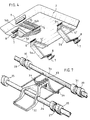
- each of the bridges is articulated by one of its ends at 6 on the base 2; its other end is fixed to this base by a locking hook 7 which is articulated at 8 on the trigger guard and can engage in a spout 9 fixed to the base.
- a roller 10 is rotatably mounted on the front spacer 3a, substantially in the longitudinal median plane of the seat.
- This roller has a central groove 11 in which is engaged a rectilinear median projection 12 provided under the base 2.
- the roller 10 is cut into pinions 13a and 13b which are engaged with racks 14a and 14b fixed under the base 2.
- a single trigger guard 5a which is located opposite the projection 12.
- This trigger guard carries a central projection 15 which is provided with a friction track 16 engaged in the groove 11.
- the rear spacer 3b carries, in the vicinity of each of the lateral edges of the seat 1, a roller 23 which can pivot freely on this spacer.
- This roller has a smooth periphery but comprises, like the roller 10, a central groove 11 'in which is engaged a straight web 12' provided under the base 2.
- This roller is immobilized laterally by two stops 24a and 24b fixed on the spacer 3b.
- Two bridges 5b are provided, each of which is located opposite one of the rollers 23.
- these bridges 12b have a central projection 15 which is provided with a friction track 16 engaged in the groove 11 'of the roller correspondent 23.
- the roller 10 In normal times, the roller 10 is immobilized and the seat cannot move longitudinally. However, if the plate 20 is removed from the roller 10, by means not shown in the drawing, the roller 10 is released and can pivot. The seat can move longitudinally by resting on the front roller 10 and on the rear rollers 23. During this movement, the seat is guided by the racks 13a and 13b and by the projections 12 and 12 'engaged in the grooves 11 and 11 ' shingles. If the plate 20 is released, the tabs 19 engage in the cavities 18 and again immobilize the roller 10 on the spacer 3a, the seat thus being locked in its new position. It can be seen that it is therefore possible to adjust the longitudinal position of the seat, within the limits authorized by the bridges 5a and 5b.
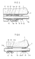
- the roller 10 is replaced by a set of two rollers 25 and 26, both mounted for rotation on the spacer.
- the roller 25 which guides the seat is not toothed and has a central groove 27 in which is engaged the projection 15 of the trigger guard 5a, this projection being here constituted by a stamping of the trigger guard.
- the roller 26 is toothed and engaged with the rack 14 which forms a support track.
- this roller carries on one of its flanks cavities 18 in which the tabs 19 of the plate 20 can engage.
- the two rollers 25 and 26 pivot in opposite directions, the roller 25 rolling without friction on the projection 15.
- a second toothed roller can be provided on the other side of the roller 25.
- the roller 23 is replaced by an assembly comprising a central roller 28 and two side rollers 29.
- the central roller 28 has a central groove 30 in which is engaged the projection 15 of the trigger guard 5b, that -ci being arranged in the longitudinal median plane of the base 2.
- Each of the side rollers 29 also has a central groove 31 in which is engaged one of the projections 12 'of the base 2.
- Each of these rollers is immobilized laterally by two stops 24a and 24b, fixed on the spacer. Again, when the seat is moved, the rollers 28 and 29 can pivot in the opposite direction, therefore rolling without friction on the projections on which they are engaged.
- the toothed roller 10 is further replaced by a smooth roller 25.
- a handle 32 which is pivotally mounted on the spacer 3a and has a toothing 33 which can engage, under the action of springs 34, in a rack provided under the base 2.
- this rack does not form a support track for the seat, the seat has a rib 12 engaged in the groove 27 of the roller 25.
- the guide rollers could comprise not grooves, but peripheral ribs engaged in grooves of the support tracks and bridges.
Landscapes
- Engineering & Computer Science (AREA)
- Aviation & Aerospace Engineering (AREA)
- Transportation (AREA)
- Mechanical Engineering (AREA)
- Seats For Vehicles (AREA)
Applications Claiming Priority (2)
| Application Number | Priority Date | Filing Date | Title |
|---|---|---|---|
| FR8107314 | 1981-04-07 | ||
| FR8107314A FR2503062A1 (fr) | 1981-04-07 | 1981-04-07 | Montage de siege de vehicule |
Publications (2)
| Publication Number | Publication Date |
|---|---|
| EP0063081A1 EP0063081A1 (fr) | 1982-10-20 |
| EP0063081B1 true EP0063081B1 (fr) | 1985-07-17 |
Family
ID=9257294
Family Applications (1)
| Application Number | Title | Priority Date | Filing Date |
|---|---|---|---|
| EP19820400620 Expired EP0063081B1 (fr) | 1981-04-07 | 1982-04-05 | Dispositif de montage de siège coulissant et règlable pour véhicule automobile |
Country Status (3)
| Country | Link |
|---|---|
| EP (1) | EP0063081B1 (enExample) |
| DE (1) | DE3264746D1 (enExample) |
| FR (1) | FR2503062A1 (enExample) |
Family Cites Families (5)
| Publication number | Priority date | Publication date | Assignee | Title |
|---|---|---|---|---|
| BE454798A (enExample) * | 1942-09-07 | |||
| DE1037878B (de) * | 1954-12-15 | 1958-08-28 | Keiper Fa F | Sitz fuer Fahrzeuge, insbesondere Personenkraftwagen |
| JPS5430163B2 (enExample) * | 1973-09-14 | 1979-09-28 | ||
| FR2419839A1 (fr) * | 1978-03-15 | 1979-10-12 | Tubauto | Dispositif de maintien d'un siege sur le plancher d'un vehicule |
| FR2468478A1 (fr) * | 1979-11-05 | 1981-05-08 | Faure Bertrand | Perfectionnements aux sieges de vehicules et aux chassis de vehicules equipes de tels sieges |
-
1981
- 1981-04-07 FR FR8107314A patent/FR2503062A1/fr active Granted
-
1982
- 1982-04-05 EP EP19820400620 patent/EP0063081B1/fr not_active Expired
- 1982-04-05 DE DE8282400620T patent/DE3264746D1/de not_active Expired
Also Published As
| Publication number | Publication date |
|---|---|
| DE3264746D1 (en) | 1985-08-22 |
| EP0063081A1 (fr) | 1982-10-20 |
| FR2503062B1 (enExample) | 1983-05-20 |
| FR2503062A1 (fr) | 1982-10-08 |
Similar Documents
| Publication | Publication Date | Title |
|---|---|---|
| EP0888926B1 (fr) | Siège de véhicule doté d'un dispositif de protection du cou en cas de choc arrière | |
| EP0947380B1 (fr) | Dispositif de crémaillère rapportée en fond de glissière | |
| EP0635397B1 (fr) | Porte-bagages pour véhicule automobile | |
| FR2864481A1 (fr) | Agencement pour le montage d'un siege sur le plancher d'un vehicule au moyen de plots de guidage escamotables | |
| EP0265317A1 (fr) | Dispositif linéaire de réglage rapide et de blocage d'une pièce mobile par rapport à une pièce fixe, applicable notamment au réglage de guide de table de machines à bois | |
| FR2645810A1 (fr) | Dispositif d'amenagement des sieges dans un vehicule, notamment utilitaire | |
| EP0949111B1 (fr) | Système d'arrimage modulable à commande par cames | |
| EP0800952B1 (fr) | Siège de véhicule, déplaçable vers l'avant pour accéder à un espace arrière | |
| FR2524285A1 (fr) | Siege transformable, notamment de vehicule automobile | |
| EP1000831B1 (fr) | Siège tournant à mouvement perfectionné, notamment pour véhicule ferroviaire | |
| EP1190893A2 (fr) | Appui-tête à plusieurs positions et siège muni de l'appui-tète | |
| FR2977202A1 (fr) | Siege pour un vehicule | |
| EP0063081B1 (fr) | Dispositif de montage de siège coulissant et règlable pour véhicule automobile | |
| FR3041577A1 (fr) | Mecanisme de verrouillage, ensemble interieur de vehicule et vehicule correspondant | |
| FR2689825A1 (fr) | Appui-tête pour siège de véhicule automobile. | |
| EP2449920B1 (fr) | Dispositif de verrouillage de panneaux d'une table pliable, flanc support de table et table de tennis de table équipés d'un tel dispositif | |
| EP0192006B1 (fr) | Siège de véhicule automobile | |
| EP1347136B1 (fr) | Ensemble de support et de guidage pour porte coulissante et porte correspondante | |
| EP1808330B1 (fr) | Siège pour véhicule automobile mobile selon un premier axe x et un second axe y et véhicule automobile comprenant un tel siège | |
| EP1619070B1 (fr) | Dispositif de guidage pour un ensemble mobile | |
| EP3162614B1 (fr) | Siège pour véhicule ayant un mécanisme de limitation de coulissement | |
| EP1726487B1 (fr) | Ensemble coulissant pour habitacle de véhicule | |
| FR3062609A1 (fr) | Dispositif de verrouillage reversible a palonnier de la position longitudinale d'un siege et ensemble de siege le comprenant | |
| FR2879980A1 (fr) | Dispositif de console amovible coulissante pour vehicule automobile et vehicule automobile equipe d'un tel dispositif | |
| FR3160656A1 (fr) | Dispositif d’accrochage de boucle de ceinture de sécurité |
Legal Events
| Date | Code | Title | Description |
|---|---|---|---|
| PUAI | Public reference made under article 153(3) epc to a published international application that has entered the european phase |
Free format text: ORIGINAL CODE: 0009012 |
|
| AK | Designated contracting states |
Designated state(s): DE GB IT |
|
| 17P | Request for examination filed |
Effective date: 19821025 |
|
| ITF | It: translation for a ep patent filed | ||
| GRAA | (expected) grant |
Free format text: ORIGINAL CODE: 0009210 |
|
| AK | Designated contracting states |
Designated state(s): DE GB IT |
|
| REF | Corresponds to: |
Ref document number: 3264746 Country of ref document: DE Date of ref document: 19850822 |
|
| ITPR | It: changes in ownership of a european patent |
Owner name: OFFERTA DI LICENZA AL PUBBLICO |
|
| PLBE | No opposition filed within time limit |
Free format text: ORIGINAL CODE: 0009261 |
|
| STAA | Information on the status of an ep patent application or granted ep patent |
Free format text: STATUS: NO OPPOSITION FILED WITHIN TIME LIMIT |
|
| 26N | No opposition filed | ||
| PGFP | Annual fee paid to national office [announced via postgrant information from national office to epo] |
Ref country code: GB Payment date: 19900331 Year of fee payment: 9 |
|
| PGFP | Annual fee paid to national office [announced via postgrant information from national office to epo] |
Ref country code: DE Payment date: 19900522 Year of fee payment: 9 |
|
| PG25 | Lapsed in a contracting state [announced via postgrant information from national office to epo] |
Ref country code: GB Effective date: 19910405 |
|
| GBPC | Gb: european patent ceased through non-payment of renewal fee | ||
| PG25 | Lapsed in a contracting state [announced via postgrant information from national office to epo] |
Ref country code: DE Effective date: 19920201 |