EP0062621A2 - Cutting insert for thread cutting - Google Patents
Cutting insert for thread cutting Download PDFInfo
- Publication number
- EP0062621A2 EP0062621A2 EP82850054A EP82850054A EP0062621A2 EP 0062621 A2 EP0062621 A2 EP 0062621A2 EP 82850054 A EP82850054 A EP 82850054A EP 82850054 A EP82850054 A EP 82850054A EP 0062621 A2 EP0062621 A2 EP 0062621A2
- Authority
- EP
- European Patent Office
- Prior art keywords
- insert
- cutting
- teeth
- cutting insert
- block
- Prior art date
- Legal status (The legal status is an assumption and is not a legal conclusion. Google has not performed a legal analysis and makes no representation as to the accuracy of the status listed.)
- Withdrawn
Links
Images
Classifications
-
- B—PERFORMING OPERATIONS; TRANSPORTING
- B23—MACHINE TOOLS; METAL-WORKING NOT OTHERWISE PROVIDED FOR
- B23B—TURNING; BORING
- B23B27/00—Tools for turning or boring machines; Tools of a similar kind in general; Accessories therefor
- B23B27/14—Cutting tools of which the bits or tips or cutting inserts are of special material
- B23B27/16—Cutting tools of which the bits or tips or cutting inserts are of special material with exchangeable cutting bits or cutting inserts, e.g. able to be clamped
- B23B27/1614—Cutting tools of which the bits or tips or cutting inserts are of special material with exchangeable cutting bits or cutting inserts, e.g. able to be clamped with plate-like cutting inserts of special shape clamped against the walls of the recess in the shank by a clamping member acting upon the wall of a hole in the insert
-
- B—PERFORMING OPERATIONS; TRANSPORTING
- B23—MACHINE TOOLS; METAL-WORKING NOT OTHERWISE PROVIDED FOR
- B23B—TURNING; BORING
- B23B27/00—Tools for turning or boring machines; Tools of a similar kind in general; Accessories therefor
- B23B27/06—Profile cutting tools, i.e. forming-tools
- B23B27/065—Thread-turning tools
-
- B—PERFORMING OPERATIONS; TRANSPORTING
- B23—MACHINE TOOLS; METAL-WORKING NOT OTHERWISE PROVIDED FOR
- B23B—TURNING; BORING
- B23B2200/00—Details of cutting inserts
- B23B2200/36—Other features of cutting inserts not covered by B23B2200/04 - B23B2200/32
- B23B2200/3618—Fixation holes
-
- B—PERFORMING OPERATIONS; TRANSPORTING
- B23—MACHINE TOOLS; METAL-WORKING NOT OTHERWISE PROVIDED FOR
- B23B—TURNING; BORING
- B23B2250/00—Compensating adverse effects during turning, boring or drilling
- B23B2250/12—Cooling and lubrication
-
- B—PERFORMING OPERATIONS; TRANSPORTING
- B23—MACHINE TOOLS; METAL-WORKING NOT OTHERWISE PROVIDED FOR
- B23B—TURNING; BORING
- B23B2260/00—Details of constructional elements
- B23B2260/138—Screw threads
- B23B2260/1386—Screw threads with trapezoidal thread profile
-
- B—PERFORMING OPERATIONS; TRANSPORTING
- B23—MACHINE TOOLS; METAL-WORKING NOT OTHERWISE PROVIDED FOR
- B23B—TURNING; BORING
- B23B2270/00—Details of turning, boring or drilling machines, processes or tools not otherwise provided for
- B23B2270/16—Constructions comprising three or more similar components
Landscapes
- Engineering & Computer Science (AREA)
- Mechanical Engineering (AREA)
- Cutting Tools, Boring Holders, And Turrets (AREA)
- Table Equipment (AREA)
Abstract
The invention provides a cutting insert for thread cutting operations of reversible type. The insert is prismatic in shape, one side surface of which being serrated so as to expose an even number of cutting teeth, the opposite side surface of which insert being intended as a side supporting surface. The insert is properly designed for grinding purposes and simultaneously enables stable clamping into a complementary shape of an insert receiving place of a toolholder, primarily because of two non-centrally passing clamp pin receiving bores.
Description
- The present invention relates to a cutting insert of indexable type, and more specifically a cutting insert for high-speed thread cutting.
- Various attempts have been made in cutting threads with inserts of cemented carbide material to pattern the cuts of the insert teeth with a view to assuring a resultant chip which reduces the difficulties of packing and binding in the cutting throat. Examples of the type of cuts, which have been employed, are disclosed for instance in US Patent No. 3.176.330. Usually a plurality of such thread cutting inserts are clamped into place in a carrier and mounted in a rotary spindle head and are rotated concurrently at relatively high speeds about the axis of a workpiece during the threading operation.
- A common disadvantage with all these prior art inserts for high speed thread cutting is that they are not indexable or reversible in nature, they are not secured into their insert sites in a fully stable manner and usually they are clamped into place in a carrier block by clamping means comprising a movable clamp member and additionally a chip breaker interposed between the clamp member and the leading face of the insert.
- It is an object of the present invention to provide a new type of insert for thread cutting purposes and simultanef ously make such insert adapted for a simplified and more stable clamping into its insert-receiving pocket of a pertaining tool holder.
- The insert of the present invention comprises a block of basically prismatic shape having parallel top and bottom surfaces and four side surfaces therebetween, one of which side surfaces defines a side support surface and two of which define transversely extending block end surfaces, said insert being characterized in that the side surface located opposite said side support surface is serrated so as to expose an even number of cutting teeth extending entirely between the top and bottom surfaces, the distance between the front end face of said cutting teeth and said side support surface measured transversely of the block being successively increasing in an order of succession from the first tooth to and including half the number of teeth whereas corresponding distance between the subsequent half number of teeth and said side support surface decreasing similarly.
- Other essential features of the invention will be more readily apparent from the following detailed description in combination with the corresponding drawings in which
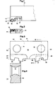
- Fig. 1 shows a longitudinal section of a tool provided with a thread cutting insert of the invention,
- Fig. 2 shows a section, in 900 angularly disposed position from Fig. 1, of the insert and insert-receiving cartridge,
- Fig. 3 shows an enlarged top view of the thread cutting insert of the invention; and
- Fig. 4 shows a section along the line IV-IV in Fig. 3.
- Referring to the drawings, Fig. 1 illustrates a tool consisting of a
bar 10 provided with a holder or acartridge 11. In thecartridge 11 there is located acutting insert 12, and ashim plate 13 supported against complementary support surfaces of a recess, said insert and saidshim plate 13 being adapted to be jointly clamped into thecartridge 11 by means of clamping means (not shown) to be engaged intobores cartridge 11 is similarly clamped into the bar with clamping means (not shown) engaging two radially disposed apertures, 16, 17 passing through said cartridge. - The illustrated
insert 12 of the invention is in the shape of a rectangular block and therefore comprises atop surface 18 and abottom surface 19 parallel with each other. Additionally there are two surfaces extending transversely of the block defining parallelblock end surfaces end surfaces cartridge 11, the other opposite side surface being serrated so as to define an even number of cuttingteeth bottom surfaces front end face side support surface 22, measured transversely of the block, being successively increasing in an order to succession from thefirst tooth 23 to and includingtooth 24, whereas the distance between front faces 31, 32 of saidside surface 22 andsubsequent teeth teeth Chip breaking grooves bottom surfaces groove 27 is located ontop surface 18 on the top side of cuttingteeth other chip groove 28 is provided in thebottom surface 19adjacent cutting teeth - When subjected to a thread cutting operation only the two
cutting teeth teeth teeth insert 12 is as already indicated clamped into saidcartridge 11 by means of pin lock means (not shown) that engages with the twobores bottom surfaces bores - The advantages of the insert for thread cutting inserts described above is primarily that it is reversible and as such very well suited for grinding and regrinding operations. It enables a very stable clamping because of its two non-centrally passing bores, which both can be engaged with correspondingly dimensioned pin locking means. Because of its reversible shape and nature one set of cutting teeth is always protected from wear mechanisms when the remainder of the cutting teeth are engaged in a cutting operation.
Claims (5)
1. Cutting insert for thread cutting operations comprising a block of basically prismatic shape confined by parallel top and bottom surfaces and four side surfaces therebetween, two of which side surface being transversely extending block end surfaces adapted to function as end supporting surfaces, characterized in that one of said side surfaces is adapted to function as a side supporting surface (22), whereas the opposite side surface being serrated so as to expose an even number of cutting teeth (23, 24, 25, 26) that extend entirely between the top surface (18) and the bottom surface (19), the distance between the front end faces (29, 30, 31, 32) of said cutting teeth and said side support surface (22) measured transversely of the block being successively increasing in an order of succession from the first tooth to and including half the number of teeth whereas corresponding distance between the subsequent half number of teeth and said side support surface decreasing similarly.
2. Cutting insert as defined in claim 1, characterized in that the insert is in the shape of a rectangular block and the cutting teeth (23, 24, 25, 26) being trapezoidal in shape.
3. Cutting insert as defined in claim 1, characterized in that two chip grooves (27, 28) being provided in such manner that one groove (27) is formed as a depression into the top surface (18) to provide the rake face for half the number of teeth, the second groove (28) being formed into the bottom surface (19) to provide rake face of the remaining teeth.
4. Cutting insert as defined in claim 1, characterized in that the insert is provided with two holes (14, 15), which pass non-centrally through the top and bottom surfaces (18, 19) disposed to receive a pin member to secure the insert into clamping engagement with complementary support surfaces of a recess in a holder (10).
5. Cutting insert as defined in claim 3, characterized in that each of said chip grooves (27, 28) consists of a depression initially increasing in depth in a direction away from the front end face of the teeth and thereafter decreasing in said direction.
Applications Claiming Priority (2)
| Application Number | Priority Date | Filing Date | Title |
|---|---|---|---|
| DE3114104 | 1981-04-08 | ||
| DE19813114104 DE3114104A1 (en) | 1981-04-08 | 1981-04-08 | THREADING INSERT FOR THREADING |
Publications (2)
| Publication Number | Publication Date |
|---|---|
| EP0062621A2 true EP0062621A2 (en) | 1982-10-13 |
| EP0062621A3 EP0062621A3 (en) | 1983-08-31 |
Family
ID=6129628
Family Applications (1)
| Application Number | Title | Priority Date | Filing Date |
|---|---|---|---|
| EP82850054A Withdrawn EP0062621A3 (en) | 1981-04-08 | 1982-03-16 | Cutting insert for thread cutting |
Country Status (3)
| Country | Link |
|---|---|
| EP (1) | EP0062621A3 (en) |
| JP (1) | JPS5815627A (en) |
| DE (1) | DE3114104A1 (en) |
Cited By (8)
| Publication number | Priority date | Publication date | Assignee | Title |
|---|---|---|---|---|
| EP0113332A1 (en) * | 1983-01-03 | 1984-07-11 | Metallwerk Plansee Gesellschaft M.B.H. | Cutting insert for thread-cutting |
| EP0145167A1 (en) * | 1983-10-14 | 1985-06-19 | Stellram Limited | Improvements in or relating to thread cutting |
| US4913604A (en) * | 1987-09-23 | 1990-04-03 | Vargus Ltd. Tool Manufacturing Co. | Thread milling tool |
| ES2088721A2 (en) * | 1993-05-13 | 1996-08-16 | Losse Pedro Farrarons | Methods for obtaining cutting tools, and cutting tools obtained by these methods. |
| US5873684A (en) * | 1997-03-29 | 1999-02-23 | Tool Flo Manufacturing, Inc. | Thread mill having multiple thread cutters |
| US8113746B2 (en) * | 2009-03-27 | 2012-02-14 | Kyocera Corporation | Cutting insert, cutting tool, and method of cutting workpiece using the same |
| CN103624343A (en) * | 2013-11-28 | 2014-03-12 | 昆山华辰精密工具有限公司 | Tool for machining casing pipe with buttress threads |
| US9931698B2 (en) | 2013-05-20 | 2018-04-03 | Tungaloy Corporation | Cutting insert for threading, tool body and cutting tool |
Families Citing this family (2)
| Publication number | Priority date | Publication date | Assignee | Title |
|---|---|---|---|---|
| DE3632296A1 (en) * | 1986-09-23 | 1988-04-07 | Vargus Ltd Tool Manufacturing | THREAD MILLING TOOL |
| JP6318558B2 (en) * | 2013-11-11 | 2018-05-09 | 三菱マテリアル株式会社 | Cutting insert and replaceable edge drilling tool |
Citations (10)
| Publication number | Priority date | Publication date | Assignee | Title |
|---|---|---|---|---|
| BE350520A (en) * | ||||
| BE389598A (en) * | ||||
| DE440367C (en) * | 1927-02-01 | Emil Baumann | Round thread chaser with two cutting edges for internal threads, especially for pipe sleeves | |
| GB477568A (en) * | 1936-10-16 | 1938-01-03 | P R Jackson & Co Ltd | Improvements in and relating to rack cutters for cutting internal gears |
| CH262604A (en) * | 1944-10-18 | 1949-07-15 | Lambrecht Julien Victor | Method for forming a screw thread and tool for carrying out this method. |
| DE846650C (en) * | 1951-04-06 | 1952-09-15 | Zahnraederfabrik Augsburg Vorm | Hobbing cutter for helical spur gears |
| DE1124786B (en) * | 1958-12-16 | 1962-03-01 | Fritz Kleinstueck | Double-conical, helical hobbing cutter or grinding body for the production of straight and helical-toothed, involute-shaped internal gear rims |
| US3176330A (en) * | 1962-12-06 | 1965-04-06 | Pipe Machinery Company | Coolant discharge device for cutting tool |
| DE2637757A1 (en) * | 1976-08-21 | 1978-02-23 | Hertel Karl | Form tool for cutting screw thread - has two sets of teeth arranged symmetrically for easy interchange |
| GB2030899A (en) * | 1978-10-04 | 1980-04-16 | Igman Sa | A detachable blade for a cutting tool |
-
1981
- 1981-04-08 DE DE19813114104 patent/DE3114104A1/en not_active Withdrawn
-
1982
- 1982-03-16 EP EP82850054A patent/EP0062621A3/en not_active Withdrawn
- 1982-04-08 JP JP5743082A patent/JPS5815627A/en active Pending
Patent Citations (10)
| Publication number | Priority date | Publication date | Assignee | Title |
|---|---|---|---|---|
| BE350520A (en) * | ||||
| BE389598A (en) * | ||||
| DE440367C (en) * | 1927-02-01 | Emil Baumann | Round thread chaser with two cutting edges for internal threads, especially for pipe sleeves | |
| GB477568A (en) * | 1936-10-16 | 1938-01-03 | P R Jackson & Co Ltd | Improvements in and relating to rack cutters for cutting internal gears |
| CH262604A (en) * | 1944-10-18 | 1949-07-15 | Lambrecht Julien Victor | Method for forming a screw thread and tool for carrying out this method. |
| DE846650C (en) * | 1951-04-06 | 1952-09-15 | Zahnraederfabrik Augsburg Vorm | Hobbing cutter for helical spur gears |
| DE1124786B (en) * | 1958-12-16 | 1962-03-01 | Fritz Kleinstueck | Double-conical, helical hobbing cutter or grinding body for the production of straight and helical-toothed, involute-shaped internal gear rims |
| US3176330A (en) * | 1962-12-06 | 1965-04-06 | Pipe Machinery Company | Coolant discharge device for cutting tool |
| DE2637757A1 (en) * | 1976-08-21 | 1978-02-23 | Hertel Karl | Form tool for cutting screw thread - has two sets of teeth arranged symmetrically for easy interchange |
| GB2030899A (en) * | 1978-10-04 | 1980-04-16 | Igman Sa | A detachable blade for a cutting tool |
Cited By (10)
| Publication number | Priority date | Publication date | Assignee | Title |
|---|---|---|---|---|
| EP0113332A1 (en) * | 1983-01-03 | 1984-07-11 | Metallwerk Plansee Gesellschaft M.B.H. | Cutting insert for thread-cutting |
| WO1984002671A1 (en) * | 1983-01-03 | 1984-07-19 | Plansee Metallwerk | Cutting device for threading |
| EP0145167A1 (en) * | 1983-10-14 | 1985-06-19 | Stellram Limited | Improvements in or relating to thread cutting |
| US5098232A (en) * | 1983-10-14 | 1992-03-24 | Stellram Limited | Thread cutting tool |
| US4913604A (en) * | 1987-09-23 | 1990-04-03 | Vargus Ltd. Tool Manufacturing Co. | Thread milling tool |
| ES2088721A2 (en) * | 1993-05-13 | 1996-08-16 | Losse Pedro Farrarons | Methods for obtaining cutting tools, and cutting tools obtained by these methods. |
| US5873684A (en) * | 1997-03-29 | 1999-02-23 | Tool Flo Manufacturing, Inc. | Thread mill having multiple thread cutters |
| US8113746B2 (en) * | 2009-03-27 | 2012-02-14 | Kyocera Corporation | Cutting insert, cutting tool, and method of cutting workpiece using the same |
| US9931698B2 (en) | 2013-05-20 | 2018-04-03 | Tungaloy Corporation | Cutting insert for threading, tool body and cutting tool |
| CN103624343A (en) * | 2013-11-28 | 2014-03-12 | 昆山华辰精密工具有限公司 | Tool for machining casing pipe with buttress threads |
Also Published As
| Publication number | Publication date |
|---|---|
| JPS5815627A (en) | 1983-01-29 |
| EP0062621A3 (en) | 1983-08-31 |
| DE3114104A1 (en) | 1982-10-28 |
Similar Documents
| Publication | Publication Date | Title |
|---|---|---|
| US4189264A (en) | Cutting insert and chip control assembly | |
| EP0042237B1 (en) | Cutting tool and cutter insert therefor | |
| US3187406A (en) | Cutting insert | |
| EP0596844B1 (en) | Cutting insert for grooving operations | |
| US4248553A (en) | Cutting insert configuration | |
| EP0571932B1 (en) | Exchangeable milling cutting inserts | |
| EP0213494B1 (en) | Cutting tool insert having cutting edges with recesses | |
| US4575286A (en) | Gear cutter assembly | |
| US4443136A (en) | Machine cutting tool | |
| US5333972A (en) | Special boring insert | |
| KR101036116B1 (en) | A cutting insert, a cutting tool, a shim and a method | |
| US4531864A (en) | Cutting insert | |
| US4527930A (en) | Ball nose end cutting tool | |
| EP1629914B1 (en) | Indexable cutting insert | |
| US5256008A (en) | Cutting tool for a peeling operation | |
| US3844008A (en) | Cutting tool | |
| US3733664A (en) | Cutting insert | |
| US3416209A (en) | Cutting tool | |
| US3821837A (en) | Cutting insert and cutting tool | |
| US20070217876A1 (en) | Knife plate and tool for machining bore surfaces | |
| EP0084223A2 (en) | Consumable self-regenerative ledge cutting insert | |
| EP1415742B1 (en) | Indexible turning tool for chipforming machining | |
| EP0062621A2 (en) | Cutting insert for thread cutting | |
| US3579777A (en) | Helical end mill | |
| US5779400A (en) | Small-shank tool for automatic lathes |
Legal Events
| Date | Code | Title | Description |
|---|---|---|---|
| PUAI | Public reference made under article 153(3) epc to a published international application that has entered the european phase |
Free format text: ORIGINAL CODE: 0009012 |
|
| AK | Designated contracting states |
Designated state(s): BE DE FR GB IT SE |
|
| 17P | Request for examination filed |
Effective date: 19830328 |
|
| PUAL | Search report despatched |
Free format text: ORIGINAL CODE: 0009013 |
|
| AK | Designated contracting states |
Designated state(s): BE DE FR GB IT SE |
|
| STAA | Information on the status of an ep patent application or granted ep patent |
Free format text: STATUS: THE APPLICATION IS DEEMED TO BE WITHDRAWN |
|
| 18D | Application deemed to be withdrawn |
Effective date: 19840828 |
|
| RIN1 | Information on inventor provided before grant (corrected) |
Inventor name: LAGERBERG, STIG ERIK VALTER Inventor name: AHLFORS, LEIF HARRY |