EP0062529A2 - Verzögerungskompensation in elektromagnetischen Ablenkungssystemen - Google Patents
Verzögerungskompensation in elektromagnetischen Ablenkungssystemen Download PDFInfo
- Publication number
- EP0062529A2 EP0062529A2 EP82301796A EP82301796A EP0062529A2 EP 0062529 A2 EP0062529 A2 EP 0062529A2 EP 82301796 A EP82301796 A EP 82301796A EP 82301796 A EP82301796 A EP 82301796A EP 0062529 A2 EP0062529 A2 EP 0062529A2
- Authority
- EP
- European Patent Office
- Prior art keywords
- signal
- input signal
- deflection circuit
- correction
- beam position
- Prior art date
- Legal status (The legal status is an assumption and is not a legal conclusion. Google has not performed a legal analysis and makes no representation as to the accuracy of the status listed.)
- Withdrawn
Links
Images
Classifications
-
- H—ELECTRICITY
- H04—ELECTRIC COMMUNICATION TECHNIQUE
- H04N—PICTORIAL COMMUNICATION, e.g. TELEVISION
- H04N9/00—Details of colour television systems
- H04N9/12—Picture reproducers
- H04N9/16—Picture reproducers using cathode ray tubes
- H04N9/28—Arrangements for convergence or focusing
-
- H—ELECTRICITY
- H04—ELECTRIC COMMUNICATION TECHNIQUE
- H04N—PICTORIAL COMMUNICATION, e.g. TELEVISION
- H04N3/00—Scanning details of television systems; Combination thereof with generation of supply voltages
- H04N3/10—Scanning details of television systems; Combination thereof with generation of supply voltages by means not exclusively optical-mechanical
- H04N3/16—Scanning details of television systems; Combination thereof with generation of supply voltages by means not exclusively optical-mechanical by deflecting electron beam in cathode-ray tube, e.g. scanning corrections
- H04N3/22—Circuits for controlling dimensions, shape or centering of picture on screen
- H04N3/23—Distortion correction, e.g. for pincushion distortion correction, S-correction
- H04N3/233—Distortion correction, e.g. for pincushion distortion correction, S-correction using active elements
- H04N3/2335—Distortion correction, e.g. for pincushion distortion correction, S-correction using active elements with calculating means
Definitions
- the present invention relates generally to CRT electron beam deflection systems, and more particularly to the compensation of delays inherent in electromagnetic deflection systems.
- Video type display devices operating over a wide range of horizontal scan rates thus require some means of compensating for the effects of deflection system delays on beam position-related correction signals, such as those for beam convergence or top and bottom raster tilt.
- the present invention solves the above-identified problem by advancing the correction signals an amount sufficient to cancel out the deflection system delay(s).
- the required advance may be provided, for example, through the use of a phase lock loop, but a preferable approach is to add a d.c. level shift to a beam position-related signal from which the correction signal is derived.
- a correction waveform generator for an electromagnetically-deflected video display is compensated for deflection system delays by adding an appropriate d.c. level shift to a ramp signal from which the correction waveforms are derived.
- This d.c. offset causes the correction signals to be time advanced an amount sufficient to compensate for delays in the deflection system and its drive circuitry.
- This delay compensation method i.e., adding a d.c. level shift to a beam position-related ramp signal from which the correction signal is derived -- may be used for both the beam convergence and the vertical raster top and bottom tilt correction signals.
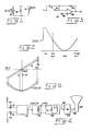
- FIG. 1 illustrates a simplified model of an electromagnetic deflection circuit that includes a CRT deflection coil L, a loss element R representing the effective parallel resistance associated with the coil, and a suitable current source S. It can be shown that for an input current I (t), where the current I L (t) in inductor L is The gain coefficients K' 2 , K' 3 , K' 4 , etc. are small with respect to the coefficients of the corresponding powers of t in I c (t-L/R) when L/R « t A /2, t A being the active time of the CRT's horizontal sweep.
- FIG. 2 illustrates graphically the current I (t) generated by source S.
- the desired correction waveform here a parabola
- the transient resulting from the expoential term K e e -R/Lt will be substantially decayed.
- the field-producing current through the coil thus may be approximated by I L (t) ⁇ I C (t-L/R). Accordingly, the delay produced by loss element R can be compensated by a time advance term +L/R.
- the coil driver circuit shown (in simplified form) in FIG. 3 can be adjusted to cancel the delay produced by the deflection coil's loss element R.
- the circuit includes an operational amplifier OA whose noninverting input is referenced to ground by a resistor R O .
- An input resistor R 1 connected to the amplifier's inverting (-) input is bridged by a capacitor C, and the output of the amplifier is coupled to its inverting input by. a feedback resistor R 2 . If the value of capacitor C is equal to L/R 1 .R, the delay caused by loss element R will be cancelled out.
- the FIG. 3 circuit which acts as a differentiator, has certain drawbacks, however. It is less stable than desired, and does not compensate for other delays in the deflection system.
- FIG. 4 A block diagram of a CRT beam deflection system illustrating the preferred practice of the invention is shown in FIG. 4.
- Such a system may be used, for example, to achieve dynamic convergence correction of the beams in a delta-gun color CRT.
- the FIG. 4 deflection system uses beam position information to generate suitable correction waveforms, which are applied to a deflection coil mounted on the CRT.
- the correction function may be expressed as C(X,Y), where C(0,0) is the center of the display screen.
- the terms X and Y represent positions on the horizontal and vertical axes, respectively, of the CRT screen, each term varying in value between -1 and +1.
- the FIG. 4 system includes a pair of adders 10 and 12 for summing beam-shifting signals Xs and Ys with horizontal and vertical beam position signals X and Y, respectively.
- the summed beam position and time shift signals are applied to the appropriate inputs of a correction waveform generator 14, which produces a desired correction signal C(X,Y) at its output.
- Generator 14 may, for example, be a convergence waveform generator of known design, such as the one shown in U.S. Patent 3,942,067 to Cawood.
- the output signal C(X,Y) from correction generator 14 is supplied to a coil driver circuit 16, which provides an output current signal I c (t) to drive a beam deflector 18.
- Deflector 18 includes a deflection coil L and its associated effective parallel resistance R.
- Driver circuit 16 is conventional and may, for example, take the form of a class B linear transconductance amplifier.
- the current through coil L produces a magnetic field B that is coupled into CRT 22 to provide a deflecting field B d in the path of a beam within the tube.
- Color CRTs typically include internal pole pieces near each electron gun for applying convergence correction fields to the beams.
- the delay t D produced by the internal coupling structure is represented in FIG. 4 by a delay block 20.
- the beam shifting signals Xs and Ys are related to time by the expressions where ts is the time advance required to compensate for system delays.
- the correction signal C(X,Y) may be advanced in time to cancel out deflection system delays by suitably shifting the beam position-related signal(s) from which the correction waveform is derived.
- This is accomplished, according to the invention, by applying a d.c. offset to horizontal (or vertical) ramp signals used to generate the correction signals.
- a d.c. offset Xs to a horizontal ramp signal X effectively advances the ramp (i.e., shifts it toward the left side of the screen) an amount ⁇ X corresponding to a time shift ot.
- the effect on a resultant parabolic correction signal C(X,Y) from generator 14 (FIG.
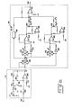
- FIG. 6 illustrates suitable circuitry for the adder 10 and correction generator 14 of FIG. 4 as used in a convergence correction system for a color CRT display.
- Adder 10 includes an operational amplifier 26 receiving at its inverting input a horizontal beam position signal (X) via input terminal 24 and input resistor 28. The non-inverting input of amplifier 26 is referenced to ground potential by resistor 27.
- a feedback resistor 30 paralleled by a capacitor 36 is connected between the output and inverting input of the amplifier.
- a d.c. position shift signal (X ) generated by a potentiometer 32 is applied to the inverting input of amplifier 26 via series resistors 33, 34, whose common junction may be connected to ground via a switch 35.
- the output signal from operational amplifier 26 is of the form (X + X S ).
- the combined signal is indicated simply by X in FIG. 6.
- the position control signal (X ) is controllable by potentiometer 32 to any value required to cancel out delays in the system, or may be disabled by closing switch 35.
- Correction generator 14 includes three multipliers 38, 40, and 42, five differential operational amplifiers 44, 46, 48, 50 and 52, two inverters 54, 56, a variable gain amplifier (or attenuator) 58, two potentiometers 60 and 62, and associated passive elements, which are configured to provide a parabola signal KIX2, and two higher degree correction signals K 2 (X 2 - X 4 ) and K 3 (X - X 3 ). These are, in turn, supplied to the input of summing amplifier 52 to provide the required convergence correction signal from output terminal 64.
- the functions (X - X 4 ) and ( X - X 3 ) are used to provide more precise correction without causing interaction with the parabola signal K 1 X 2 at the right and left sides of the screen.
Landscapes
- Engineering & Computer Science (AREA)
- Multimedia (AREA)
- Signal Processing (AREA)
- Video Image Reproduction Devices For Color Tv Systems (AREA)
- Details Of Television Scanning (AREA)
Applications Claiming Priority (2)
| Application Number | Priority Date | Filing Date | Title |
|---|---|---|---|
| JP49522/81 | 1981-04-03 | ||
| JP56049522A JPS57166776A (en) | 1981-04-03 | 1981-04-03 | Electromagnetic deflecting circuit |
Publications (2)
| Publication Number | Publication Date |
|---|---|
| EP0062529A2 true EP0062529A2 (de) | 1982-10-13 |
| EP0062529A3 EP0062529A3 (de) | 1984-03-21 |
Family
ID=12833463
Family Applications (1)
| Application Number | Title | Priority Date | Filing Date |
|---|---|---|---|
| EP82301796A Withdrawn EP0062529A3 (de) | 1981-04-03 | 1982-04-05 | Verzögerungskompensation in elektromagnetischen Ablenkungssystemen |
Country Status (3)
| Country | Link |
|---|---|
| US (1) | US4623825A (de) |
| EP (1) | EP0062529A3 (de) |
| JP (1) | JPS57166776A (de) |
Cited By (4)
| Publication number | Priority date | Publication date | Assignee | Title |
|---|---|---|---|---|
| DE3510663A1 (de) * | 1984-03-24 | 1985-10-03 | Victor Company Of Japan, Ltd., Yokohama, Kanagawa | Fernsehempfaenger |
| WO1990005428A1 (en) * | 1988-11-08 | 1990-05-17 | Honeywell Inc. | Memory mapped deflection correction system |
| EP0453934A3 (en) * | 1990-04-25 | 1992-03-18 | Deutsche Thomson-Brandt Gmbh | Raster correction device in a television set |
| EP0674431A1 (de) * | 1994-03-24 | 1995-09-27 | Thomson Consumer Electronics, Inc. | Parabelförmiges Signal für Ablenkkorrektur |
Families Citing this family (5)
| Publication number | Priority date | Publication date | Assignee | Title |
|---|---|---|---|---|
| JPH0771195B2 (ja) * | 1987-05-18 | 1995-07-31 | 株式会社日立製作所 | 偏向歪補正回路 |
| US5138238A (en) * | 1991-05-17 | 1992-08-11 | Thomson Consumer Electronics, Inc. | Arrangement for correcting beam landing location error in a video display |
| US5528112A (en) * | 1994-12-08 | 1996-06-18 | Thomson Consumer Electronics, Inc. | Deflection correction signal generator |
| KR0143254B1 (ko) * | 1995-04-28 | 1998-07-15 | 배순훈 | 모니터의 디스토션 보정회로 |
| JP5667172B2 (ja) * | 2009-05-18 | 2015-02-12 | コーニンクレッカ フィリップス エヌ ヴェ | 補間不要な、扇形平行ビーム・リビニング |
Family Cites Families (5)
| Publication number | Priority date | Publication date | Assignee | Title |
|---|---|---|---|---|
| US3501669A (en) * | 1968-11-29 | 1970-03-17 | Bunker Ramo | Deflection signal correction system |
| US3772566A (en) * | 1971-05-07 | 1973-11-13 | Loral Corp | Linearization of magnetically deflected cathode ray tube with non-axial guns |
| US4162434A (en) | 1977-11-07 | 1979-07-24 | Rca Corporation | Regulator with short circuit protection |
| GB2066028A (en) | 1979-12-15 | 1981-07-01 | Ibm | Digitally stored quantities for correction of crt aberrrations |
| US4427926A (en) | 1981-05-18 | 1984-01-24 | Rockwell International Corporation | Dynamic convergence of random scan multi-beam cathode ray tubes |
-
1981
- 1981-04-03 JP JP56049522A patent/JPS57166776A/ja active Granted
-
1982
- 1982-04-05 EP EP82301796A patent/EP0062529A3/de not_active Withdrawn
- 1982-04-05 US US06/365,658 patent/US4623825A/en not_active Expired - Fee Related
Cited By (7)
| Publication number | Priority date | Publication date | Assignee | Title |
|---|---|---|---|---|
| DE3510663A1 (de) * | 1984-03-24 | 1985-10-03 | Victor Company Of Japan, Ltd., Yokohama, Kanagawa | Fernsehempfaenger |
| US4670790A (en) * | 1984-03-24 | 1987-06-02 | Victor Company Of Japan, Ltd. | Television receiver provided with delay circuit |
| WO1990005428A1 (en) * | 1988-11-08 | 1990-05-17 | Honeywell Inc. | Memory mapped deflection correction system |
| EP0453934A3 (en) * | 1990-04-25 | 1992-03-18 | Deutsche Thomson-Brandt Gmbh | Raster correction device in a television set |
| EP0674431A1 (de) * | 1994-03-24 | 1995-09-27 | Thomson Consumer Electronics, Inc. | Parabelförmiges Signal für Ablenkkorrektur |
| EP0674433A1 (de) * | 1994-03-24 | 1995-09-27 | Thomson Consumer Electronics, Inc. | Schleife für die Synchronisation eines parabelförmigen Signals |
| EP0675641A1 (de) * | 1994-03-24 | 1995-10-04 | Thomson Consumer Electronics, Inc. | Amplitudenregelschleife für parabelförmiges Korrektursignal |
Also Published As
| Publication number | Publication date |
|---|---|
| EP0062529A3 (de) | 1984-03-21 |
| JPS57166776A (en) | 1982-10-14 |
| JPS6257146B2 (de) | 1987-11-30 |
| US4623825A (en) | 1986-11-18 |
Similar Documents
| Publication | Publication Date | Title |
|---|---|---|
| US4623825A (en) | Delay compensation in electromagnetic deflection systems | |
| EP0456942B1 (de) | Ablenkjoch mit überlappenden Ablenkspulen | |
| US4500816A (en) | Convergence control apparatus for color cathode ray tube display systems | |
| US4249112A (en) | Dynamic focus and astigmatism correction circuit | |
| US5448140A (en) | Image display apparatus with a deflection circuit having function for correcting rotational distortion | |
| US4766354A (en) | Independent top/bottom pincushion correction | |
| US4707639A (en) | Dynamic focus voltage with phase compensated adjustment | |
| US2869026A (en) | Cathode ray sweep correction system | |
| US4496882A (en) | Inductorless pincushion correction circuit | |
| JPH0422393B2 (de) | ||
| GB2085698A (en) | Stigmator for cathode ray tube | |
| US5367212A (en) | Geometry correction waveform synthesizer | |
| US4524307A (en) | Convergence control system for multigun CRT | |
| EP0059076A1 (de) | Konvergenzregelsystem für eine Mehrstrahlkathodenstrahlröhre | |
| US4501996A (en) | Deflection distortion correcting circuit | |
| US5936363A (en) | User controlled deflection apparatus for correcting upper and lower distortions of a CRT | |
| EP0660364B1 (de) | Anzeigegerät mit Ablenkeinheit | |
| CA1184316A (en) | Colour cathode ray tube display apparatus with compensation for errors due to interfering magnetic fields | |
| US4223252A (en) | Color switching display system | |
| JP3574187B2 (ja) | ビデオ表示用偏向装置 | |
| US4639644A (en) | High voltage dynamic focusing system | |
| JPH0134454Y2 (de) | ||
| JP2907868B2 (ja) | 水平偏向歪自動補正式デイスプレイ | |
| US5091681A (en) | CRT dynamic focus system having independent corner adjustment | |
| JP3031925B2 (ja) | 電磁集束ブラウン管装置 |
Legal Events
| Date | Code | Title | Description |
|---|---|---|---|
| PUAI | Public reference made under article 153(3) epc to a published international application that has entered the european phase |
Free format text: ORIGINAL CODE: 0009012 |
|
| AK | Designated contracting states |
Designated state(s): BE DE GB NL |
|
| PUAL | Search report despatched |
Free format text: ORIGINAL CODE: 0009013 |
|
| AK | Designated contracting states |
Designated state(s): BE DE GB NL |
|
| 17P | Request for examination filed |
Effective date: 19840914 |
|
| STAA | Information on the status of an ep patent application or granted ep patent |
Free format text: STATUS: THE APPLICATION IS DEEMED TO BE WITHDRAWN |
|
| 18D | Application deemed to be withdrawn |
Effective date: 19851010 |
|
| RIN1 | Information on inventor provided before grant (corrected) |
Inventor name: WAHLQUIST, CLAYTON CHARLES Inventor name: OLMSTEAD, HAROLD WAYNE |