EP0062515B1 - Catalytic combustion engines - Google Patents
Catalytic combustion engines Download PDFInfo
- Publication number
- EP0062515B1 EP0062515B1 EP82301764A EP82301764A EP0062515B1 EP 0062515 B1 EP0062515 B1 EP 0062515B1 EP 82301764 A EP82301764 A EP 82301764A EP 82301764 A EP82301764 A EP 82301764A EP 0062515 B1 EP0062515 B1 EP 0062515B1
- Authority
- EP
- European Patent Office
- Prior art keywords
- engine
- catalytic
- combustion chamber
- screens
- chamber
- Prior art date
- Legal status (The legal status is an assumption and is not a legal conclusion. Google has not performed a legal analysis and makes no representation as to the accuracy of the status listed.)
- Expired
Links
- 238000007084 catalytic combustion reaction Methods 0.000 title claims description 5
- 230000003197 catalytic effect Effects 0.000 claims description 46
- 238000002485 combustion reaction Methods 0.000 claims description 32
- 239000000446 fuel Substances 0.000 claims description 20
- 239000007921 spray Substances 0.000 claims description 13
- 230000006835 compression Effects 0.000 claims description 12
- 238000007906 compression Methods 0.000 claims description 12
- 238000002347 injection Methods 0.000 claims description 5
- 239000007924 injection Substances 0.000 claims description 5
- 239000000463 material Substances 0.000 claims description 4
- 239000007788 liquid Substances 0.000 claims description 3
- 239000011819 refractory material Substances 0.000 claims description 2
- 230000013011 mating Effects 0.000 claims 1
- UQMRAFJOBWOFNS-UHFFFAOYSA-N butyl 2-(2,4-dichlorophenoxy)acetate Chemical compound CCCCOC(=O)COC1=CC=C(Cl)C=C1Cl UQMRAFJOBWOFNS-UHFFFAOYSA-N 0.000 description 11
- BASFCYQUMIYNBI-UHFFFAOYSA-N platinum Chemical compound [Pt] BASFCYQUMIYNBI-UHFFFAOYSA-N 0.000 description 7
- 238000005266 casting Methods 0.000 description 5
- 238000010276 construction Methods 0.000 description 5
- 239000003054 catalyst Substances 0.000 description 4
- 239000000919 ceramic Substances 0.000 description 4
- 239000007789 gas Substances 0.000 description 4
- 229910052751 metal Inorganic materials 0.000 description 4
- 239000002184 metal Substances 0.000 description 4
- 229910045601 alloy Inorganic materials 0.000 description 3
- 239000000956 alloy Substances 0.000 description 3
- 238000000034 method Methods 0.000 description 3
- 229910052697 platinum Inorganic materials 0.000 description 3
- PXHVJJICTQNCMI-UHFFFAOYSA-N Nickel Chemical compound [Ni] PXHVJJICTQNCMI-UHFFFAOYSA-N 0.000 description 2
- 239000012634 fragment Substances 0.000 description 2
- 230000003647 oxidation Effects 0.000 description 2
- 238000007254 oxidation reaction Methods 0.000 description 2
- 238000007789 sealing Methods 0.000 description 2
- 239000004215 Carbon black (E152) Substances 0.000 description 1
- 229910000990 Ni alloy Inorganic materials 0.000 description 1
- 229910010293 ceramic material Inorganic materials 0.000 description 1
- 239000003779 heat-resistant material Substances 0.000 description 1
- 229930195733 hydrocarbon Natural products 0.000 description 1
- 150000002430 hydrocarbons Chemical class 0.000 description 1
- 238000011065 in-situ storage Methods 0.000 description 1
- 238000005495 investment casting Methods 0.000 description 1
- 238000002844 melting Methods 0.000 description 1
- 230000008018 melting Effects 0.000 description 1
- 239000000203 mixture Substances 0.000 description 1
- 238000000465 moulding Methods 0.000 description 1
- 229910052759 nickel Inorganic materials 0.000 description 1
- 230000002787 reinforcement Effects 0.000 description 1
- 230000000717 retained effect Effects 0.000 description 1
- 238000010112 shell-mould casting Methods 0.000 description 1
- 239000006104 solid solution Substances 0.000 description 1
Images


Classifications
-
- F—MECHANICAL ENGINEERING; LIGHTING; HEATING; WEAPONS; BLASTING
- F02—COMBUSTION ENGINES; HOT-GAS OR COMBUSTION-PRODUCT ENGINE PLANTS
- F02B—INTERNAL-COMBUSTION PISTON ENGINES; COMBUSTION ENGINES IN GENERAL
- F02B19/00—Engines characterised by precombustion chambers
- F02B19/08—Engines characterised by precombustion chambers the chamber being of air-swirl type
-
- F—MECHANICAL ENGINEERING; LIGHTING; HEATING; WEAPONS; BLASTING
- F02—COMBUSTION ENGINES; HOT-GAS OR COMBUSTION-PRODUCT ENGINE PLANTS
- F02B—INTERNAL-COMBUSTION PISTON ENGINES; COMBUSTION ENGINES IN GENERAL
- F02B19/00—Engines characterised by precombustion chambers
- F02B19/14—Engines characterised by precombustion chambers with compression ignition
-
- F—MECHANICAL ENGINEERING; LIGHTING; HEATING; WEAPONS; BLASTING
- F02—COMBUSTION ENGINES; HOT-GAS OR COMBUSTION-PRODUCT ENGINE PLANTS
- F02B—INTERNAL-COMBUSTION PISTON ENGINES; COMBUSTION ENGINES IN GENERAL
- F02B51/00—Other methods of operating engines involving pretreating of, or adding substances to, combustion air, fuel, or fuel-air mixture of the engines
- F02B51/02—Other methods of operating engines involving pretreating of, or adding substances to, combustion air, fuel, or fuel-air mixture of the engines involving catalysts
-
- F—MECHANICAL ENGINEERING; LIGHTING; HEATING; WEAPONS; BLASTING
- F02—COMBUSTION ENGINES; HOT-GAS OR COMBUSTION-PRODUCT ENGINE PLANTS
- F02M—SUPPLYING COMBUSTION ENGINES IN GENERAL WITH COMBUSTIBLE MIXTURES OR CONSTITUENTS THEREOF
- F02M27/00—Apparatus for treating combustion-air, fuel, or fuel-air mixture, by catalysts, electric means, magnetism, rays, sound waves, or the like
- F02M27/02—Apparatus for treating combustion-air, fuel, or fuel-air mixture, by catalysts, electric means, magnetism, rays, sound waves, or the like by catalysts
-
- F—MECHANICAL ENGINEERING; LIGHTING; HEATING; WEAPONS; BLASTING
- F02—COMBUSTION ENGINES; HOT-GAS OR COMBUSTION-PRODUCT ENGINE PLANTS
- F02B—INTERNAL-COMBUSTION PISTON ENGINES; COMBUSTION ENGINES IN GENERAL
- F02B3/00—Engines characterised by air compression and subsequent fuel addition
- F02B3/06—Engines characterised by air compression and subsequent fuel addition with compression ignition
-
- Y—GENERAL TAGGING OF NEW TECHNOLOGICAL DEVELOPMENTS; GENERAL TAGGING OF CROSS-SECTIONAL TECHNOLOGIES SPANNING OVER SEVERAL SECTIONS OF THE IPC; TECHNICAL SUBJECTS COVERED BY FORMER USPC CROSS-REFERENCE ART COLLECTIONS [XRACs] AND DIGESTS
- Y02—TECHNOLOGIES OR APPLICATIONS FOR MITIGATION OR ADAPTATION AGAINST CLIMATE CHANGE
- Y02T—CLIMATE CHANGE MITIGATION TECHNOLOGIES RELATED TO TRANSPORTATION
- Y02T10/00—Road transport of goods or passengers
- Y02T10/10—Internal combustion engine [ICE] based vehicles
- Y02T10/12—Improving ICE efficiencies
Definitions
- This invention relates to reciprocating-piston internal combustion engines of the type which employs a catalyst in the or each combustion chamber to initiate and promote combustion at the compression temperature in the chamber.
- Such engines are referred to herein as catalytic combustion engines.
- Our prior patent application GB-A-2 057 563 relates to a catalytic combustion engine without spark ignition, provided in its cylinder head or heads with a precombustion chamber associated with each cylinder and connected with the space in the cylinder above the piston crown via a transfer passage so disposed as to promote swirl in the precombustion chamber during the compression stroke of the associated piston, and injector means for injecting a spray of liquid fuel into the precombustion chamber shortly before top-dead-centre, the air for combustion being admitted directly into the main combustion space in the cylinder, and which is further provided with a catalytic element mounted in the pre- combustion chamber.
- a catalytic screen e.g.
- gauze extends completely across the interior of the precombustion chamber, below its domed upper portion machined in the cylinder head, the gauze extending at right angles to the axis of reciprocation of the piston in the associated cylinder in a position between the fuel injection nozzle and the mouth of the transfer passage which connects the interior of the precombustion chamber with the cylinder space above the piston.
- a gas-permeable catalytic screen for example gauze
- the catalytic element comprises at least one foraminous screen member, for example a grid, mesh or gauze, mounted to enclose a segment of the interior of the precombustion chamber and lying on one side of the plane of symmetry (AA) of the precombustion chamber, without intersecting the circumferential swirl path (Y) around the interior of the chamber of the air forced into the chamber through the transfer passage during the compression stroke.
- AA plane of symmetry
- a pair of catalytic screen members e.g. gauzes, may be provided in each pre- combustion chamber, the members respectively enclosing segments of its interior on opposite sides of the mouth of the transfer passage and injector nozzle, the minimum spacing between the two catalytic screen members being greater than the width of the mouth of the transfer passage.
- the pair of catalytic screens comprise generally planar parallel screens, e.g. gauzes, which are disposed in a symmetrical arrangement with respect to and parallel to the longitudinal axis of the transfer passage.
- the screens will lie parallel to the cylinder bore axis, the axis of the transfer passage being oblique to the cylinder bore axis and the passage entering the precombustion chamber generally tangentially.
- an unimpeded circumferential swirl path is provided around the interior of the precombustion chamber between the parallel screens, into which the fuel is sprayed by the injector means. It may be found preferable for the injector to be arranged so that the injected fuel spray just brushes one or each of the screens.
- the fuel injector axis can be preset with respect to the cylinder bore axis, at any preferred angle between the perpendicular and the parallel thereto, as required to optimise injection variables with maximum engine performance.
- each cylinder 10 of a multi-cylinder reciprocating piston i.c. engine has a precombustion chamber 11 containing catalytic elements 37 formed in its cylinder head 12 and communicating through a passage 13 (referred to as the transfer passage) with the clearance volume 14 within the cylinder 10 above the crown of the associated piston 15.
- the engine is of the air-compressing piston type constructed and operated on generally similar principles to a conventional Diesel engine, i.e. without any spark ignition, but the mixture of injected fuel and compressed air are ignited catalytically in the precombustion chamber under the prevailing compression pressure at around top-dead centre, the subsequent combustion being promoted by the catalyst.
- Each pre- combustion chamber 11 is of the Ricardo Comet Mark V form (see British patent specification No. 786,329) and has a hemispherical "upper" part 16 remote from the cylinder 10, merging into a short cylindrical intermediate portion 17, the "lower” portion 18 of the precombustion chamber 11 being of mainly frusto-conical form tapering towards the cylinder 10 and having a flat bottom wall 19.
- the axis 13A of the transfer passage 13 is inclined to the bore axis of the cylinder 10 and opens through the flat bottom 19 of the chamber in a generally "tangential" disposition with respect to the internal surface of the chamber 11, so that during each compression stroke of the piston 15 air charge previously admitted to the cylinder 10 will be forced under pressure through the transfer passage 13 and will enter the pre- combustion chamber tangentially thus setting up a swirl around the chamber 11 in the direction indicated by the arrow Y in Figure 1A, the swirl path being around an axis at right angles to the direction of reciprocation of the piston 15 (indicated by arrow X) and to the axis 13A of the passage 13 and parallel to the flat bottom 19 of the chamber 11.
- a fuel injector is housed in a recess 20 formed in the cylinder head 12 to inject a spray of liquid hydrocarbon fuel through an aperture 21 formed in the upper part of the hemispherical upper portion 16 of the chamber 11, the axis of injection 22 being inclined at a predetermined angle to the "vertical" axis of symmetry 23 of the chamber 11, which it intersects at a point C above the centre O of the domed upper portion 16 of the chamber 11 as shown in the drawings.
- the fuel spray is injected generally tangentially and downstream into the swirling gas travelling around the interior of the chamber 11.
- An electrical heater (or glow) plug 24 projects “horizontally' into the interior of the chamber through a recess 25 in the side of the chamber 11, its axis 24A intersecting the axis 23 between the points C and O.
- each precombustion chamber 11 is formed in a separate shell member 30 which is a close fit in a corresponding recess 31 machined in the cylinder head 12, and located by an integral circumferential flange 33 against a step 34 in the cylinder head recess 31.
- Two side wall plugs 35 are inserted as a light press fit into recesses 36 formed in opposite side walls of the shell member 30, the internal surfaces of the shell member 30 and the two side wall plugs 35 together defining the internal shape of the pre- combustion chamber 11.
- the plugs 35 are retained by engagement against the wall of the recess 31 in the cylinder head when the shell member and plugs are fitted into that recess.
- the shell member 30 and the two side wall plugs are precision castings of a suitable heat-resistant material, for example the nickel alloy sold under the trade name NIMOCAST.
- the two side wall plugs 35 are used to clamp the margins of a pair of respective circular catalytic screens 37 against circumferential steps 38 which terminate the recesses 36 in opposite sides of the shell member 30.
- the catalytic screens 37 are plane parallel circular sheets of gauze, with suitable wire reinforcement.
- each gauze 37 may be a circular disc made of metallic platinum or other catalytic metal wire and be supported on a frame of stronger wire.
- it may comprise a thicker mesh or porous screen made of non- catalytic metal or ceramic material coated with an appropriate base ceramic wash on which a suitable oxidation catalyst is deposited by means well known in the relevant art.
- the sealing of the injector and of the heater plug 24 will be effected in the cylinder head, although if desired sealing against the combustion chamber wall can be effected by well-known but more complicated methods.
- the two parallel catalytic gauzes lie one on either side of the mouth of the transfer passage 13, with the inclined axis 13A of the latter being also parallel to the gauzes, so that the flow of air injected through the passage 13 on each compression stroke will be free to circulate around the internal circumference of the precombustion chamber 11 without the gauzes projecting into or across its circumferential swirl path.
- the injector nozzle injects the fuel spray into the space between the parallel gauzes, and hence into the swirl path of the circulating air flow, in the downstream tangential direction along an axis parallel to the gauzes and midway between them, the spray of fuel being preferably arranged just to brush the gauzes.
- the angle of inclination of the axis 22 of injection to the "vertical" axis of symmetry 23 of the chamber 11 can be predetermined as required for maximum engine performance.
- the heater plug 24 also projects into the space between the gauzes 37, in a position in which a portion of the injected fuel spray will impinge upon it.
- the two catalytic gauzes 37 are positively clamped between the plugs 35 and the steps 36 of the shell member 30, around their entire peripheries.
- the gauzes are circular in profile and are arranged parallel to one another and to the "vertical" axis of symmetry 23 of the chamber 11. If desired however the arrangement could be modified so as to clamp the gauzes in a symmetrical arrangement inclined at small equal angles to the axis 23, provided they do not intrude substantially into the swirl path of the circulating air.
- FIGS 2A and 2B show a modified arrangement in which a one-piece precombustion chamber shell 40 is used and the gauzes 41 are located in parallel slits 42 formed in the shell 40.
- the whole shell 40 including the flanged base is precision-cast as an integral unit using the lost-wax shell moulding technique or a ceramic core method of moulding, and is inserted as a whole in the recess 31 machined in the cylinder head 12, and is located by the bottom flange 33.
- the clearance between the exterior of the shell 40 and the interior of the recess 33 is arranged to be as small as possible, and suitable holes 21 and 25 are precast in the shell 40 to receive the fuel injector nozzle and the heater plug in the same positions as in Figures 1A and 1 B.
- the fuel injector 21 and heater (glow) plug 24 are located and gas-sealed in the usual way in the cast exterior cylinder head structure.
- the catalytic screens 41 Whilst it would theoretically be possible for the catalytic screens 41 to be cast in situ in the shell 40 in their appropriate positions during the casting of the shell itself, there are difficulties in doing so in practice in that the gauze or other screens would have to be made of material which will neither melt nor dissolve when the molten casting material to form the shell 40 is poured into the mould in which the screens have been positioned. If the screens are made for example of platinum, this metal has a higher melting point than the typical NIMOCAST or similar heat-resistant alloy used to cast the shell 40, but since the casting alloy contains nickel with which platinum can form a solid solution it is likely that the platinum gauzes would be dissolved in the molten alloy during the casting.
- the shell 40 after casting is formed with a pair of parallel slits 42 spaced apart on either side of the mouth of the transfer passage 13 and parallel to the axes 13A and 23, each slit extending from the top of the domed upper portion of the shell 40 down to or (as shown) slightly below the surface of the flat bottom 19 of the precombustion chamber 11.
- the two catalytic screens 41 are fully inserted in the respective slits 42, wherein they will be positively located when the shell 40 is inserted into the cylinder head recess 31.
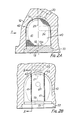
- Figures 3A and 3B show another embodiment of the invention, in which the upper part of the precombustion chamber is defined by the internal surface of the upper part of a recess 50 machined directly in the cylinder head 12, to form the hemi- spherical upper surface 16 and the intermediate cylindrical surface 17 of the chamber as machined surfaces, whilst the tapered lower portion 18 and bottom 19 of the chamber 11 are formed by a recess in a separate "hot plug" 51 made of refractory material which is inserted into the correspondingly-shaped lower part of the recess 50 and located by its bottom flange 52, as is well- p known practice for a Comet-type precombustion chamber.
- a separate "hot plug" 51 made of refractory material which is inserted into the correspondingly-shaped lower part of the recess 50 and located by its bottom flange 52, as is well- p known practice for a Comet-type precombustion chamber.
- the catalytic screens 55 in this case form part of a dumb-bell-shaped insert assembly 56 comprising a rod 57 which extends across the chamber 11, upon which rod the two screens 55 are mounted at their required spacing, the rod 57 extending through mounting apertures in the screens 55 and at right angles thereto.
- the two end portions of the rod are formed with flats 58 and rest in hemi-cylindrical notches in the rim of the hot plug 51 where they are trapped by a step in the machined recess 50 in the head 12, as shown in Figure 3B, and the two catalytic screens 55 are profiled to abut the internal surface of the chamber 11 around their entire peripheries, one on either side of the mouth of the transfer passage 13 formed in the hot plug 51.
- the catalytic screens are mounted in spaced parallel positions and lie parallel to the inclined axis of the transfer passage 13 and to the inclined spray axis 22, as before, as well as being parallel to the "vertical" axis of symmetry 23 of the precombustion chamber 11.
- each catalytic screen 55 may comprise a metallic catalytic gauze supported for strength by a stiff outer rim 58 and radial spokes 59, of stout metal wire or strip, with a central wire or strip hub 60 through which the rod 57 extends.
- each screen 55 could be of a thicker foraminous metallic or even ceramic screen material coated with a base ceramic wash on which a suitable oxidation catalyst layer is deposited by known means.
- the catalytic screens may be slightly inclined to the axis of symmetry 23 of the precombustion chamber 11, provided that they do not intrude significantly into the circumferential air swirl path around the chamber.
- the spacing between the catalytic screens where they are parallel, or the minimum spacing where they are inclined to one another should preferably exceed the width of the transfer passage 13 at its throat, which is normally about 0.45 times the maximum diameter of the precombustion chamber.
- the precise spacing between the screens may be determined by trial and error to optimise results. It is likely that this spacing should be between 0.35D and 0.60D where D is the diameter of the hemispherical upper portion 16 of the pre- combustion chamber shell.
- At least a part of the injected fuel spray should brush against the two catalytic gauzes in each case, and that the heater plug should be so positioned that a part of the fuel spray impinges on it.
- Each of the specific embodiments described and illustrated will operate by catalytic self-ignition and combustion at a very much lower compression ratio than that required for a diesel engine without catalytic ignition, which is around 21.1:1.
- the illustrated arrangement will operate satisfactorily at a compression ratio very much lower than 21.1:1 and down to around 12:1, which as explained in our aforesaid application No. GB-A-2 057 563 is the theoretically- optimum compression ratio for an I.C. engine as regards brake horsepower output.
- twin "vertical” or near-"vertical” catalytic screens provided in each of the illustrated embodiments is found to enable a greater maximum power output to be produced in certain circumstances than is possible with a similar engine having the "horizontal" catalytic screen arrangement of our application GB-A-2 057 563.
Landscapes
- Engineering & Computer Science (AREA)
- Chemical & Material Sciences (AREA)
- Combustion & Propulsion (AREA)
- Mechanical Engineering (AREA)
- General Engineering & Computer Science (AREA)
- Chemical Kinetics & Catalysis (AREA)
- Combustion Methods Of Internal-Combustion Engines (AREA)
Applications Claiming Priority (2)
| Application Number | Priority Date | Filing Date | Title |
|---|---|---|---|
| GB8110389 | 1981-04-02 | ||
| GB8110389 | 1981-04-02 |
Publications (3)
| Publication Number | Publication Date |
|---|---|
| EP0062515A2 EP0062515A2 (en) | 1982-10-13 |
| EP0062515A3 EP0062515A3 (en) | 1983-11-16 |
| EP0062515B1 true EP0062515B1 (en) | 1986-02-26 |
Family
ID=10520867
Family Applications (1)
| Application Number | Title | Priority Date | Filing Date |
|---|---|---|---|
| EP82301764A Expired EP0062515B1 (en) | 1981-04-02 | 1982-04-02 | Catalytic combustion engines |
Country Status (8)
| Country | Link |
|---|---|
| US (1) | US4425884A (OSRAM) |
| EP (1) | EP0062515B1 (OSRAM) |
| JP (1) | JPS5813121A (OSRAM) |
| CA (1) | CA1199243A (OSRAM) |
| DE (1) | DE3269292D1 (OSRAM) |
| ES (1) | ES511068A0 (OSRAM) |
| GB (1) | GB2097059B (OSRAM) |
| ZA (1) | ZA822254B (OSRAM) |
Families Citing this family (10)
| Publication number | Priority date | Publication date | Assignee | Title |
|---|---|---|---|---|
| US4811707A (en) * | 1981-03-30 | 1989-03-14 | Pfefferle William C | Method of operating catalytic ignition engines and apparatus therefor |
| FR2543617B1 (fr) * | 1983-03-29 | 1985-07-12 | Renault | Culasse pour moteurs a combustion a allumage par compression |
| ES2040246T3 (es) * | 1986-02-25 | 1993-10-16 | Coventry University | Motor de combustion interna. |
| CA1329780C (en) * | 1988-05-07 | 1994-05-24 | Dan Merritt | Internal combustion engine |
| IT1235594B (it) * | 1989-09-12 | 1992-09-11 | Vm Motori Spa | Precamera di combustione per motori ad accensione per compressione |
| US5136994A (en) * | 1991-04-15 | 1992-08-11 | Southwest Research Institute | Internal combustion engine |
| US5307772A (en) * | 1992-12-16 | 1994-05-03 | Ford Motor Company | Redox catalysis of NOx in internal combustion engines |
| EP0975033A4 (en) * | 1997-01-31 | 2006-05-24 | Sanyo Electric Co | HYDROGEN SAUCE POWDER AND METHOD FOR THE PRODUCTION THEREOF |
| AR022855A1 (es) * | 2000-03-07 | 2002-09-04 | Brardinelli Juan Ignacio | El uso de un catalizador interno para motores diesel |
| US20040097836A1 (en) * | 2000-10-06 | 2004-05-20 | Ombrellaro Mark P. | Direct manual examination of remote patient with virtual examination functionality |
Family Cites Families (12)
| Publication number | Priority date | Publication date | Assignee | Title |
|---|---|---|---|---|
| US455329A (en) | 1891-07-07 | Stringed musical instrument | ||
| FR549134A (fr) * | 1921-05-23 | 1923-02-02 | Injecteur-carburateur pour moteur de grande puissance à huiles lourdes | |
| GB439426A (en) | 1934-06-06 | 1935-12-06 | Harry Ralph Ricardo | Improvements in or relating to internal combustion engines of the liquid-fuel injection compression-ignition type |
| US2513874A (en) | 1945-09-22 | 1950-07-04 | Howard Arthur Clifford | Combustion chamber for compression ignition internal-combustion engines |
| US2821177A (en) | 1954-10-11 | 1958-01-28 | Ricardo & Co Engineers | Internal combustion engines of the compression ignition type |
| DE2430983A1 (de) * | 1973-07-12 | 1975-01-30 | Inst Ciezkiej Syntezy Orga | Verbrennungsmotor, der verbrennungsgase mit erniedrigtem gehalt an toxischen bestandteilen emittiert |
| GB1578027A (en) | 1976-06-10 | 1980-10-29 | Ricardo Consulting Engs Ltd | Ic engines having catalytic ignition |
| JPS5486008A (en) * | 1977-12-19 | 1979-07-09 | Nissan Motor Co Ltd | Eddy current chamber type diesel engine |
| DE2804562A1 (de) * | 1978-02-03 | 1979-08-09 | Volkswagenwerk Ag | Mehrzylindrige brennkraftmaschine |
| GB2039612B (en) * | 1979-01-10 | 1983-09-28 | Johnson Matthey Co Ltd | Ic engine with catalytic ignition |
| DE2919743A1 (de) | 1979-05-16 | 1980-11-27 | Volkswagenwerk Ag | Brennraum fuer brennkraftmaschinen |
| GB2057563B (en) | 1979-08-23 | 1983-10-26 | Ricardo Consulting Engs Ltd | Catalytic combustion engines |
-
1982
- 1982-04-01 ES ES511068A patent/ES511068A0/es active Granted
- 1982-04-01 ZA ZA822254A patent/ZA822254B/xx unknown
- 1982-04-01 CA CA000400355A patent/CA1199243A/en not_active Expired
- 1982-04-01 US US06/364,306 patent/US4425884A/en not_active Expired - Fee Related
- 1982-04-02 DE DE8282301764T patent/DE3269292D1/de not_active Expired
- 1982-04-02 JP JP57053983A patent/JPS5813121A/ja active Granted
- 1982-04-02 GB GB8209803A patent/GB2097059B/en not_active Expired
- 1982-04-02 EP EP82301764A patent/EP0062515B1/en not_active Expired
Also Published As
| Publication number | Publication date |
|---|---|
| ES8304261A1 (es) | 1983-02-16 |
| ZA822254B (en) | 1983-11-30 |
| DE3269292D1 (en) | 1986-04-03 |
| JPS5813121A (ja) | 1983-01-25 |
| EP0062515A2 (en) | 1982-10-13 |
| GB2097059B (en) | 1984-09-12 |
| GB2097059A (en) | 1982-10-27 |
| JPS6212369B2 (OSRAM) | 1987-03-18 |
| EP0062515A3 (en) | 1983-11-16 |
| ES511068A0 (es) | 1983-02-16 |
| CA1199243A (en) | 1986-01-14 |
| US4425884A (en) | 1984-01-17 |
Similar Documents
| Publication | Publication Date | Title |
|---|---|---|
| EP0062515B1 (en) | Catalytic combustion engines | |
| SU1080754A3 (ru) | Двигатель внутреннего сгорани | |
| US4939984A (en) | Investment-cast piston crown cap with encapsulated non-metallic insulating core | |
| US6098588A (en) | Injection device and combustion process for an internal combustion engine | |
| US4086763A (en) | Thermal reactor system for internal combustion engine | |
| US5483933A (en) | Combustion chamber structure for diesel engines | |
| JPH04272425A (ja) | ディーゼルエンジンの燃焼室 | |
| US5515823A (en) | Engine with precombustion chambers | |
| JPS6236133B2 (OSRAM) | ||
| EP0780554B1 (en) | Piston structure with heat insulated combustion chamber | |
| KR100199808B1 (ko) | 실린더헤드의 주조금형 | |
| CN1823213B (zh) | 燃料喷射系统 | |
| JPS63176621A (ja) | 内燃機関の燃焼室構造 | |
| JPS6145294Y2 (OSRAM) | ||
| JP3861319B2 (ja) | 筒内直噴式内燃機関 | |
| SU1657689A1 (ru) | Двигатель внутреннего сгорани с воспламенением от сжати | |
| JP2562423Y2 (ja) | グロープラグ | |
| JP2853209B2 (ja) | 副室断熱エンジン | |
| JPH0842344A (ja) | 副燃焼室を持つピストンの構造 | |
| JPH036824Y2 (OSRAM) | ||
| JPH0238026Y2 (OSRAM) | ||
| JPH03168322A (ja) | 直噴式断熱ディーゼルエンジンの燃焼室 | |
| JP2522799Y2 (ja) | 直噴式ディーゼル機関の燃焼室 | |
| JPH09170436A (ja) | 遮熱燃焼室付きピストンの構造 | |
| JPS5852327Y2 (ja) | 内燃機関の燃焼室構造 |
Legal Events
| Date | Code | Title | Description |
|---|---|---|---|
| PUAI | Public reference made under article 153(3) epc to a published international application that has entered the european phase |
Free format text: ORIGINAL CODE: 0009012 |
|
| AK | Designated contracting states |
Designated state(s): DE FR IT NL |
|
| 17P | Request for examination filed |
Effective date: 19830330 |
|
| PUAL | Search report despatched |
Free format text: ORIGINAL CODE: 0009013 |
|
| AK | Designated contracting states |
Designated state(s): DE FR IT NL |
|
| RBV | Designated contracting states (corrected) |
Designated state(s): DE FR IT NL |
|
| GRAA | (expected) grant |
Free format text: ORIGINAL CODE: 0009210 |
|
| ITF | It: translation for a ep patent filed | ||
| AK | Designated contracting states |
Designated state(s): DE FR IT NL |
|
| REF | Corresponds to: |
Ref document number: 3269292 Country of ref document: DE Date of ref document: 19860403 |
|
| ET | Fr: translation filed | ||
| PLBE | No opposition filed within time limit |
Free format text: ORIGINAL CODE: 0009261 |
|
| STAA | Information on the status of an ep patent application or granted ep patent |
Free format text: STATUS: NO OPPOSITION FILED WITHIN TIME LIMIT |
|
| 26N | No opposition filed | ||
| ITTA | It: last paid annual fee | ||
| PGFP | Annual fee paid to national office [announced via postgrant information from national office to epo] |
Ref country code: NL Payment date: 19910430 Year of fee payment: 10 |
|
| PGFP | Annual fee paid to national office [announced via postgrant information from national office to epo] |
Ref country code: FR Payment date: 19920408 Year of fee payment: 11 |
|
| PGFP | Annual fee paid to national office [announced via postgrant information from national office to epo] |
Ref country code: DE Payment date: 19920514 Year of fee payment: 11 |
|
| PG25 | Lapsed in a contracting state [announced via postgrant information from national office to epo] |
Ref country code: NL Effective date: 19921101 |
|
| NLV4 | Nl: lapsed or anulled due to non-payment of the annual fee | ||
| PG25 | Lapsed in a contracting state [announced via postgrant information from national office to epo] |
Ref country code: FR Effective date: 19931229 |
|
| PG25 | Lapsed in a contracting state [announced via postgrant information from national office to epo] |
Ref country code: DE Effective date: 19940101 |
|
| REG | Reference to a national code |
Ref country code: FR Ref legal event code: ST |