EP0062437A2 - Streifenbelichtungssystem - Google Patents
Streifenbelichtungssystem Download PDFInfo
- Publication number
- EP0062437A2 EP0062437A2 EP82301465A EP82301465A EP0062437A2 EP 0062437 A2 EP0062437 A2 EP 0062437A2 EP 82301465 A EP82301465 A EP 82301465A EP 82301465 A EP82301465 A EP 82301465A EP 0062437 A2 EP0062437 A2 EP 0062437A2
- Authority
- EP
- European Patent Office
- Prior art keywords
- strip
- platen
- reflectors
- reflector
- illumination system
- Prior art date
- Legal status (The legal status is an assumption and is not a legal conclusion. Google has not performed a legal analysis and makes no representation as to the accuracy of the status listed.)
- Granted
Links
- 238000005286 illumination Methods 0.000 title claims abstract description 39
- 238000003384 imaging method Methods 0.000 claims description 8
- 239000013589 supplement Substances 0.000 claims 1
- 230000003287 optical effect Effects 0.000 description 4
- 238000003491 array Methods 0.000 description 2
- 239000011248 coating agent Substances 0.000 description 2
- 238000000576 coating method Methods 0.000 description 2
- 238000010586 diagram Methods 0.000 description 2
- PCTMTFRHKVHKIS-BMFZQQSSSA-N (1s,3r,4e,6e,8e,10e,12e,14e,16e,18s,19r,20r,21s,25r,27r,30r,31r,33s,35r,37s,38r)-3-[(2r,3s,4s,5s,6r)-4-amino-3,5-dihydroxy-6-methyloxan-2-yl]oxy-19,25,27,30,31,33,35,37-octahydroxy-18,20,21-trimethyl-23-oxo-22,39-dioxabicyclo[33.3.1]nonatriaconta-4,6,8,10 Chemical compound C1C=C2C[C@@H](OS(O)(=O)=O)CC[C@]2(C)[C@@H]2[C@@H]1[C@@H]1CC[C@H]([C@H](C)CCCC(C)C)[C@@]1(C)CC2.O[C@H]1[C@@H](N)[C@H](O)[C@@H](C)O[C@H]1O[C@H]1/C=C/C=C/C=C/C=C/C=C/C=C/C=C/[C@H](C)[C@@H](O)[C@@H](C)[C@H](C)OC(=O)C[C@H](O)C[C@H](O)CC[C@@H](O)[C@H](O)C[C@H](O)C[C@](O)(C[C@H](O)[C@H]2C(O)=O)O[C@H]2C1 PCTMTFRHKVHKIS-BMFZQQSSSA-N 0.000 description 1
- 230000000694 effects Effects 0.000 description 1
- 238000000034 method Methods 0.000 description 1
- 239000013307 optical fiber Substances 0.000 description 1
- 108091008695 photoreceptors Proteins 0.000 description 1
- 239000007787 solid Substances 0.000 description 1
Images

Classifications
-
- H—ELECTRICITY
- H04—ELECTRIC COMMUNICATION TECHNIQUE
- H04N—PICTORIAL COMMUNICATION, e.g. TELEVISION
- H04N1/00—Scanning, transmission or reproduction of documents or the like, e.g. facsimile transmission; Details thereof
- H04N1/024—Details of scanning heads ; Means for illuminating the original
- H04N1/028—Details of scanning heads ; Means for illuminating the original for picture information pick-up
- H04N1/02815—Means for illuminating the original, not specific to a particular type of pick-up head
- H04N1/02845—Means for illuminating the original, not specific to a particular type of pick-up head using an elongated light source, e.g. tubular lamp, LED array
- H04N1/0285—Means for illuminating the original, not specific to a particular type of pick-up head using an elongated light source, e.g. tubular lamp, LED array in combination with at least one reflector which is in fixed relation to the light source
-
- G—PHYSICS
- G02—OPTICS
- G02B—OPTICAL ELEMENTS, SYSTEMS OR APPARATUS
- G02B19/00—Condensers, e.g. light collectors or similar non-imaging optics
- G02B19/0004—Condensers, e.g. light collectors or similar non-imaging optics characterised by the optical means employed
- G02B19/0028—Condensers, e.g. light collectors or similar non-imaging optics characterised by the optical means employed refractive and reflective surfaces, e.g. non-imaging catadioptric systems
-
- G—PHYSICS
- G02—OPTICS
- G02B—OPTICAL ELEMENTS, SYSTEMS OR APPARATUS
- G02B19/00—Condensers, e.g. light collectors or similar non-imaging optics
- G02B19/0033—Condensers, e.g. light collectors or similar non-imaging optics characterised by the use
- G02B19/0085—Condensers, e.g. light collectors or similar non-imaging optics characterised by the use for use with both a detector and a source
-
- G—PHYSICS
- G03—PHOTOGRAPHY; CINEMATOGRAPHY; ANALOGOUS TECHNIQUES USING WAVES OTHER THAN OPTICAL WAVES; ELECTROGRAPHY; HOLOGRAPHY
- G03B—APPARATUS OR ARRANGEMENTS FOR TAKING PHOTOGRAPHS OR FOR PROJECTING OR VIEWING THEM; APPARATUS OR ARRANGEMENTS EMPLOYING ANALOGOUS TECHNIQUES USING WAVES OTHER THAN OPTICAL WAVES; ACCESSORIES THEREFOR
- G03B27/00—Photographic printing apparatus
- G03B27/32—Projection printing apparatus, e.g. enlarger, copying camera
- G03B27/52—Details
- G03B27/54—Lamp housings; Illuminating means
- G03B27/542—Lamp housings; Illuminating means for copying cameras, reflex exposure lighting
-
- H—ELECTRICITY
- H04—ELECTRIC COMMUNICATION TECHNIQUE
- H04N—PICTORIAL COMMUNICATION, e.g. TELEVISION
- H04N1/00—Scanning, transmission or reproduction of documents or the like, e.g. facsimile transmission; Details thereof
- H04N1/024—Details of scanning heads ; Means for illuminating the original
- H04N1/028—Details of scanning heads ; Means for illuminating the original for picture information pick-up
- H04N1/02815—Means for illuminating the original, not specific to a particular type of pick-up head
- H04N1/02845—Means for illuminating the original, not specific to a particular type of pick-up head using an elongated light source, e.g. tubular lamp, LED array
- H04N1/0287—Means for illuminating the original, not specific to a particular type of pick-up head using an elongated light source, e.g. tubular lamp, LED array using a tubular lamp or a combination of such lamps
Definitions
- This invention relates to a document illumination system and more particularly to a pair of reflector elements placed on opposite sides of an optical slit so as to direct illumination towards the slit.
- Prior art illumination systems for line-by-line scanning of a document have provided a plurality of lamp and reflector combinations.
- the simplest arrangement consists of an elongated lamp located so as to direct the light emanating through an aperture onto a scan strip.
- reflectors either behind, or partially enveloping, the lamp to increase illumination of the scanning area is also well known.
- an apertured light source is located adjacent an object plane to be scanned, a first reflector is located on the opposite side of the scan strip and a second reflector is placed on the same side of the exposure zone as the illumination source and between the source and the object plane.
- These reflectors effectively capture all of the solid angle of light subtended from the illumination source.
- the reflectors are of the facetted type and are arranged in a platenless constant velocity transport (CVT) system.
- the reflectors are used in an arrangement wherein the document to be copied is supported on a platen and the two reflectors are modified to extend into the envelope of the platen.
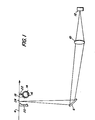
- FIG. 1 illustrates a first embodiment of the invention wherein a illumination system, indicated generally as 2, illuminates a document 4 moving in an object plane in the indicated direction.
- This system is commonly referred to as a constant velocity transport (CVT) system and the absence of a platen permits the close positioning of illumination source and reflectors to the document as described below.
- An image of each incrementally scanned line is reflected at;mirror 6, and projected by lens 10 onto photosensor array 12 located in an imaging plane.
- the illumination system 2 comprises a linear lamp 14 which can be a fluorescent lamp with a reflective coating 16 on the lamp envelope. The coating is omitted from a portion of the envelope so that a clear longitudinal aperture 18 subtending 45° is formed.
- a pair of facetted reflectors 20, 22 is located on either side of exposure zone 24 and serve to direct illumination from lamp 16 onto narrow longitudinal exposure zone 24 in a manner discussed in greater detail below. It should be appreciated that elements 14, 20, 22 are shown in end view and that their lengths extend perpendicular to the plane of the page thereby incrementally illuminating lines of information on the document as it passes through the exposure zone.
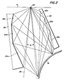
- reflectors 20 and 22 each comprise a rigidly connected set of plane mirrors (facets) 20a, 20b, 20c, 22a, 22b, 22c.
- the reflectors 2 may be constructed as described in the aforementioned patent 4,190,355.
- Each facet 20a, 20b, 20c of reflector 20 is set at an angle and is of such a length that the entire aperture 18 of lamp 14 is visible from exposure strip 24.
- a similar procedure is followed for reflector 22.
- the above described system is thus seen to maximize the illumination from the relatively low radiance fluorescent source. In the absence of any reflectors, the radiometric efficiency of the scanner would be extremely poor. If a first reflector 20 is added, the gain is increased by about 1.9x, the gain being defined as the ratio of the irradiance at the exposure slit produced by the lamp and reflector, to the irradiance at the exposure slit produced by a lamp only, of the same diameter, at the same distance from the exposure slit and at the lamp's optimum aperture orientation angle and aperture size. With the addition of reflector 22, the gain increases to 2.6. Because of the symmetrical arrangement of the two reflectors, there is also a good light "balance" in the left/right input. This balance helps to reduce 'paste-up' shadows.
- either or both reflectors may have a curved surface. The reflectors would still be positioned relative to the aperture so that their surfaces capture the light leaving the lamp aperture.
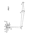
- FIG. 3 the present invention is shown modified for use in a system wherein document 4 is moved across the surface of a platen 40.
- a fluorescent lamp 42 in conjunction with facetted reflectors 44, 46, direct light towards exposure zone 48. Since the platen has a finite thickness, however, the reflectors are separated from the documents by the thickness of the platen, typically 6-12mm. This arrangement, although acceptable for some systems, would result in somewhat less radiometric efficiency of the photosensor since some light from the lamp would be let through the areas of the platen above and to the sides of the reflector.
- reflectors 44, 46 have been effectively extended by inserting additional reflective elements 44a, 46a into the body of the platen.
- these elements form a trapezoidal cross-section ABCD and are so arranged that each point along the surface is totally internally reflecting light from lamp onto the exposure strip.
- the elements 44a, 46a are flat, they can also be curved, as can portion BC of the platen. These curved embodiments add additional power to the configuration and increase efficiency even further. Also, for a simpler system, one of the elements 44a, 46a may be omitted thereby incurring some loss of efficiency. For some systems, the economical tradeoff may be acceptable.
- Figures 1 and 3 show images being projected onto a photosensor, other imaging surfaces may be used.
- the reflected images may be projected onto a photoreceptor in either drum or belt form as is known in the art.
- Another exemplary application of the disclosed illumination system is in conjunction with the use of a linear lens such as a SELFOC lens array comprising a plurality of gradient index optical fibers.
- SELFOC lens array comprising a plurality of gradient index optical fibers.
- the operations of these lens arrays in a copier environment require an intense narrow band illumination of the document to be copied and the disclosed lamp/ reflectors provide this type of illumination.
Landscapes
- Physics & Mathematics (AREA)
- Engineering & Computer Science (AREA)
- Multimedia (AREA)
- Signal Processing (AREA)
- General Physics & Mathematics (AREA)
- Optics & Photonics (AREA)
- Light Sources And Details Of Projection-Printing Devices (AREA)
- Exposure Or Original Feeding In Electrophotography (AREA)
- Optical Systems Of Projection Type Copiers (AREA)
- Holders For Sensitive Materials And Originals (AREA)
Applications Claiming Priority (2)
| Application Number | Priority Date | Filing Date | Title |
|---|---|---|---|
| US06/249,058 US4396834A (en) | 1981-03-30 | 1981-03-30 | Dual reflector illumination system |
| US249058 | 1999-02-12 |
Publications (3)
| Publication Number | Publication Date |
|---|---|
| EP0062437A2 true EP0062437A2 (de) | 1982-10-13 |
| EP0062437A3 EP0062437A3 (en) | 1982-12-22 |
| EP0062437B1 EP0062437B1 (de) | 1985-10-02 |
Family
ID=22941885
Family Applications (1)
| Application Number | Title | Priority Date | Filing Date |
|---|---|---|---|
| EP82301465A Expired EP0062437B1 (de) | 1981-03-30 | 1982-03-22 | Streifenbelichtungssystem |
Country Status (5)
| Country | Link |
|---|---|
| US (1) | US4396834A (de) |
| EP (1) | EP0062437B1 (de) |
| JP (1) | JPS57163255A (de) |
| CA (1) | CA1176745A (de) |
| DE (1) | DE3266619D1 (de) |
Families Citing this family (10)
| Publication number | Priority date | Publication date | Assignee | Title |
|---|---|---|---|---|
| US4595947A (en) * | 1983-10-24 | 1986-06-17 | Xerox Corporation | Light collection by elliptical cylinder mirrors for raster input scanners |
| US5012346A (en) * | 1989-10-16 | 1991-04-30 | Eastman Kodak Company | Illumination system for a film scanner |
| US5103385A (en) * | 1990-07-27 | 1992-04-07 | Eastman Kodak Company | Linear light source |
| US5155596A (en) * | 1990-12-03 | 1992-10-13 | Eastman Kodak Company | Film scanner illumination system having an automatic light control |
| US5911020A (en) * | 1995-01-17 | 1999-06-08 | Remote Source Lighting International Inc. | Bi-planar multiport illuminator optic design for light guides |
| US6033086A (en) * | 1998-04-30 | 2000-03-07 | Hewlett-Packard Company | Compact illumination system for image scanner |
| US6575600B2 (en) * | 2000-12-22 | 2003-06-10 | Umax Data Systems, Inc. | Optic reflection device |
| DE10341805A1 (de) * | 2003-09-10 | 2005-06-23 | Giesecke & Devrient Gmbh | Beleuchtungsvorrichtung |
| JP2007259396A (ja) * | 2006-02-23 | 2007-10-04 | Rohm Co Ltd | 線状光源装置、並びに、これを用いた画像読取装置および平面ディスプレイ装置 |
| WO2015100264A1 (en) * | 2013-12-23 | 2015-07-02 | California Institute Of Technology | Rotational scanning endoscope |
Family Cites Families (15)
| Publication number | Priority date | Publication date | Assignee | Title |
|---|---|---|---|---|
| US3532424A (en) * | 1967-11-16 | 1970-10-06 | Addressograph Multigraph | Elliptical reflector for photocopying machine |
| USRE29017E (en) | 1972-06-19 | 1976-10-26 | International Business Machines Corporation | Illumination system for copier machines arranged to minimize glare with respect to an operator |
| US3844653A (en) * | 1973-10-29 | 1974-10-29 | Xerox Corp | Roof mirror copying system |
| JPS5422349Y2 (de) * | 1974-02-07 | 1979-08-04 | ||
| JPS5123725A (en) * | 1974-08-06 | 1976-02-25 | Ricoh Kk | Fukushakitono suritsutoshomeisochi |
| JPS5123724A (en) * | 1974-08-06 | 1976-02-25 | Ricoh Kk | Fukushakitoniokeru suritsutoshomeisochi |
| JPS5857089B2 (ja) * | 1975-06-17 | 1983-12-19 | 株式会社リコー | スリツトシヨウメイソウチ |
| US4092066A (en) * | 1976-08-19 | 1978-05-30 | Minolta Camera Kabushiki Kaisha | Projection device for use in copying machine |
| US4118119A (en) * | 1976-09-02 | 1978-10-03 | Xerox Corporation | Facetted edge fadeout reflector |
| US4112469A (en) * | 1977-04-21 | 1978-09-05 | The Mead Corporation | Jet drop copying apparatus |
| JPS5455821U (de) * | 1977-09-27 | 1979-04-18 | ||
| JPS6015052B2 (ja) * | 1977-10-12 | 1985-04-17 | キヤノン株式会社 | スリツト照明装置 |
| JPS54133348A (en) * | 1978-04-07 | 1979-10-17 | Canon Inc | Slit lighting device |
| US4190355A (en) * | 1978-05-03 | 1980-02-26 | Xerox Corporation | Facetted reflector |
| US4288690A (en) * | 1979-10-29 | 1981-09-08 | Recognition Equipment Incorporated | Illumination system |
-
1981
- 1981-03-30 US US06/249,058 patent/US4396834A/en not_active Expired - Fee Related
-
1982
- 1982-03-02 JP JP57032980A patent/JPS57163255A/ja active Granted
- 1982-03-03 CA CA000397516A patent/CA1176745A/en not_active Expired
- 1982-03-22 DE DE8282301465T patent/DE3266619D1/de not_active Expired
- 1982-03-22 EP EP82301465A patent/EP0062437B1/de not_active Expired
Also Published As
| Publication number | Publication date |
|---|---|
| EP0062437B1 (de) | 1985-10-02 |
| CA1176745A (en) | 1984-10-23 |
| EP0062437A3 (en) | 1982-12-22 |
| US4396834A (en) | 1983-08-02 |
| JPS57163255A (en) | 1982-10-07 |
| DE3266619D1 (en) | 1985-11-07 |
| JPH0328712B2 (de) | 1991-04-19 |
Similar Documents
| Publication | Publication Date | Title |
|---|---|---|
| US4272684A (en) | Optical beam-splitting arrangements on object side of a lens | |
| US5416608A (en) | Image reading apparatus | |
| US4396834A (en) | Dual reflector illumination system | |
| US6940063B2 (en) | Optical image scanner with variable focus | |
| US5523562A (en) | Optical scanner having enhanced depth of illumination | |
| US4557581A (en) | Full-frame short focal length imaging system | |
| US4677495A (en) | Original reading apparatus | |
| JP3181782B2 (ja) | 画像読み取り装置 | |
| US4543491A (en) | Original reading device | |
| US20070177223A1 (en) | Optical system scanning unit and an image forming apparatus having the same | |
| NL1004280C2 (nl) | Scanmodule voor toevoeging aan een documentkopieerinrichting alsmede een systeem van een dergelijke scanmodule en een documentkopieer- inrichting. | |
| JPH03121655A (ja) | ドキュメントアナライザの照明補正装置 | |
| US6480303B1 (en) | Light amount distribution control device | |
| US5923474A (en) | Optical device having reduced size by relocating lens and reflecting mirrors thereof | |
| US6010229A (en) | Device for enhancing and shielding the light emitted from a rod-shaped light source for image scanner with charge coupled device | |
| JP3104107B2 (ja) | 画像の読み取り用ユニット | |
| JP3129809B2 (ja) | 原稿読取装置における原稿照明装置 | |
| JPH0626417B2 (ja) | 原稿読み取り光学装置 | |
| JPS60143059A (ja) | 原稿読み取り装置 | |
| US5875377A (en) | Device for illuminating an original | |
| JP3065649B2 (ja) | 画像読取用照明装置及び画像読取装置 | |
| JPS6229942B2 (de) | ||
| JPS60139065A (ja) | 原稿読取り装置 | |
| JPH10308860A (ja) | 画像読み取り装置の線状光源ユニット | |
| JPS5971040A (ja) | 結像装置 |
Legal Events
| Date | Code | Title | Description |
|---|---|---|---|
| PUAI | Public reference made under article 153(3) epc to a published international application that has entered the european phase |
Free format text: ORIGINAL CODE: 0009012 |
|
| AK | Designated contracting states |
Designated state(s): DE GB |
|
| PUAL | Search report despatched |
Free format text: ORIGINAL CODE: 0009013 |
|
| AK | Designated contracting states |
Designated state(s): DE GB |
|
| 17P | Request for examination filed |
Effective date: 19830609 |
|
| GRAA | (expected) grant |
Free format text: ORIGINAL CODE: 0009210 |
|
| AK | Designated contracting states |
Designated state(s): DE GB |
|
| REF | Corresponds to: |
Ref document number: 3266619 Country of ref document: DE Date of ref document: 19851107 |
|
| PLBE | No opposition filed within time limit |
Free format text: ORIGINAL CODE: 0009261 |
|
| STAA | Information on the status of an ep patent application or granted ep patent |
Free format text: STATUS: NO OPPOSITION FILED WITHIN TIME LIMIT |
|
| 26N | No opposition filed | ||
| PGFP | Annual fee paid to national office [announced via postgrant information from national office to epo] |
Ref country code: GB Payment date: 19950315 Year of fee payment: 14 |
|
| PGFP | Annual fee paid to national office [announced via postgrant information from national office to epo] |
Ref country code: DE Payment date: 19950322 Year of fee payment: 14 |
|
| PG25 | Lapsed in a contracting state [announced via postgrant information from national office to epo] |
Ref country code: GB Effective date: 19960322 |
|
| GBPC | Gb: european patent ceased through non-payment of renewal fee |
Effective date: 19960322 |
|
| PG25 | Lapsed in a contracting state [announced via postgrant information from national office to epo] |
Ref country code: DE Effective date: 19961203 |