EP0062246B1 - Système de freinage pour véhicules à moteur - Google Patents
Système de freinage pour véhicules à moteur Download PDFInfo
- Publication number
- EP0062246B1 EP0062246B1 EP82102492A EP82102492A EP0062246B1 EP 0062246 B1 EP0062246 B1 EP 0062246B1 EP 82102492 A EP82102492 A EP 82102492A EP 82102492 A EP82102492 A EP 82102492A EP 0062246 B1 EP0062246 B1 EP 0062246B1
- Authority
- EP
- European Patent Office
- Prior art keywords
- micro
- processor
- vehicle
- load
- wheels
- Prior art date
- Legal status (The legal status is an assumption and is not a legal conclusion. Google has not performed a legal analysis and makes no representation as to the accuracy of the status listed.)
- Expired
Links
- 239000000446 fuel Substances 0.000 claims description 9
- 230000005484 gravity Effects 0.000 claims description 6
- 230000000694 effects Effects 0.000 claims description 3
- 230000003213 activating effect Effects 0.000 claims description 2
- 230000002950 deficient Effects 0.000 claims description 2
- 230000006870 function Effects 0.000 description 9
- 239000000725 suspension Substances 0.000 description 6
- 238000010586 diagram Methods 0.000 description 5
- 230000003466 anti-cipated effect Effects 0.000 description 3
- 238000007789 sealing Methods 0.000 description 3
- 230000001464 adherent effect Effects 0.000 description 2
- 230000005284 excitation Effects 0.000 description 2
- 238000004804 winding Methods 0.000 description 2
- 230000001133 acceleration Effects 0.000 description 1
- 230000009471 action Effects 0.000 description 1
- 238000011156 evaluation Methods 0.000 description 1
- 239000003302 ferromagnetic material Substances 0.000 description 1
- 238000000034 method Methods 0.000 description 1
- 238000012986 modification Methods 0.000 description 1
- 230000004048 modification Effects 0.000 description 1
- 230000003472 neutralizing effect Effects 0.000 description 1
- 230000001603 reducing effect Effects 0.000 description 1
- 230000001105 regulatory effect Effects 0.000 description 1
- 230000004044 response Effects 0.000 description 1
- 230000035945 sensitivity Effects 0.000 description 1
- 239000007858 starting material Substances 0.000 description 1
- 239000013585 weight reducing agent Substances 0.000 description 1
Images

Classifications
-
- B—PERFORMING OPERATIONS; TRANSPORTING
- B60—VEHICLES IN GENERAL
- B60T—VEHICLE BRAKE CONTROL SYSTEMS OR PARTS THEREOF; BRAKE CONTROL SYSTEMS OR PARTS THEREOF, IN GENERAL; ARRANGEMENT OF BRAKING ELEMENTS ON VEHICLES IN GENERAL; PORTABLE DEVICES FOR PREVENTING UNWANTED MOVEMENT OF VEHICLES; VEHICLE MODIFICATIONS TO FACILITATE COOLING OF BRAKES
- B60T8/00—Arrangements for adjusting wheel-braking force to meet varying vehicular or ground-surface conditions, e.g. limiting or varying distribution of braking force
- B60T8/18—Arrangements for adjusting wheel-braking force to meet varying vehicular or ground-surface conditions, e.g. limiting or varying distribution of braking force responsive to vehicle weight or load, e.g. load distribution
-
- B—PERFORMING OPERATIONS; TRANSPORTING
- B60—VEHICLES IN GENERAL
- B60T—VEHICLE BRAKE CONTROL SYSTEMS OR PARTS THEREOF; BRAKE CONTROL SYSTEMS OR PARTS THEREOF, IN GENERAL; ARRANGEMENT OF BRAKING ELEMENTS ON VEHICLES IN GENERAL; PORTABLE DEVICES FOR PREVENTING UNWANTED MOVEMENT OF VEHICLES; VEHICLE MODIFICATIONS TO FACILITATE COOLING OF BRAKES
- B60T8/00—Arrangements for adjusting wheel-braking force to meet varying vehicular or ground-surface conditions, e.g. limiting or varying distribution of braking force
- B60T8/26—Arrangements for adjusting wheel-braking force to meet varying vehicular or ground-surface conditions, e.g. limiting or varying distribution of braking force characterised by producing differential braking between front and rear wheels
- B60T8/266—Arrangements for adjusting wheel-braking force to meet varying vehicular or ground-surface conditions, e.g. limiting or varying distribution of braking force characterised by producing differential braking between front and rear wheels using valves or actuators with external control means
Definitions
- the present invention relates to a braking system for motor vehicles of the type comprising:
- those devices are useful, which modify the braking torque ratio depending on the weight distribution between front and rear wheels or those devices which are capable of preventing rear wheels skidding under every possible condition.
- a braking system of the kind indicated at the beginning of the present description is known from GB-A-2043189.
- Such known system includes a plurality of valves, each connected to a wheel brake cylinder and arranged to modulate the pressure in each said cylinder independently, as a function of vehicle longitudinal and transversal accelerations.
- the main drawback of this known system is that it is quite complicated and costly.
- the object of this invention is to provide a braking system which overcomes the above mentioned problems and which in particular enables to totally exploit the adherent weight and to attain deceleration values practically equal to those permitted by the actual tyres/ground adherence conditions, without the complexity and costs of the electronic systems above-mentioned.
- the invention provides a braking system of the kind indicated at the beginning of the present description, characterised in that said electronic control unit is a micro-processor and in that the system further comprises means for automatically activating the wheels load sensor means, only when the vehicle is in a stationary condition in order to signal to the micro-processor and make it memorize the vehicle load conditions, said micro-processor being arranged to control said actuator so as to modulate during braking the rear circuit pressure pp as a function of front circuit pressure p A in such a way that pp is always slightly lower than the value calculated according to the mathematical expression, memorized in the micro-processor: where Q is the vehicle total weight, a and b are the horizontal distances of the center of gravity of the vehicle from the front and rear wheel axes respectively, H is the height above the ground of said center of gravity, a and 13 are brakes coefficients; Q, a, b being calculated and memorised by the micro-processor on the basis of the output signals from the load sensor in the stationary condition of
- the electronic control system Since during braking the micro-processor has to modulate rear pressure pp as a function of one variable parameter only, i.e. p A , the electronic control system is greatly simplified and, therefore, less expensive and, for the same reason, no risk exists of unstability as in the case of the aforementioned devices where the parameters, according to which the micro-processor modulates pressure pp, are continuously varying.
- f being the tyres/ground adherence coefficient.
- a second method to control the braking distribution is the following: if (2) is inserted into (1), it results:
- Expression (4) has the same meaning as (3): it gives the condition that Fp must satisfy, when F A varies, in order to maximize the decelerations and to avoid anticipated rear wheels skidding. It differs from the (3) inasmuch as it is not based on the instantaneous R A and Rp values, but on the values of a, b that are recorded one time only, for the specific load conditions.
- the object of this invention is to provide a system which ensures that equations (3) and (4) are satisfied in every instant and for any load condition.
- the system operates directly on front and rear circuit pressures p A and pp, that are proportional to F A and Fp tangential forces. If a and (3 are the proportionality factors, that is (3) and (4) become
- (3') and (4') are identical with that of (3) and (4), namely they give the values of pp as a function of p " by which front and rear wheels slip simultaneously for any adherence condition. Therefore, if pp is always lower than the value given by the two relations, the anticipated locking-up of rear wheels is always avoided.
- the micro-processor could be programmed in such a way as to follow the law (3') and, through the proportioning valve, as to modulate pressure pp in relations to the instantaneous R A and Rp forces. This would involve a big complexity in the electronic circuit because, during braking, it should continually and extremely quickly read p A and modulate pp in relation to the signals of R A and Rp sensors, while R A and Rp vary as pp is modulated. Unstability conditions could easily occur.
- Figs. 2 and 3 illustrate in its general lines the braking system scheme according to the invention.
- 1 and 2 indicate the sensors that feel the weight on the two axles. They can be load cells that measure the forces acting on the suspensions elastic elements, as shown in Fig. 3, or indicators of the wheel position in respect of the body. From the position indication, being the suspension load/deflections diagrams known, the loads on the wheels are determined.
- Sensors 3 and 4 measure the front and rear pressures p A and pp and they can be either permanently active or be activated only during braking, for instance through the same switch that inserts the stop lights.
- the control unit includes:
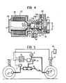
- the proportioning device actuator is indicated, of the type shown in Fig. 4, that operates the pressure modulation, controlled by micro-processor 7.
- control unit 5 and the proportioning device are preferably located in the engine compartment of the vehicle near the master cylinder 11.
- the micro-processor modulates pressure pp according to relation (4') stored in its memory, according to signals p A and pp that are fed continuously by sensors 3 and 4, and according to the values of a, b and Q inserted in its memory through sensors 1 and 2 before the vehicle starts.
- a device 16 activates sensors 1 and 2 when the vehicle is stationary or when at least one of the doors is open.
- Fig. 4 illustrates, by way of non-limiting example, a possible embodiment of the proportioning device with its actuator. It consists of a proportioning valve of a conventional type provided with an electromagnet for pressure modulation in response to the input signal received from the micro-processor.
- a plunger 20, having two portions having different diameters D and d is slidably mounted in a cylinder which has also two portions having different diameters, and is provided with a stationary sealing ring 27.
- a floating sealing ring 23 separates a high pressure chamber 21 from a low pressure chamber 25. The oil arrives at the chamber 21 through a hole 30 from the master cylinder at p " pressure, and from the chamber 25, through a hole 29, the oil goes out at pp pressure and it is sent to the rear brakes.
- An electromagnet 15 provides a thrust E against the plunger 20 by means of a winding 33, contained in a ferromagnetic material housing 32.
- the housing is closed by a cover 34.
- the device operates as follows.
- the oil at p A pressure which arrives into the chamber 21, passes through circumferential slots 24a and channel 24 b into the chamber 25 and therefrom it goes to the rear brakes.
- p " increase up to the value where the thrust on d diameter section is equivalent to the electromagnet E force
- the plunger moves toward the electromagnet until sealing ring 23 closes slots 24a.
- a p A increases furthermore, also the thrust on the annular section ⁇ /4(D 2 ⁇ d 2 ) increases and the plunger retracts slightly and opens again momentarily slots 24a. Consequently pressure pp increases again until the balance between p A , pp and E is attained and the plunger closes again slots 24a.
- pressure pp pushes ring 23 leftwards in the plunger groove and thus the oil from the rear circuit can flow back in the master cylinder, passing through the ring and the groove walls, and slots 22a cut in the rim 22 of the same plunger.
- the relationship between p " and pp is obtained by considering the equilibrium of the plunger under the different forces acting on it
- the proposed system can also be utilized, with small modifications, for further functions that in a normal brake system can be obtained only by adding some other rather expensive devices. For example, it can give a signal, through a suitable warning light, that one of the hydraulic circuits is defective.
- the Laws of some countries require these functions and these call for the addition in a normal braking system of a device which feels front and rear pressures and enters into action when only one of these pressures is zero, that is when one of the circuits has failed.
- the system of Fig. 3 can be simplified if a lower but satisfactory sensitivity to vehicle load variation is accepted.
- front wheel load sensor 1 is missing and there is only rear sensor 2.
- pressure pp sensor can be eliminated and the pressure modulation can be obtained by varying the electromagnet excitation without the feedback given by pressure pp sensor 4 of diagram Figs. 3 and 5.
- load sensor 1 and 2 can consist of sensors of the position of the wheels relative to vehicle body. This invention permits to greatly improve the wheels position sensors, if they are used.
- proportioning device actuator can obviously be a means different from an electromagnet, for example it could be an electric step-by-step engine or any other equivalent device.
- the fuel weight variations are not so important as to create dangerous errors.
- the errors can be completely eliminated by programming the micro-processor in such a way that it senses also the signal of the fuel level gauge in the tank, stores this signal with stationary vehicle, together with the load sensors signals and then, during the trip, calculates the weight variations on the basis of the fuel level variations.
- the fuel level gauge must be continually connected with the micro-processor during the trip.
Landscapes
- Engineering & Computer Science (AREA)
- Transportation (AREA)
- Mechanical Engineering (AREA)
- Regulating Braking Force (AREA)
- Hydraulic Control Valves For Brake Systems (AREA)
Claims (6)
Applications Claiming Priority (2)
| Application Number | Priority Date | Filing Date | Title |
|---|---|---|---|
| IT6746681 | 1981-04-03 | ||
| IT67466/81A IT1143485B (it) | 1981-04-03 | 1981-04-03 | Impianto frenante per autoveicoli con ripartitore di frenata controllato mediante elaboratore elettronico |
Publications (2)
| Publication Number | Publication Date |
|---|---|
| EP0062246A1 EP0062246A1 (fr) | 1982-10-13 |
| EP0062246B1 true EP0062246B1 (fr) | 1985-10-09 |
Family
ID=11302628
Family Applications (1)
| Application Number | Title | Priority Date | Filing Date |
|---|---|---|---|
| EP82102492A Expired EP0062246B1 (fr) | 1981-04-03 | 1982-03-25 | Système de freinage pour véhicules à moteur |
Country Status (3)
| Country | Link |
|---|---|
| EP (1) | EP0062246B1 (fr) |
| DE (1) | DE3266755D1 (fr) |
| IT (1) | IT1143485B (fr) |
Families Citing this family (28)
| Publication number | Priority date | Publication date | Assignee | Title |
|---|---|---|---|---|
| DE3302642C2 (de) * | 1983-01-27 | 1986-09-04 | Daimler-Benz Ag, 7000 Stuttgart | Antiblockiersystem für ein Zweirad-Straßenfahrzeug mit hydraulischer Zweikreis-Bremsanlage |
| DE3306611A1 (de) * | 1983-02-25 | 1984-08-30 | Alfred Teves Gmbh, 6000 Frankfurt | Verfahren und vorrichtung zur steuerung der bremskraftverteilung |
| DE3403236A1 (de) * | 1983-04-07 | 1985-08-01 | Alfred Teves Gmbh, 6000 Frankfurt | Bremsanlage fuer kraftfahrzeuge |
| DE3436223A1 (de) * | 1983-04-07 | 1986-04-03 | Alfred Teves Gmbh, 6000 Frankfurt | Bremsanlage fuer kraftfahrzeuge |
| DE3323402A1 (de) * | 1983-04-07 | 1984-10-18 | Alfred Teves Gmbh, 6000 Frankfurt | Bremsanlage fuer kraftfahrzeuge |
| DE3403237A1 (de) * | 1983-04-07 | 1985-08-01 | Alfred Teves Gmbh, 6000 Frankfurt | Bremsanlage fuer kraftfahrzeuge |
| DE3318020A1 (de) * | 1983-05-18 | 1984-11-22 | Robert Bosch Gmbh, 7000 Stuttgart | Zweikreisbremsanlage fuer fahrzeuge |
| DE3345694C2 (de) * | 1983-12-17 | 1996-04-04 | Teves Gmbh Alfred | Hydraulische Bremsanlage |
| DE3411743C2 (de) * | 1984-03-30 | 1994-05-26 | Teves Gmbh Alfred | Kraftfahrzeug-Bremsanlage mit elektronisch gesteuerter Vorderachs-/Hinterachs-Bremskraftverteilung |
| JPS6137569A (ja) * | 1984-07-31 | 1986-02-22 | Nissan Motor Co Ltd | ブレ−キ液圧制御装置 |
| JPS6137568A (ja) * | 1984-07-31 | 1986-02-22 | Nissan Motor Co Ltd | ブレ−キ液圧制御装置 |
| DE3434512A1 (de) * | 1984-09-20 | 1986-03-27 | Ingo 4500 Osnabrück Remmert | Elektrische steuereinrichtung fuer eine elektromagnetische bremse eines fahrzeuganhaengers |
| DE3502049A1 (de) * | 1985-01-23 | 1986-07-24 | Wabco Westinghouse Fahrzeugbremsen GmbH, 3000 Hannover | Bremsdrucksteuereinrichtung |
| US4603921A (en) * | 1985-06-06 | 1986-08-05 | Rockwell International Corporation | Brake proportioning system |
| GB8612066D0 (en) * | 1986-05-17 | 1986-06-25 | Lucas Ind Plc | Vehicle braking system |
| US4822113A (en) * | 1987-08-13 | 1989-04-18 | The Boeing Company | Braking torque control system |
| DE3840112C1 (fr) * | 1988-11-28 | 1990-01-25 | Edelhoff Polytechnik Gmbh & Co, 5860 Iserlohn, De | |
| DE3841749A1 (de) * | 1988-12-12 | 1990-06-13 | Wabco Westinghouse Fahrzeug | Verfahren und anordnung eines elektrisch gesteuerten bremskreises einer mehrkreis-bremsanlage mit druckmittelbetaetigten bremsen |
| JP3025009B2 (ja) * | 1989-07-19 | 2000-03-27 | ルーカス・インダストリーズ・パブリック・リミテッド・カンパニー | 2車軸乗物用ブレーキ装置 |
| DE3936726A1 (de) * | 1989-11-04 | 1991-05-08 | Wabco Westinghouse Fahrzeug | Verfahren zur abbremsung eines mit druckbetaetigten bremsen ausgeruesteten fahrzeugzuges |
| US5217284A (en) * | 1990-05-21 | 1993-06-08 | Robert Bosch Gmbh | Hydraulic dual-circuit brake system with dual pressure sensors and an active fluid reservoir |
| DE4016308A1 (de) * | 1990-05-21 | 1991-11-28 | Bosch Gmbh Robert | Hydraulische zweikreisbremsanlage |
| DE4022671A1 (de) * | 1990-07-17 | 1992-01-23 | Wabco Westinghouse Fahrzeug | Elektronisches bremssystem fuer stassenfahrzeuge |
| DE4026627A1 (de) * | 1990-08-23 | 1992-02-27 | Bosch Gmbh Robert | Fahrzeug |
| DE4124496A1 (de) * | 1991-07-24 | 1993-01-28 | Teves Gmbh Alfred | Bremsanlage fuer kraftfahrzeuge mit elektrischem antrieb |
| DE4126219A1 (de) * | 1991-08-08 | 1993-02-11 | Duerrwaechter E Dr Doduco | Verfahren zum herstellen von kontaktplaettchen |
| US5632535A (en) * | 1995-08-28 | 1997-05-27 | Kelsey-Hayes Company | Dynamic rear proportioning brake system |
| US7809486B2 (en) | 2005-04-29 | 2010-10-05 | Kelsey-Hayes Company | Pressure boost for vehicle rear brake circuits |
Family Cites Families (7)
| Publication number | Priority date | Publication date | Assignee | Title |
|---|---|---|---|---|
| GB1251832A (fr) * | 1968-01-15 | 1971-11-03 | ||
| DE2057973C2 (de) * | 1970-11-25 | 1984-07-05 | Robert Bosch Gmbh, 7000 Stuttgart | Bremskraftregelanlage |
| DE2622746A1 (de) * | 1976-05-21 | 1977-11-24 | Wabco Westinghouse Gmbh | Einrichtung zur bremskraftregelung von kraftfahrzeugen |
| DE2722435C3 (de) * | 1977-05-18 | 1984-02-23 | Wabco Westinghouse Fahrzeugbremsen GmbH, 3000 Hannover | Sicherheitsschaltung bei blockiergeschützten und lastabhängigen Fahrzeugbremsanlagen |
| DE2840262C3 (de) * | 1978-09-15 | 1995-04-20 | Knorr Bremse Ag | Einrichtung zur Steuerung pneumatischer oder elektro-pneumatischer Bremsen von Schienenfahrzeugen |
| JPS5599444A (en) * | 1979-01-23 | 1980-07-29 | Nissan Motor Co Ltd | Hydraulic brake controller |
| GB2049080B (en) * | 1979-05-10 | 1983-03-30 | Lucas Industries Ltd | Vehicle braking systems |
-
1981
- 1981-04-03 IT IT67466/81A patent/IT1143485B/it active
-
1982
- 1982-03-25 EP EP82102492A patent/EP0062246B1/fr not_active Expired
- 1982-03-25 DE DE8282102492T patent/DE3266755D1/de not_active Expired
Also Published As
| Publication number | Publication date |
|---|---|
| IT1143485B (it) | 1986-10-22 |
| EP0062246A1 (fr) | 1982-10-13 |
| DE3266755D1 (en) | 1985-11-14 |
| IT8167466A0 (it) | 1981-04-03 |
Similar Documents
| Publication | Publication Date | Title |
|---|---|---|
| EP0062246B1 (fr) | Système de freinage pour véhicules à moteur | |
| EP0961722B1 (fr) | Commande de frein pour remorque | |
| US5333940A (en) | Tractor/trailer brake pressure regulation method and system | |
| US4708225A (en) | Overload protection and/or warning arrangement | |
| EP0205277B1 (fr) | Système de freinage de véhicule | |
| US5615931A (en) | Method and apparatus for regulating the brake system of a vehicle | |
| US4093316A (en) | Combined antiskid and load-dependent brake control system for a motor vehicle | |
| US6655754B2 (en) | Vehicle brake system having adaptive torque control | |
| US4795219A (en) | Vehicle braking system | |
| US4824186A (en) | Hydraulic dual-circuit brake system | |
| US3802745A (en) | Brake installation especially for motor vehicles | |
| EP0617679B1 (fr) | Systeme de distribution du freinage destine a un vehicule a plusieurs essieux, utilisant des sources de freinage secondaires | |
| US4848852A (en) | Braking system for automotive vehicle | |
| US6089677A (en) | Braking force control apparatus | |
| US4677557A (en) | Multiple-axle vehicular braking effort distribution method and system | |
| EP0292687B1 (fr) | Système de commande pour un train routier | |
| US3825308A (en) | Proportioning valve control means | |
| US6099085A (en) | Method and apparatus for a deceleration-regulated braking system | |
| AU601346B2 (en) | Tractor-trailer brake control system | |
| ITMI952109A1 (it) | Procedimento e dispositivo per comandare rispettivamente regolare elettricamente l'impianto frenante di un veicolo | |
| EP0429066B1 (fr) | Système de freinage | |
| AU619474B2 (en) | Trailer mounted tractor-trailer brake control system | |
| US3761140A (en) | Hydraulically actuated adaptive braking system using a single fluid | |
| US4824185A (en) | Hydraulic dual-circuit braking system | |
| CA1320916C (fr) | Systeme de freins anti-blocage pour vehicule a essieux en tandem |
Legal Events
| Date | Code | Title | Description |
|---|---|---|---|
| PUAI | Public reference made under article 153(3) epc to a published international application that has entered the european phase |
Free format text: ORIGINAL CODE: 0009012 |
|
| AK | Designated contracting states |
Designated state(s): DE FR GB SE |
|
| 17P | Request for examination filed |
Effective date: 19821123 |
|
| GRAA | (expected) grant |
Free format text: ORIGINAL CODE: 0009210 |
|
| AK | Designated contracting states |
Designated state(s): DE FR GB SE |
|
| PG25 | Lapsed in a contracting state [announced via postgrant information from national office to epo] |
Ref country code: FR Free format text: THE PATENT HAS BEEN ANNULLED BY A DECISION OF A NATIONAL AUTHORITY Effective date: 19851009 |
|
| PG25 | Lapsed in a contracting state [announced via postgrant information from national office to epo] |
Ref country code: SE Effective date: 19851030 |
|
| REF | Corresponds to: |
Ref document number: 3266755 Country of ref document: DE Date of ref document: 19851114 |
|
| EN | Fr: translation not filed | ||
| PLBE | No opposition filed within time limit |
Free format text: ORIGINAL CODE: 0009261 |
|
| STAA | Information on the status of an ep patent application or granted ep patent |
Free format text: STATUS: NO OPPOSITION FILED WITHIN TIME LIMIT |
|
| 26N | No opposition filed | ||
| PG25 | Lapsed in a contracting state [announced via postgrant information from national office to epo] |
Ref country code: GB Free format text: LAPSE BECAUSE OF NON-PAYMENT OF DUE FEES Effective date: 19881121 |
|
| GBPC | Gb: european patent ceased through non-payment of renewal fee | ||
| PG25 | Lapsed in a contracting state [announced via postgrant information from national office to epo] |
Ref country code: DE Effective date: 19881201 |
|
| R20 | Corrections of a patent specification |
Effective date: 19891221 |