EP0062130A1 - Wheel trim - Google Patents
Wheel trim Download PDFInfo
- Publication number
- EP0062130A1 EP0062130A1 EP81305975A EP81305975A EP0062130A1 EP 0062130 A1 EP0062130 A1 EP 0062130A1 EP 81305975 A EP81305975 A EP 81305975A EP 81305975 A EP81305975 A EP 81305975A EP 0062130 A1 EP0062130 A1 EP 0062130A1
- Authority
- EP
- European Patent Office
- Prior art keywords
- wheel
- strip
- trim
- adhesive
- rim
- Prior art date
- Legal status (The legal status is an assumption and is not a legal conclusion. Google has not performed a legal analysis and makes no representation as to the accuracy of the status listed.)
- Withdrawn
Links
Images
Classifications
-
- B—PERFORMING OPERATIONS; TRANSPORTING
- B60—VEHICLES IN GENERAL
- B60B—VEHICLE WHEELS; CASTORS; AXLES FOR WHEELS OR CASTORS; INCREASING WHEEL ADHESION
- B60B7/00—Wheel cover discs, rings, or the like, for ornamenting, protecting, venting, or obscuring, wholly or in part, the wheel body, rim, hub, or tyre sidewall, e.g. wheel cover discs, wheel cover discs with cooling fins
- B60B7/01—Rings specially adapted for covering only the wheel rim or the tyre sidewall, e.g. removable tyre sidewall trim rings
Definitions
- This invention relates to wheel trims for embellishing the road wheels of vehicles such as cars.
- Custom-made wheel trims are a problem for all concerned.
- the manufacturer has to produce a wheel trim for each size of wheel. Because each packaged wheel trim set will take up a lot of space, the manufacturer must have a large storage area to accommodate a full range of sizes, and much space is involved in transportation. The retailer also suffers from the problem of storage of a full range of sizes.
- wheels which have been cast, for example of an aluminium-magnesium alloy.
- Such wheels are very expensive and, although they are usually highly polished to start with, they soon become tarnished and encrusted with corrosion.
- the wheel trim serves to mount the tyre trim and is secured to the lip of the wheel rim by means of a plurality of clips.
- An object of the invention is to provide a wheel trim which can be fitted to any size of vehicle wheel, so as to embellish the wheel, and which can be fitted in a very simple and convenient manner by the vehicle owner, without the use of special tools or skill.
- the present invention provides a wheel trim comprising a strip of substantially L-shaped cross-section and joining means joining free ends of the strip together to form an annulus characterised in that the upright of the L is shaped so as to directly interfit with the rim of a vehicle wheel, within a circular space defined by the rim, to embellish the wheel.
- the strip is preferably a metal foil coated in a plastics material.
- the joining means may conveniently be a clip of substantially L-shaped cross-section, and this clip may have lips on the free ends of the upright and foot of the L for engaging around the strip. Then, the clip may be crimped onto the free ends of the strip.
- adhesive may be provided on the upright of the L-shaped strip.
- This adhesive may be, for instance, in the form of adhesive blobs or a self-adhesive band, e.g. of extruded foam, about a quarter of an inch wide, Such a band may have a protective wrapping covering the adhesive, this wrapping being removed before the wheel trim is fitted to its wheel, when the self-adhesive band will serve to hold the trim in place.
- the strip may have formations, preferably resilient, which serve to resist removal of the trim from the wheel or reduce slack between the trim and the wheel.
- the wheel trim of the invention may be sold as a kit comprising a strip and joining means in the form of a clip.
- the invention also provides, as a further feature thereof, a method of making a wheel trim comprising a strip of substantially L-shaped cross-section and joining means, which comprises joining free ends of the strip together by the joining means to form an annulus which will interfit the rim of a vehicle wheel to embellish the wheel.
- the preferred embodiment of the wheel trim of the invention illustrated in Figs. 1 to 3 comprises a strip 10 of substantially L-shaped cross-section and, as joining means, a clip 15.
- the strip 10 has a broad portion 11 corresponding to the upright of the L and a foot portion 12 corresponding to the foot of the L.
- the strip 10 comprises a metal foil 13 ooated with a plastics material 14, e.g. by extrusion.
- the clip 15 is made of aluminium or like metal or alloy, which may be crimped, and comprises a substantially L-shaped body 16 having lips 18 at the free ends of the upright and foot of the L. Defined between the lips 18 and the clip body 16 are grooves 19 which can accept the free ends of the strip 10. The arrangement of the lips 18 is readily discernable from Fig. 1.
- annulus 20 When the free ends of the strip 10 are located in the clip 15 they form an annulus 20, as illustrated in Fig. 2.
- the annulus 20 may be fitted into a wheel 21, as illustrated in Fig. 3, the wheel comprising a body 22 having a rim 23 and a tyre 24.
- the wheel trim is assembled in the following manner.
- the free ends of the strip 10 are joined together by being pushed into the clip 15 and are retained by the lips 18 of the clip 15, with the foot portion 12 of the strip 10 projecting outwardly from the axis of the annulus 20 formed by the strip 10 and the clip 15.
- the annulus 20 is now offered up to the wheel it is required to fit. If the annulus 20 is too large to fit inside the wheel rim 23, one end of the strip 10 can be taken out of the clip 15 and a short length cut off the strip 10.
- the step, of offering up the annulus-20 to the wheel 21 and then cutting off some of the strip are repeated until the annulus 20 will fit tightly into the wheel rim 23.
- the clip 15 is crimped tightly onto the free ends of the strip 10, making the wheel trim a permanent annulus 20.
- the wheel trim is then pushed home inside the wheel rim 23 as illustrated in Fig. 3 where it embellishes the wheel 21.
- the strip 10 should be cut to exactly the right size as discussed above, otherwise adjustments (e.g. the introduction of a spacer between the facing ends of the strip, 10 within the clip 15) may be necessary.
- the accuracy needed for fitting the strip 10 can be reduced somewhat by use of a modified strip configuration, such as is illustrated in Fig. 4 or by providing for the strip to be adhered in place, as is illustrated in-Fig. 5.
- the broad portion 11 of the strip 10 has formations which serve to engage with the wheel rim 23 and resist separation or removal of the trim. These formations are in the form of integrally-moulded saw-tooth shaped ribs or protrusions 25 which extend all the way around the annulus formed by the strip 10. These ribs or protrusions 25 will yield at least to a small extent when the trim is fitted to the wheel.
- a modification of the embodiment shown in Fig. 4 may have protrusions 25 which are larger and more resilient than those shown in Fig. 4 and which serve to reduce slack between the wheel trim and the wheel.
- adhesive in the form of blobs 26 is provided to secure the wheel trim in place.
- the blobs 26 may be applied either to the wheel rim or, more preferably, to the broad portion 11 of the strip 10.
- the blobs 26 act not only as adhesive, but also as a partially deformable packing material between the trim and the rim 23.
- the strip 10 has, along the majority of the broad portion 11 of its length, a self-adhesive band of extruded plastics foam.
- This self-adhesive band which is about a quarter of an inch wide, has adhesive on two opposing surfaces.
- the adhesive can be applied to the self-adhesive as a continuous film or discrete blobs or by a doctor blade technique.
- the adhesive on one side of the self-adhesive band secures the self-adhesive band to the strip 10.
- the adhesive on the other side of the self-adhesive band is covered by a protective wrapping which is removed before fitting the trim to its wheel.
- the wheel trim of the invention is not limited to the above described embodiments.
- the strip can be all metal or all plastics, and, if it is wholly plastics, the joining means can be an adhesive.
- a wheel trim of the present invention over conventional wheel trims are innumerable. It is, easy to fit to any size of vehicle wheel; the only tools needed are tools to cut the strip, such as a strong pair of scissors, and a tool for crimping the clip (if a clip provides the joining means). Because the wheel trim comes in only one size and only takes up a small amount of space, the costs of manufacture and distribution are kept low, thereby providing the wheel trim as an inexpensive accessory for the vehicle owner who wishes to embellish the wheels of his vehicle.
Abstract
Free ends of a strip (10) are inserted into a clip (15) to form an annulus (20) which is offered up to the wheel (not shown) it is required to fit. The size of the annulus (20) is adjusted, by cutting pieces off one end of the strip (10), until the annulus (20) will fit tightly into the wheel's rim. Then the clip (15) is crimped onto the free ends of permanent annulus (20).
Description
- This invention relates to wheel trims for embellishing the road wheels of vehicles such as cars.
- Car owners often like to improve the appearance of their cars and usually start by improving the look of the road wheels. At bresent not much can be done to improve the appearance of conventional wheels of pressed steel except to change their colour witn paint or to fit custom-made wheel trims. However, the appearance of a re-painted wheel quickly deteriorates as the paint becomes chipped and scratched.
- Custom-made wheel trims are a problem for all concerned. The manufacturer has to produce a wheel trim for each size of wheel. Because each packaged wheel trim set will take up a lot of space, the manufacturer must have a large storage area to accommodate a full range of sizes, and much space is involved in transportation. The retailer also suffers from the problem of storage of a full range of sizes.
- As an alternative to re-painting or fitting custom made wheel trims, one can fit wheels which have been cast, for example of an aluminium-magnesium alloy. Such wheels are very expensive and, although they are usually highly polished to start with, they soon become tarnished and encrusted with corrosion.
- It is also possible, as disclosed in British Patent Specification No. 848716, to fit a combined tyre trim-wheel trim to a vehicle wheel. In this case, the wheel trim serves to mount the tyre trim and is secured to the lip of the wheel rim by means of a plurality of clips.
- An object of the invention is to provide a wheel trim which can be fitted to any size of vehicle wheel, so as to embellish the wheel, and which can be fitted in a very simple and convenient manner by the vehicle owner, without the use of special tools or skill.
- Pursuant hereto, the present invention provides a wheel trim comprising a strip of substantially L-shaped cross-section and joining means joining free ends of the strip together to form an annulus characterised in that the upright of the L is shaped so as to directly interfit with the rim of a vehicle wheel, within a circular space defined by the rim, to embellish the wheel.
- The strip is preferably a metal foil coated in a plastics material. The joining means may conveniently be a clip of substantially L-shaped cross-section, and this clip may have lips on the free ends of the upright and foot of the L for engaging around the strip. Then, the clip may be crimped onto the free ends of the strip.
- For contributing to the security of fitting of the wheel trim to a wheel rim adhesive may be provided on the upright of the L-shaped strip. This adhesive may be, for instance, in the form of adhesive blobs or a self-adhesive band, e.g. of extruded foam, about a quarter of an inch wide, Such a band may have a protective wrapping covering the adhesive, this wrapping being removed before the wheel trim is fitted to its wheel, when the self-adhesive band will serve to hold the trim in place.
- Alternatively, or in addition to the adhesive, the strip may have formations, preferably resilient, which serve to resist removal of the trim from the wheel or reduce slack between the trim and the wheel.
- The wheel trim of the invention may be sold as a kit comprising a strip and joining means in the form of a clip.
- The invention also provides, as a further feature thereof, a method of making a wheel trim comprising a strip of substantially L-shaped cross-section and joining means, which comprises joining free ends of the strip together by the joining means to form an annulus which will interfit the rim of a vehicle wheel to embellish the wheel.
- The invention will be described further, by way of example, with reference to the accompanying drawing in which:-
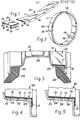
- Fig. 1 is a perspective view illustrating the components of a preferred embodiment of the wheel trim of the invention;
- Fig. 2 is a perspective view illustrating the components of Fig. 1 assembled to form the wheel trim, to a reduced scale compared with Fig. 1;
- Fig. 3 is an enlarged radial section through part of a wheel illustrating the wheel trim of Fig. 2 fitted in place;
- Fig. 4 is a section comparable with part of Fig. 3, but to a further enlarged scale, and illustrating a second embodiment of the wheel trim of the invention; and
- Fig. 5 is a view similar to Fig. 4 illustrating a third embodiment.
- The preferred embodiment of the wheel trim of the invention illustrated in Figs. 1 to 3 comprises a
strip 10 of substantially L-shaped cross-section and, as joining means, aclip 15. Thestrip 10 has abroad portion 11 corresponding to the upright of the L and afoot portion 12 corresponding to the foot of the L. Thestrip 10 comprises ametal foil 13 ooated with aplastics material 14, e.g. by extrusion. - The
clip 15 is made of aluminium or like metal or alloy, which may be crimped, and comprises a substantially L-shaped body 16 havinglips 18 at the free ends of the upright and foot of the L. Defined between thelips 18 and theclip body 16 aregrooves 19 which can accept the free ends of thestrip 10. The arrangement of thelips 18 is readily discernable from Fig. 1. - When the free ends of the
strip 10 are located in theclip 15 they form anannulus 20, as illustrated in Fig. 2. Theannulus 20 may be fitted into awheel 21, as illustrated in Fig. 3, the wheel comprising abody 22 having arim 23 and atyre 24. - The wheel trim is assembled in the following manner. The free ends of the
strip 10 are joined together by being pushed into theclip 15 and are retained by thelips 18 of theclip 15, with thefoot portion 12 of thestrip 10 projecting outwardly from the axis of theannulus 20 formed by thestrip 10 and theclip 15. Theannulus 20 is now offered up to the wheel it is required to fit. If theannulus 20 is too large to fit inside thewheel rim 23, one end of thestrip 10 can be taken out of theclip 15 and a short length cut off thestrip 10. The step, of offering up the annulus-20 to thewheel 21 and then cutting off some of the strip are repeated until theannulus 20 will fit tightly into thewheel rim 23. When the correct fit has been achieved, theclip 15 is crimped tightly onto the free ends of thestrip 10, making the wheel trim apermanent annulus 20. The wheel trim is then pushed home inside thewheel rim 23 as illustrated in Fig. 3 where it embellishes thewheel 21. - To achieve an effective fit of the wheel trim, with the
wheel rim 23, thestrip 10 should be cut to exactly the right size as discussed above, otherwise adjustments (e.g. the introduction of a spacer between the facing ends of the strip, 10 within the clip 15) may be necessary. The accuracy needed for fitting thestrip 10 can be reduced somewhat by use of a modified strip configuration, such as is illustrated in Fig. 4 or by providing for the strip to be adhered in place, as is illustrated in-Fig. 5. - In the embodiment of Fig. 4 the
broad portion 11 of thestrip 10 has formations which serve to engage with thewheel rim 23 and resist separation or removal of the trim. These formations are in the form of integrally-moulded saw-tooth shaped ribs orprotrusions 25 which extend all the way around the annulus formed by thestrip 10. These ribs orprotrusions 25 will yield at least to a small extent when the trim is fitted to the wheel. - A modification of the embodiment shown in Fig. 4 may have
protrusions 25 which are larger and more resilient than those shown in Fig. 4 and which serve to reduce slack between the wheel trim and the wheel. - In the embodiment of Fig. 5 adhesive, in the form of
blobs 26 is provided to secure the wheel trim in place. Theblobs 26 may be applied either to the wheel rim or, more preferably, to thebroad portion 11 of thestrip 10. Theblobs 26 act not only as adhesive, but also as a partially deformable packing material between the trim and therim 23. - In another embodiment (not shown), the
strip 10 has, along the majority of thebroad portion 11 of its length, a self-adhesive band of extruded plastics foam. This self-adhesive band, which is about a quarter of an inch wide, has adhesive on two opposing surfaces. The adhesive can be applied to the self-adhesive as a continuous film or discrete blobs or by a doctor blade technique. The adhesive on one side of the self-adhesive band secures the self-adhesive band to thestrip 10. The adhesive on the other side of the self-adhesive band is covered by a protective wrapping which is removed before fitting the trim to its wheel. - The wheel trim of the invention is not limited to the above described embodiments. The strip can be all metal or all plastics, and, if it is wholly plastics, the joining means can be an adhesive.
- The advantages of a wheel trim of the present invention over conventional wheel trims are innumerable. It is, easy to fit to any size of vehicle wheel; the only tools needed are tools to cut the strip, such as a strong pair of scissors, and a tool for crimping the clip (if a clip provides the joining means). Because the wheel trim comes in only one size and only takes up a small amount of space, the costs of manufacture and distribution are kept low, thereby providing the wheel trim as an inexpensive accessory for the vehicle owner who wishes to embellish the wheels of his vehicle.
Claims (15)
1. A wheel trim comprising a strip of substantially L-shaped cross-section and joining means joining free ends of the strip together to form an annulus characterised in that the upright of the L is shaped as to so/directly interfit with the rim of a vehicle wheel, within a circular space defined by the rim, to embellish the wheel.
2. A wheel trim as claimed in claim 1, further. characterised in that the strip is a metal foil coated with a plastics material.
3. A wheel trim as claimed in claim 1 or 2, further characterised in that the joining means is a clip.
4. A wheel trim as claimed in claim 3, further characterised in that the clip is substantially L-shaped in cross-section having lips at the free ends of the upright and foot of the L for engaging around the strip.
5. A wheel trim as claimed in any preceding claim characterised by provision of adhesive on the strip to adhere the trim to the wheel rim.
6. A wheel trim as claimed in claim 5 characterised in that adhesive is in the form of blobs.
7. A wheel trim as claimed in claim 5 further characterised by provision of the adhesive as a self-adhesive band having adhesive on two opposing sides, the adhesive on one side securing the self-adhesive band to the strip of the wheel trim and the adhesive on the other side serving to adhere the trim to the wheel rim.
8. A wheel trim as claimed in any of claims 1 to 6 characterised in that the strip has formations which serve to resist removal of the wheel trim from a wheel rim.
9. A wheel trim as claimed in any preceding claim further characterised in that the strip has formations which are resilient and serve to reduce slack the wheel between/trim and the rim.
10. A wheel trim substantially as hereinbefore described with reference to and as illustrated in the accompanying drawing.
11. A method of making a wheel trim comprising a strip of substantially L-shaped cross-section and joining means, which comprises joining free ends of the strip together by the joining means to form an annulus characterised in that said annulus is shaped to directly interfit the rim of the vehicle wheel, within a circular space defined by the rim, to embellish the wheel.
12. A method as claimed in claim 11 further characterised in that the joining means is a clip, and further including a step of crimping the clip onto the free ends of the strip.
13. A method as claimed in claim 11 or 12 characterised by provision of adhesive to retain the wheel trim the rim of a wheel.
14. A method of making a wheel trim substantially as hereinbefore described with reference to and as illustrated in the accompanying drawing.
15. A kit of parts comprising a strip of substantially L-shaped cross-section and joining means in the form of a clip, for producing a wheel trim as claimed in any of claims 1 to 10.
Applications Claiming Priority (2)
| Application Number | Priority Date | Filing Date | Title |
|---|---|---|---|
| GB8110846 | 1981-04-07 | ||
| GB8110846A GB2096068A (en) | 1981-04-07 | 1981-04-07 | Wheel trim |
Publications (1)
| Publication Number | Publication Date |
|---|---|
| EP0062130A1 true EP0062130A1 (en) | 1982-10-13 |
Family
ID=10520992
Family Applications (1)
| Application Number | Title | Priority Date | Filing Date |
|---|---|---|---|
| EP81305975A Withdrawn EP0062130A1 (en) | 1981-04-07 | 1981-12-21 | Wheel trim |
Country Status (2)
| Country | Link |
|---|---|
| EP (1) | EP0062130A1 (en) |
| GB (1) | GB2096068A (en) |
Cited By (6)
| Publication number | Priority date | Publication date | Assignee | Title |
|---|---|---|---|---|
| EP0177773A2 (en) * | 1984-09-13 | 1986-04-16 | International Technical Research S.A.H. | Securing of a balancing weight onto a vehicle wheel |
| WO1993007012A2 (en) * | 1991-10-11 | 1993-04-15 | Von Heyking Gmbh | Wheel rim and a protective element, in particular a ring, for a wheel rim |
| GB2319754A (en) * | 1996-11-30 | 1998-06-03 | Richard Young | Wheel trim and hub cap retention |
| WO2000024595A1 (en) * | 1998-10-27 | 2000-05-04 | Wheeltech, Besloten Vennootschap Met Beperkte Aans Prakelijkheid | Accessory for light metal wheel rims |
| US7452036B1 (en) | 2008-04-18 | 2008-11-18 | Diko Sulahian | Vehicle wheel assembly with transition ring member |
| US7537289B2 (en) | 2007-06-25 | 2009-05-26 | Sulahian Diko | Vehicle wheel assembly with transition ring member |
Families Citing this family (4)
| Publication number | Priority date | Publication date | Assignee | Title |
|---|---|---|---|---|
| US4978174A (en) * | 1989-09-29 | 1990-12-18 | Nosler John C | Low-weight, low-aerodynamic-drag disk wheel cover |
| AU642300B2 (en) * | 1991-09-18 | 1993-10-14 | Crimson Company Limited | An insert and/or ornament for automotive wheel |
| DE19608238A1 (en) * | 1996-03-04 | 1997-09-18 | Bayerische Motoren Werke Ag | Rim for vehicle wheel |
| GB2397561A (en) * | 2003-01-23 | 2004-07-28 | Ansar Mahmood | Vehicle wheel rim protector |
Citations (7)
| Publication number | Priority date | Publication date | Assignee | Title |
|---|---|---|---|---|
| US1855022A (en) * | 1931-08-10 | 1932-04-19 | Motor Products Corp | Annular finish strip and method of constructing the same |
| FR1242067A (en) * | 1959-02-06 | 1960-09-23 | Vehicle wheel cover trim | |
| US2963325A (en) * | 1958-03-06 | 1960-12-06 | Jr Charles B Aske | Vehicle wheel trim |
| FR1249390A (en) * | 1959-11-09 | 1960-12-30 | Extendable hubcap for vehicle wheels, and method of manufacturing | |
| DE1123932B (en) * | 1957-07-15 | 1962-02-15 | Charles Birger Aske | Tire trim ring |
| US3256044A (en) * | 1964-06-15 | 1966-06-14 | Illinois Tool Works | Wheel opening plug |
| US3891276A (en) * | 1973-08-02 | 1975-06-24 | S & S Product Engineering Serv | Wheel and wheel trim assembly |
-
1981
- 1981-04-07 GB GB8110846A patent/GB2096068A/en not_active Withdrawn
- 1981-12-21 EP EP81305975A patent/EP0062130A1/en not_active Withdrawn
Patent Citations (7)
| Publication number | Priority date | Publication date | Assignee | Title |
|---|---|---|---|---|
| US1855022A (en) * | 1931-08-10 | 1932-04-19 | Motor Products Corp | Annular finish strip and method of constructing the same |
| DE1123932B (en) * | 1957-07-15 | 1962-02-15 | Charles Birger Aske | Tire trim ring |
| US2963325A (en) * | 1958-03-06 | 1960-12-06 | Jr Charles B Aske | Vehicle wheel trim |
| FR1242067A (en) * | 1959-02-06 | 1960-09-23 | Vehicle wheel cover trim | |
| FR1249390A (en) * | 1959-11-09 | 1960-12-30 | Extendable hubcap for vehicle wheels, and method of manufacturing | |
| US3256044A (en) * | 1964-06-15 | 1966-06-14 | Illinois Tool Works | Wheel opening plug |
| US3891276A (en) * | 1973-08-02 | 1975-06-24 | S & S Product Engineering Serv | Wheel and wheel trim assembly |
Cited By (10)
| Publication number | Priority date | Publication date | Assignee | Title |
|---|---|---|---|---|
| EP0177773A2 (en) * | 1984-09-13 | 1986-04-16 | International Technical Research S.A.H. | Securing of a balancing weight onto a vehicle wheel |
| EP0177773A3 (en) * | 1984-09-13 | 1986-12-30 | International Technical Research S.A.H. | Securing of a balancing weight onto a vehicle wheel |
| US4720149A (en) * | 1984-09-13 | 1988-01-19 | International Technical Research S.A.H. | Mounting means for mounting balance weights on a motor vehicle wheel |
| WO1993007012A2 (en) * | 1991-10-11 | 1993-04-15 | Von Heyking Gmbh | Wheel rim and a protective element, in particular a ring, for a wheel rim |
| WO1993007012A3 (en) * | 1991-10-11 | 1993-05-27 | Heyking Gmbh | Wheel rim and a protective element, in particular a ring, for a wheel rim |
| GB2319754A (en) * | 1996-11-30 | 1998-06-03 | Richard Young | Wheel trim and hub cap retention |
| WO2000024595A1 (en) * | 1998-10-27 | 2000-05-04 | Wheeltech, Besloten Vennootschap Met Beperkte Aans Prakelijkheid | Accessory for light metal wheel rims |
| BE1012250A3 (en) * | 1998-10-27 | 2000-08-01 | Wheeltech Bvba | Attachment for light metal wheel rims. |
| US7537289B2 (en) | 2007-06-25 | 2009-05-26 | Sulahian Diko | Vehicle wheel assembly with transition ring member |
| US7452036B1 (en) | 2008-04-18 | 2008-11-18 | Diko Sulahian | Vehicle wheel assembly with transition ring member |
Also Published As
| Publication number | Publication date |
|---|---|
| GB2096068A (en) | 1982-10-13 |
Similar Documents
| Publication | Publication Date | Title |
|---|---|---|
| CA1275131A (en) | Splash guard | |
| EP0062130A1 (en) | Wheel trim | |
| USD335643S (en) | Automobile tire | |
| JP3307398B2 (en) | Automotive wheel with annular device | |
| USD368687S (en) | Automobile tire | |
| USD377635S (en) | Automobile tire | |
| USD374200S (en) | Automobile tire | |
| USD368245S (en) | Automobile tire | |
| USD286274S (en) | Tire for a vehicle wheel | |
| USD395857S (en) | Automobile tire | |
| USD388752S (en) | Automobile tire | |
| US5273345A (en) | Wheel weight channel conceal band | |
| JP3516265B2 (en) | Retrofit rim protector for automotive wheels | |
| USD268663S (en) | Tire for a vehicle wheel | |
| USD384604S (en) | Automobile tire | |
| USD371758S (en) | Automobile tire | |
| USD410419S (en) | Automobile tire | |
| USD410601S (en) | Automobile tire | |
| USD269865S (en) | Tire for a vehicle wheel | |
| USD409954S (en) | Automobile tire | |
| USD269174S (en) | Tire | |
| USD384917S (en) | Automobile tire | |
| USD418784S (en) | Automobile tire | |
| USD419924S (en) | Automobile tire | |
| USD284179S (en) | Tire for a vehicle wheel |
Legal Events
| Date | Code | Title | Description |
|---|---|---|---|
| PUAI | Public reference made under article 153(3) epc to a published international application that has entered the european phase |
Free format text: ORIGINAL CODE: 0009012 |
|
| AK | Designated contracting states |
Designated state(s): AT BE CH DE FR IT LU NL SE |
|
| STAA | Information on the status of an ep patent application or granted ep patent |
Free format text: STATUS: THE APPLICATION IS DEEMED TO BE WITHDRAWN |
|
| 18D | Application deemed to be withdrawn |
Effective date: 19831003 |