US1855022A - Annular finish strip and method of constructing the same - Google Patents
Annular finish strip and method of constructing the same Download PDFInfo
- Publication number
- US1855022A US1855022A US556262A US55626231A US1855022A US 1855022 A US1855022 A US 1855022A US 556262 A US556262 A US 556262A US 55626231 A US55626231 A US 55626231A US 1855022 A US1855022 A US 1855022A
- Authority
- US
- United States
- Prior art keywords
- split ring
- strip
- finish
- finish strip
- same
- Prior art date
- Legal status (The legal status is an assumption and is not a legal conclusion. Google has not performed a legal analysis and makes no representation as to the accuracy of the status listed.)
- Expired - Lifetime
Links
- 238000000034 method Methods 0.000 title description 5
- 230000008878 coupling Effects 0.000 description 13
- 238000010168 coupling process Methods 0.000 description 13
- 238000005859 coupling reaction Methods 0.000 description 13
- 239000011324 bead Substances 0.000 description 2
- 238000004519 manufacturing process Methods 0.000 description 2
- 241001076939 Artines Species 0.000 description 1
- 241000905957 Channa melasoma Species 0.000 description 1
- 102000010029 Homer Scaffolding Proteins Human genes 0.000 description 1
- 108010077223 Homer Scaffolding Proteins Proteins 0.000 description 1
- 238000010276 construction Methods 0.000 description 1
- 239000000463 material Substances 0.000 description 1
- 238000012986 modification Methods 0.000 description 1
- 230000004048 modification Effects 0.000 description 1
Images
Classifications
-
- B—PERFORMING OPERATIONS; TRANSPORTING
- B60—VEHICLES IN GENERAL
- B60B—VEHICLE WHEELS; CASTORS; AXLES FOR WHEELS OR CASTORS; INCREASING WHEEL ADHESION
- B60B7/00—Wheel cover discs, rings, or the like, for ornamenting, protecting, venting, or obscuring, wholly or in part, the wheel body, rim, hub, or tyre sidewall, e.g. wheel cover discs, wheel cover discs with cooling fins
- B60B7/01—Rings specially adapted for covering only the wheel rim or the tyre sidewall, e.g. removable tyre sidewall trim rings
-
- Y—GENERAL TAGGING OF NEW TECHNOLOGICAL DEVELOPMENTS; GENERAL TAGGING OF CROSS-SECTIONAL TECHNOLOGIES SPANNING OVER SEVERAL SECTIONS OF THE IPC; TECHNICAL SUBJECTS COVERED BY FORMER USPC CROSS-REFERENCE ART COLLECTIONS [XRACs] AND DIGESTS
- Y10—TECHNICAL SUBJECTS COVERED BY FORMER USPC
- Y10T—TECHNICAL SUBJECTS COVERED BY FORMER US CLASSIFICATION
- Y10T29/00—Metal working
- Y10T29/49—Method of mechanical manufacture
- Y10T29/49481—Wheel making
- Y10T29/49492—Land wheel
- Y10T29/4954—Wheel trim making, e.g., wheel cover, hubcap
Definitions
- the present vogue in. motor vehicles demands the application to the wheel rims, hubs and the like, of a finish or trim strip or rail usually of a contrasting color for the purpose of im artin an ornamentalappearance thereto an to en ance generally the appearance of the wheel, hub or the like.
- this finish strip in the form of a complete annulus and to thereafter secure the same to the rim, hub or the like, either by means of anchorage means attached to the shpporting surface or by means of beads, grooves or the like formed therein.
- the invention contemplates forming the finish strip in the form of a split ring member of slightly greater length than the required finished size, whereupon the finish strip may be placed against the wheel rim or other supporting surface and the correct length or diameter accurately gauged, whereupon the split ring member may be severed to length.
- the invention also contemplates a coupling member readily engageable with the ends of the split ring member whereby the ends may be connected to form a complete annulus which thereafter may be secured to the supporting surface such as the wheel rim in the customary manner.
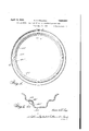
- Figure 1 is a side elevational view of a vehicle wheel rim or the like, having attached thereto a finished strip or'trim rail constructed in accordance with my invention
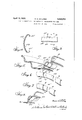
- Figure 2 is a transverse sectional view takep substantially on the line 2-2 in Fig- Figure 3 is an enlarged fragmentary elevational view of the connected ends to the split ring member;
- Figure 4 is a sectional view taken substantially on the line indicated as 44 in Fig ure 3;
- Figure 5 is a fragmentary cross sectional perspective view throu h a vehicle rim showing the manner in whlch the finish strip is ggugled to obtain the correct diameter of the 'is ed annulus;
- Figure 6 is a perspective view of the ends of the split ring member showing the coupling element ready to be attached to the ends of the split ring;
- Figure 7 is a view somewhat similar to Figure 6 showing the coupling member associated with one end of the split ring and just pridor to the joining of the two split ring ends, an
- Figure 8 isa fragmentary cross sectional perspective view through a wheel rim showing the end of a split ring finish strip of slightly different form.
- a vehicle wheel rim 10 of the drop-center type to which it is the present custom to attach in any one of a various number of ways a finish strip or trim rail 11.
- the'trim strip 11 is shown as secured to the rim by engaging the inner periphery thereof with the wall portion 10'of the rim and engaging the-outer pefirifihery with beads 12 formed. -circumferen y of the run.
- finish strip 11 may be secured to its supporting surface in any other pre ferred or desired manner, insofar as this invention is concerned, as will become more apparent as this description proceeds.
- the finish strip or trim rail in the form of a split ring which will be furnished to the wheel rim manufacturer or automobile manufacturer in diameters or lengths slightly in excess of the desired fin-. ished diameter of the complete annular finish strip.
- the finish strip may be matched with the wheel rim by placing the same in position and permitting the ends A and B thereof to overlap. In this manner the proper diameter for the finished annulus may be readily determined and may be marked as, for instance,
- the split 'ring can be removed from the rim and the excess material between the line B and the adjacent end severed in any preferred or desired manner. At this time there is produced a split ring of the desired diameter for the complete annulus and of a size which will accurately fit the rim against which the-split ring has been matched or i measured.
- the finish strip or trim rail is of a substantial channel shape in cross section and as a consequence comprises return-bent edges 11, the channel, when the finish strip is applied, facing inwardly against the opposed surface of the wheel rim.
- the coupling member in this form of the invention will engage the opposite ends of the split ring member tightly so as to be secured theretoby friction and the abutting ends of the split ring member match one another sufliciently and abut so closely that the joint formed by the abutting ends is but slightly noticeable, particularly when the finish strip is applied to its supporting surface.
- finish strips or trim rails having other cross sectional contours are capable of use in connection with this invention.
- the finish strip 14 instead of being outwardly bowed as in the other figures of the drawings, is bowed inwardly.
- the finish strips need not necessarily be channeled in cross section, other means thereupon being provided for connecting the coupling element to the ends of the split ring member.
- a ring-like finish strip comprising, a split ring member, and a coupling member enga ing the opposed ends of said split ring mem er to connect the same.
- An annular finish strip or trim rail comprising, a split ring member, and a separate coupling member engageable with the opposed ends of said split ring member to connect the same to form a complete annulus.
- a ring-like finish strip or trim rail adapted for attachment to a vehicle wheel rim comprising, a split ring member, and a cou-' tions of the opposed ends of said ring member to connect the same to form a complete annulus.
- An ornamental finish ring for a vehicle rim comprising, a split ring member of substantial channel cross section at the ends thereof, and a coupling member engaging the said channel portions of the opposed ends of said ring member to connect the same, the saidcquplmg member being concealed from view when the said ends are connected and the finish ring applied to the vehicle rim, the said finish ring being capable of attachment to the vehicle rim as a complete annulus.
Landscapes
- Engineering & Computer Science (AREA)
- Mechanical Engineering (AREA)
- Steering Controls (AREA)
Description
April 19, 1932. H. G. KELLOGG 1,855,022
ANNULAR FINISH STRIP AND METHOD OF CONSTRUCTING THE SAME Filed Aug. 10, 1931 2 Sheets-Sheet l INVENTfI wmmwmd Madam;
ATTORNE April 19, 1932.
H. G. KELLOGG .ANNULAR FINISH STRIP AND METHOD OF CONSTRUCTING THE SAME Filed Aug. 10, 1931 2 Sheets-Sheet 2 0mm 1mm Tam;
ATTO RN EY Patented Apr. 19, 1932 UNITED STATES,
PATENT OFFICE 30m G. KELIIbOGG, OFDETBOIT, MICHIGAN, ABSIGNOB IO IOZIL'OB IBODUULB COB- POB-ATION, O1 DETROIT, MICHIGAN, A CORPORATION 01 YORK m rnnsn STRIP AND IETHOD O1 OONS'JEBUCTDTG m sum Application fled- August 10; 1931. Serial No. mass This invention relates to an annular finish or trim strip 'or rail and to the method of fitting the same to a support such as vehicle wheel rims, hubs and the like.
The present vogue in. motor vehicles demands the application to the wheel rims, hubs and the like, of a finish or trim strip or rail usually of a contrasting color for the purpose of im artin an ornamentalappearance thereto an to en ance generally the appearance of the wheel, hub or the like. As a general rule it has been customary to make this finish strip in the form of a complete annulus and to thereafter secure the same to the rim, hub or the like, either by means of anchorage means attached to the shpporting surface or by means of beads, grooves or the like formed therein.
However, it has been found that in production the diameter of vehicle wheel rims, for instance, v somewhat and likewise in production the ished diameter of annular finish members of this t e will also vary in diameter so that muc difliculty is experi enced in assembling the finish strip with the rim or' other supporting surface and in many instances where the discrepancies in size are too great it is impossible to attach the finish strip.
It is, therefore, the primary object of this,
invention to rovide a finish or trim strip or rail of this 0 aracter which may be quickly and easily fitted to its supporting surface such as a wheel rim, hub or other surface of fixed dimensions.
To this end the invention contemplates forming the finish strip in the form of a split ring member of slightly greater length than the required finished size, whereupon the finish strip may be placed against the wheel rim or other supporting surface and the correct length or diameter accurately gauged, whereupon the split ring member may be severed to length.
The invention also contemplates a coupling member readily engageable with the ends of the split ring member whereby the ends may be connected to form a complete annulus which thereafter may be secured to the supporting surface such as the wheel rim in the customary manner.
The several objects, advantages and novel details of construction of the invention will become more apparent as this description proceeds, es cially when considered in connection wit the accompanying drawings wherein,
Figure 1 is a side elevational view of a vehicle wheel rim or the like, having attached thereto a finished strip or'trim rail constructed in accordance with my invention;
Figure 2 is a transverse sectional view takep substantially on the line 2-2 in Fig- Figure 3 is an enlarged fragmentary elevational view of the connected ends to the split ring member;
Figure 4 is a sectional view taken substantially on the line indicated as 44 in Fig ure 3;
Figure 5 is a fragmentary cross sectional perspective view throu h a vehicle rim showing the manner in whlch the finish strip is ggugled to obtain the correct diameter of the 'is ed annulus;
Figure 6 is a perspective view of the ends of the split ring member showing the coupling element ready to be attached to the ends of the split ring;
Figure 7 is a view somewhat similar to Figure 6 showing the coupling member associated with one end of the split ring and just pridor to the joining of the two split ring ends, an
Figure 8 isa fragmentary cross sectional perspective view through a wheel rim showing the end of a split ring finish strip of slightly different form. a
y reference particularly to Figures 1 and 2 it will be noted that there is illustrated a vehicle wheel rim 10 of the drop-center type to which it is the present custom to attach in any one of a various number of ways a finish strip or trim rail 11. In the present illustration the'trim strip 11 is shown as secured to the rim by engaging the inner periphery thereof with the wall portion 10'of the rim and engaging the-outer pefirifihery with beads 12 formed. -circumferen y of the run.
However, the finish strip 11 may be secured to its supporting surface in any other pre ferred or desired manner, insofar as this invention is concerned, as will become more apparent as this description proceeds.
In accordance with this invention, I propose forming the finish strip or trim rail in the form of a split ring which will be furnished to the wheel rim manufacturer or automobile manufacturer in diameters or lengths slightly in excess of the desired fin-. ished diameter of the complete annular finish strip. Thereafter, as illustrated in Figure 5, the finish strip may be matched with the wheel rim by placing the same in position and permitting the ends A and B thereof to overlap. In this manner the proper diameter for the finished annulus may be readily determined and may be marked as, for instance,
illustrated by the dotted line B. Thereafter the split 'ring can be removed from the rim and the excess material between the line B and the adjacent end severed in any preferred or desired manner. At this time there is produced a split ring of the desired diameter for the complete annulus and of a size which will accurately fit the rim against which the-split ring has been matched or i measured.
As will be obvious, the finish strip or trim rail is of a substantial channel shape in cross section and as a consequence comprises return-bent edges 11, the channel, when the finish strip is applied, facing inwardly against the opposed surface of the wheel rim.
In accordance with my invention I propose, after the split ring has been severed to the proper diameter, to connect the ends by means of a coupling member or element 13, which in the simplest form of the invention, is attachable with the opposed ends A and B of the finish strip by being inserted in the channels thereof. Thus, as shown in Figure 7 the coupling element 13 has been inserted in the end A of the split ring member 11 and the end B of the split ring member, is about to be engagedwviththe projecting end of the coupling element so as to connect the ends of the split ring and form the complete annulus.
Obviously, the coupling member in this form of the invention, will engage the opposite ends of the split ring member tightly so as to be secured theretoby friction and the abutting ends of the split ring member match one another sufliciently and abut so closely that the joint formed by the abutting ends is but slightly noticeable, particularly when the finish strip is applied to its supporting surface.
Obviously, it falls within the scope of this invention to provide other types of means for. coupling or uniting the ends of the split ring member, the form herein specifically illustrated, however, being a very sim le one which may be economically manu actured and assembled. Obviously, the coupling element may be permanently fixed to one end of the split ring member, the other end being severed to obtain the proper diameter and the two ends then united.
It is also obvious as will be observed from Figure 8 that finish strips or trim rails having other cross sectional contours are capable of use in connection with this invention. In this form, the finish strip 14 instead of being outwardly bowed as in the other figures of the drawings, is bowed inwardly. Furthermore, it will be apparent that the finish strips need not necessarily be channeled in cross section, other means thereupon being provided for connecting the coupling element to the ends of the split ring member.
In view, therefore, of the obvious modifications which may be resorted to in connection with this invention, reservation is made to make such changes as may come within the purview of the accompanying claims.
What I claim as my invention is:
1. A ring-like finish strip comprising, a split ring member, and a coupling member enga ing the opposed ends of said split ring mem er to connect the same.
2. An annular finish strip or trim rail comprising, a split ring member, and a separate coupling member engageable with the opposed ends of said split ring member to connect the same to form a complete annulus.
3. A ring-like finish strip or trim rail adapted for attachment to a vehicle wheel rim comprising, a split ring member, and a cou-' tions of the opposed ends of said ring member to connect the same to form a complete annulus. M
6. An ornamental finish ring for a vehicle rim comprising, a split ring member of substantial channel cross section at the ends thereof, and a coupling member engaging the said channel portions of the opposed ends of said ring member to connect the same, the saidcquplmg member being concealed from view when the said ends are connected and the finish ring applied to the vehicle rim, the said finish ring being capable of attachment to the vehicle rim as a complete annulus.
7. The method of attaching an annular of fixed imensions which consist in shap- HOMER G. KELLOGG.
Priority Applications (1)
| Application Number | Priority Date | Filing Date | Title |
|---|---|---|---|
| US556262A US1855022A (en) | 1931-08-10 | 1931-08-10 | Annular finish strip and method of constructing the same |
Applications Claiming Priority (1)
| Application Number | Priority Date | Filing Date | Title |
|---|---|---|---|
| US556262A US1855022A (en) | 1931-08-10 | 1931-08-10 | Annular finish strip and method of constructing the same |
Publications (1)
| Publication Number | Publication Date |
|---|---|
| US1855022A true US1855022A (en) | 1932-04-19 |
Family
ID=24220593
Family Applications (1)
| Application Number | Title | Priority Date | Filing Date |
|---|---|---|---|
| US556262A Expired - Lifetime US1855022A (en) | 1931-08-10 | 1931-08-10 | Annular finish strip and method of constructing the same |
Country Status (1)
| Country | Link |
|---|---|
| US (1) | US1855022A (en) |
Cited By (5)
| Publication number | Priority date | Publication date | Assignee | Title |
|---|---|---|---|---|
| US2584142A (en) * | 1946-12-20 | 1952-02-05 | Lyon George Albert | Wheel cover |
| US2812559A (en) * | 1954-04-08 | 1957-11-12 | Kaiser Metal Products Inc | Cabinet trim member |
| US3013644A (en) * | 1956-12-24 | 1961-12-19 | Luminous Ceilings Inc | V-track ceiling structure |
| US3086324A (en) * | 1958-08-25 | 1963-04-23 | Cheney Allan | Gravel stop and flashing for roofs |
| EP0062130A1 (en) * | 1981-04-07 | 1982-10-13 | James Kevin McMAHON | Wheel trim |
-
1931
- 1931-08-10 US US556262A patent/US1855022A/en not_active Expired - Lifetime
Cited By (5)
| Publication number | Priority date | Publication date | Assignee | Title |
|---|---|---|---|---|
| US2584142A (en) * | 1946-12-20 | 1952-02-05 | Lyon George Albert | Wheel cover |
| US2812559A (en) * | 1954-04-08 | 1957-11-12 | Kaiser Metal Products Inc | Cabinet trim member |
| US3013644A (en) * | 1956-12-24 | 1961-12-19 | Luminous Ceilings Inc | V-track ceiling structure |
| US3086324A (en) * | 1958-08-25 | 1963-04-23 | Cheney Allan | Gravel stop and flashing for roofs |
| EP0062130A1 (en) * | 1981-04-07 | 1982-10-13 | James Kevin McMAHON | Wheel trim |
Similar Documents
| Publication | Publication Date | Title |
|---|---|---|
| US1961352A (en) | Rear curtain light frame | |
| US1855022A (en) | Annular finish strip and method of constructing the same | |
| JP4396910B2 (en) | Method for forming wheel discs for automobile wheels and automobile wheels | |
| US3214220A (en) | Plastic wheel with sheet metal sidewall | |
| US2459568A (en) | Method of making wheel balancing weights | |
| US1809605A (en) | Method of making wheel rims | |
| US1855023A (en) | Appearance ring and method of constructing and fitting the same | |
| US2996336A (en) | Tire trim-wheel trim construction | |
| US2621979A (en) | Trim member for automobile wheel assemblies | |
| US2007892A (en) | Vehicle wheel or other metallic structure and method of manufacturing the same | |
| US1903088A (en) | Axle housing and method of making the same | |
| US1708969A (en) | Toy vehicle wheel and method of assembling same | |
| US2011326A (en) | Ornamented vehicle rim | |
| US2014633A (en) | Reenforced wheel construction | |
| US2937904A (en) | Unitary trim member and securing ring | |
| US3222952A (en) | Steering wheel | |
| US1825393A (en) | Steering wheel | |
| US1666611A (en) | Wheel for toys | |
| US1788431A (en) | Disk wheel | |
| US2746806A (en) | Wheel trim structure | |
| US1948272A (en) | Ring construction for ornamenting rims | |
| US1009192A (en) | Manufacture of articles built up from lengths of cord. | |
| US1393796A (en) | Metal vehicle-wheel | |
| US1946168A (en) | Tire cover | |
| US1396990A (en) | Steering-wheel |