EP0062060B1 - Back-flow prevention valve - Google Patents
Back-flow prevention valve Download PDFInfo
- Publication number
- EP0062060B1 EP0062060B1 EP19810902892 EP81902892A EP0062060B1 EP 0062060 B1 EP0062060 B1 EP 0062060B1 EP 19810902892 EP19810902892 EP 19810902892 EP 81902892 A EP81902892 A EP 81902892A EP 0062060 B1 EP0062060 B1 EP 0062060B1
- Authority
- EP
- European Patent Office
- Prior art keywords
- valve
- passageway
- diaphragm
- chamber
- pump
- Prior art date
- Legal status (The legal status is an assumption and is not a legal conclusion. Google has not performed a legal analysis and makes no representation as to the accuracy of the status listed.)
- Expired
Links
Images

Classifications
-
- F—MECHANICAL ENGINEERING; LIGHTING; HEATING; WEAPONS; BLASTING
- F16—ENGINEERING ELEMENTS AND UNITS; GENERAL MEASURES FOR PRODUCING AND MAINTAINING EFFECTIVE FUNCTIONING OF MACHINES OR INSTALLATIONS; THERMAL INSULATION IN GENERAL
- F16K—VALVES; TAPS; COCKS; ACTUATING-FLOATS; DEVICES FOR VENTING OR AERATING
- F16K51/00—Other details not peculiar to particular types of valves or cut-off apparatus
- F16K51/02—Other details not peculiar to particular types of valves or cut-off apparatus specially adapted for high-vacuum installations
-
- F—MECHANICAL ENGINEERING; LIGHTING; HEATING; WEAPONS; BLASTING
- F16—ENGINEERING ELEMENTS AND UNITS; GENERAL MEASURES FOR PRODUCING AND MAINTAINING EFFECTIVE FUNCTIONING OF MACHINES OR INSTALLATIONS; THERMAL INSULATION IN GENERAL
- F16K—VALVES; TAPS; COCKS; ACTUATING-FLOATS; DEVICES FOR VENTING OR AERATING
- F16K31/00—Actuating devices; Operating means; Releasing devices
- F16K31/12—Actuating devices; Operating means; Releasing devices actuated by fluid
- F16K31/36—Actuating devices; Operating means; Releasing devices actuated by fluid in which fluid from the circuit is constantly supplied to the fluid motor
- F16K31/365—Actuating devices; Operating means; Releasing devices actuated by fluid in which fluid from the circuit is constantly supplied to the fluid motor the fluid acting on a diaphragm
-
- Y—GENERAL TAGGING OF NEW TECHNOLOGICAL DEVELOPMENTS; GENERAL TAGGING OF CROSS-SECTIONAL TECHNOLOGIES SPANNING OVER SEVERAL SECTIONS OF THE IPC; TECHNICAL SUBJECTS COVERED BY FORMER USPC CROSS-REFERENCE ART COLLECTIONS [XRACs] AND DIGESTS
- Y10—TECHNICAL SUBJECTS COVERED BY FORMER USPC
- Y10T—TECHNICAL SUBJECTS COVERED BY FORMER US CLASSIFICATION
- Y10T137/00—Fluid handling
- Y10T137/7722—Line condition change responsive valves
- Y10T137/7758—Pilot or servo controlled
- Y10T137/7762—Fluid pressure type
- Y10T137/7764—Choked or throttled pressure type
- Y10T137/7767—Loose fitting piston
-
- Y—GENERAL TAGGING OF NEW TECHNOLOGICAL DEVELOPMENTS; GENERAL TAGGING OF CROSS-SECTIONAL TECHNOLOGIES SPANNING OVER SEVERAL SECTIONS OF THE IPC; TECHNICAL SUBJECTS COVERED BY FORMER USPC CROSS-REFERENCE ART COLLECTIONS [XRACs] AND DIGESTS
- Y10—TECHNICAL SUBJECTS COVERED BY FORMER USPC
- Y10T—TECHNICAL SUBJECTS COVERED BY FORMER US CLASSIFICATION
- Y10T137/00—Fluid handling
- Y10T137/8593—Systems
- Y10T137/85978—With pump
- Y10T137/85986—Pumped fluid control
- Y10T137/86002—Fluid pressure responsive
- Y10T137/8601—And pilot valve
Definitions
- the present invention generally relates to back-flow prevention valves for permitting the flow of fluid in one direction only. More particularly, the present invention relates to improved back-flow valves adapted for use with vacuum pumps to minimize back-flow into an evacuated system or the like in the event of pump failure,
- Vacuum pumps are used in a wide variety of industrial, manufacturing and laboratory processes and applications. In many of these applications, the maintenance of a vacuum is crucial to completion of the process, experiment or the like. For example, some industrial plating, coating and electro-depositing processes are carried out in an evacuated chamber. In such situations, the loss of vacuum in the chamber can result in substantial losses of time and material by reason of contamination from the entry of ambient air. Accordingly, back-flow prevention valves are often employed between the system which is being evacuated and the vacuum pump, so that contaminants are not permitted to flow back into the system in the event of pump failure, which may occur because of power loss or actual mechanical failure. Typically, these back-flow prevention valves employ a valve element which is movable to block the flow passageway from the system being evacuated, thereby preventing air or other contaminants from leaking back into the evacuated system.
- valve element does not move quickly enough to block the flow of ambient air or gas into the evacuated system. In those industrial and laboratory applications where even a small level of contamination is critical, this delay may permit too much back-flow into the system.
- the present invention is distinguished by constructional features which make it capable of working in response entirely to various fluid pressures. It has a plunger operating the valve and a bleed is assured by a controlled clearance around the plunger where it emerges from a pressure chamber assured by the biasing itself, and pressure in that chamber is controlled by a diaphragm valve itself responsive to fluid pressure. This last can be derived from '.:.t: vacuum pump. We thus get a back-flow prevention valve which, upon re-starting of the vacuum pump, opens only after a substantial vacuum has been created by the pump. Furthermore it can be designed to allow the replacement of most of the assembly without breaking the closure of the valve.
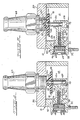
- valve assembly 10 having a rigid housing 12 with a flow passageway 14 therethrough adapted to communicate between an upstream system or fluid source, such as system to be evacuated (not shown), and a vacuum pump 16.
- valve means 18 in the housing 12 is movable between an open position ( Figure 4) spaced from the inlet orifice 20 to the fluid flow passageway 14, and a closed position ( Figure 5) blocking the flow of fluid at the inlet orifice.
- valve means 18 in the event of pump failure, back-flow is minimized by forcing the valve means 18 quickly into the closed position. This is achieved by venting ambient air, which is at a higher pressure than the air being evacuated, through an air passageway 22 and into a chamber 24 behind the valve means 18. The higher pressure air forces piston or plunger 26, which is slidably received therein, upwardly causing the sealing element 28 of the valve means to block orifice 20 against back-flow into the system being evacuated.
- the flow of ambient air into the chamber 24 is controlled by a diaphragm valve 30.
- high pressure hydraulic fluid or gas communicates through pressure port 32 to hold the normally open diaphragm in a closed position, sealing the ambient air passageway 22.
- the spring loaded diaphragm opens, permitting air to vent into the passageway 22 and forcing the valve means 18 to a closed position as described above. If, because of mechanical failure or the like the pump needs replacing, the entire valve assembly, or simply the housing top plate 34, with the valve means 18 held in place by suction, can be removed from the pump 16 without breaking the vacuum.
- valve means 18 when the pump resumes operation after an interruption, the valve means 18 does not immediately move to the open position.
- the higher pressure ambient air remaining in the passageway 22 and chamber 24 holds the valve means in a closed position, until sufficient air bleeds through the clearance between the piston or plunger 26 and the walls of the chamber 24 so as to allow the vacuum pump sufficient time to develop a relatively high vacuum, which reduces the momentary influx of contaminants into the system when the valve means 18 opens.
- Figure 1 depicts the valve assembly 10 of the present invention mounted atop a vacuum pump 16, of the type having an electric motor 36 in a direct drive relationship with rotary pumping elements (not shown) submerged in an oil bath within housing 38.
- the assembly 10 is mounted on pump support plate 40, so that the gas flow passageway 14 in the valve assembly communicates directly with the inlet to the pumping chambers.
- the pump itself may be of any type commonly used, e.g., a rotary vane pump, and the details of pump construction are not shown or discussed in detail herein.
- the valve assembly housing 12 is of generally two-part construction, with a substantially hollow body portion 42 which defines the interior flow passageway 14, and is closed at the top by the top plate 34.
- the underside of the valve body 42 is connected directly over the inlet to the vacuum pump 16 so as to communicate directly therewith.
- Gas from the system being evacuated enters the valve assembly 10 through the inlet orifice 20 in the top plate 34, which is shown threadedly receiving a connector 44 with a tapered outer end for insertion into rubber tubing or the like.
- an internal lateral support arm 46 extending from one wall of the body portion 42 supports the valve means 18 directly below the orifice 20.
- the valve means 18 is made up of the sealing element 28 and the piston or plunger 26, which is slidably received within the chamber 24 in the end of the support arm 46.
- the sealing element 28 is generally disc-shaped, and includes a flat support plate 48 of aluminum or other rigid material, covered with a layer of elastomeric or rubber-like material 50 such as neoprene, polyurethane or the like so as to provide a tight seal against the orifice 20.
- the sealing element 28 is attached to the piston or plunger 26 by a ball and socket joint wherein ball joint 52 at the upper end of the piston or plunger is received through a center opening in the support plate 48 and into a socket 54 in the elastomeric material 50.
- the plunger or piston 26 is preferably cylindrical, and chamber 24 is of like shape and is sized to permit slidable movement of the plunger up and down within the chamber.
- air pressure is employed in the present invention to aid in forcing the plunger 26 and sealing element 28 quickly upwardly to seal the orifice 20 against back-flow in the event of pump failure.
- the flow of ambient air between the air passageway 22, which leads to the chamber 24, and ambient air vent port 60 in the base portion 42 is controlled by the diaphragm valve 30, which is mounted in a large recess 58 in the body portion 42 of the housing.
- the air passageway 22 extends from the chamber 24, through the support arm 46, and through the center of the bottom surface 56 of the recess 58.
- the air vent port 60 also communicates through the bottom surface 56.
- the diaphragm valve 30 is mounted within the recess 58, with its peripheral edge resting on shoulder 62 which extends around the bottom inside edge of the recess, and supports the diaphragm above the bottom surface 56 of the recess. In this position, ambient air can communicate directly from the vent port 60 to the air passageway 22 through the space between the diaphragm 30 and the bottom surface 56 of the recess 58.
- the peripheral edge of the diaphragm 30 is compressively held in place against the shoulder 62 by a generally cylindrical insert 64 positioned within the recess 58 and locked in place by a snap ring 66.
- the insert 64 is of slightly smaller diameter than the recess and is sealed against the inside surface of the recess by it pair of space O-rings 68, which also serve to form an annular channel 70 between the insert and the inside surface of the recess.
- An internal T-shaped passageway 72 (shown in dashed lines in Figures 4 and 5) in the insert 64 extends from the side surface of the insert where it communicates with the annular channel 70 to the end surface of the insert where it opens immediately behind the diaphragm 30.
- the diaphragm 30 is normally maintained in a position spaced above the bottom surface 56 of the recess 58 by the force of a compressed coil spring 76 positioned within the ambient air passageway 22.
- pressurized fluid is applied through the high pressure access port 32 in the body portion 42 which communicates directly with the annular channel 70 around the insert 64.
- the fluid flows from channel 70, through the T-shaped insert passageway 72 and forces the diaphragm 30 against the chamfered end of the passageway 22, thereby sealing it against the entry of ambient air.
- this pressurized fluid is supplied by a bleed from the pressure side of the vacuum pump and it has been found that about 18 psig (1.26 kg/ cm 2 ) is sufficient to keep the diaphragm closed.
- the spring 76 returns the diaphragm to the normal open position, allowing ambient air to vent through the passageway 22 to the chamber 24.
- This diaphragm is preferably made of resilient rubber or elastomeric material which can withstand repeated flexing.
- the system to be evacuated is normally connected to the vacuum pump by flexible tubing, which may be received and clamped over the tapered end of the connector 44.
- the pump is then started, and gas flows from the system or source, through the connector 44, orifice 20 and passageway 14 in the valve housing 12, and into the pump.
- the valve means 18 is in the position illustrated in Figure 4, with the sealing element 28 spaced from the orifice 20, to allow air to be withdrawn from the system being evacuated.
- An output bleed of the pump is communicated through the high pressure access port 32 pressurizing the diaphragm on the opposite side of the spring 76 and forcing the diaphragm against the end of the passageway 22, thereby preventing entry of ambient air from the vent port 60.
- the sealing element 28 actually seals against the bottom edge of the insert member 44 which is threadedly received in the orifice 20 and extends slightly below the inside surface of the top plate 34. However, this is for the purpose of illustration only, and the sealing element 28 would seal the orifice 20 even without the presence of the insert member.
- valve assembly 10 or merely the top plate 34 may be removed simply by loosening bolts 80 which hold the assembly together and secured to the pump.
- the sealing element 28 remains held in tight contact against the orifice 20 by the vacuum in the evacuated system.
- the entire valve assembly 10 may be bolted to the new pump, or the top plate 34 and valve means 18 may be reconnected to a new body portion 42 provided on the new pump.
- the pump can be relatively easily changed or repaired without necessitating opening the evacuated system to ambient atmosphere.
- the valve means 18 Upon restarting the vacuum pump 16 after interruption, the valve means 18 does not automatically move to the open position. Before the valve means 18 can move to the open position, the ambient air trapped in the air passageway 22 and in the chamber 24 must be removed. Preferably, the clearance between the surfaces of the piston plunger 26 and chamber 24 is sufficiently small, less than or equal to about 0.002 inches (0.005 cm), to restrict the escape of the trapped ambient air therebetween. This results in a delay in the release of the valve means 18, which permits the vacuum pump 16 to draw a substantial vacuum before the valve opens, thereby reducing the brief influx of air or other contaminants into the evacuated system when the valve opens, and thereby minimizing the total back-flow which may occur in the event of interruption in the operation of the vacuum pump 16.
Landscapes
- Engineering & Computer Science (AREA)
- General Engineering & Computer Science (AREA)
- Mechanical Engineering (AREA)
- Compressors, Vaccum Pumps And Other Relevant Systems (AREA)
- Reciprocating Pumps (AREA)
- Fluid-Driven Valves (AREA)
- Details Of Valves (AREA)
Applications Claiming Priority (2)
| Application Number | Priority Date | Filing Date | Title |
|---|---|---|---|
| US06/195,874 US4366834A (en) | 1980-10-10 | 1980-10-10 | Back-flow prevention valve |
| US195874 | 1994-02-14 |
Publications (3)
| Publication Number | Publication Date |
|---|---|
| EP0062060A1 EP0062060A1 (en) | 1982-10-13 |
| EP0062060A4 EP0062060A4 (en) | 1983-02-09 |
| EP0062060B1 true EP0062060B1 (en) | 1985-05-15 |
Family
ID=22723176
Family Applications (1)
| Application Number | Title | Priority Date | Filing Date |
|---|---|---|---|
| EP19810902892 Expired EP0062060B1 (en) | 1980-10-10 | 1981-10-08 | Back-flow prevention valve |
Country Status (7)
| Country | Link |
|---|---|
| US (1) | US4366834A (enExample) |
| EP (1) | EP0062060B1 (enExample) |
| JP (1) | JPH0222273B2 (enExample) |
| CA (1) | CA1156122A (enExample) |
| DE (1) | DE3152349C2 (enExample) |
| GB (1) | GB2100839B (enExample) |
| WO (1) | WO1982001407A1 (enExample) |
Families Citing this family (14)
| Publication number | Priority date | Publication date | Assignee | Title |
|---|---|---|---|---|
| DE3150000A1 (de) * | 1981-12-17 | 1983-07-14 | Leybold-Heraeus GmbH, 5000 Köln | Oelgedichtete vakuumpumpe |
| DE3150033A1 (de) * | 1981-12-17 | 1983-07-14 | Leybold-Heraeus GmbH, 5000 Köln | Vakuumpumpe mit einem saugstutzen-ventil und betriebsverfahren dafuer |
| JPS61256153A (ja) * | 1985-05-08 | 1986-11-13 | 株式会社豊田自動織機製作所 | 車両空調装置 |
| IT1207829B (it) * | 1987-02-04 | 1989-06-01 | Galileo Spa Off | Perfezionamento nel circuito di lubrificazione delle pompe rotative per vuoto. |
| US4968221A (en) * | 1989-04-03 | 1990-11-06 | Dresser Industries, Inc. | Intake valve for vacuum compressor |
| DE4325283A1 (de) * | 1993-07-28 | 1995-02-02 | Leybold Ag | Betriebsabhängig steuerbares Ventilsystem für eine Vakuumpumpe |
| DE4336020C2 (de) * | 1993-10-22 | 1997-05-15 | Roediger Anlagenbau | Steueranordnung für ein durch Unterdruck betätigbares Absperrventil |
| DE19629137A1 (de) * | 1996-07-19 | 1998-01-22 | Gardena Kress & Kastner Gmbh | Steuereinrichtung für ein Fluid, wie Wasser |
| KR100408153B1 (ko) | 2001-08-14 | 2003-12-01 | 주식회사 우성진공 | 드라이 진공펌프 |
| US7836976B2 (en) * | 2005-10-20 | 2010-11-23 | Allied Construction Products, L.L.C. | Underground piercing tool |
| WO2011092930A1 (ja) * | 2010-01-29 | 2011-08-04 | アルバック機工株式会社 | ポンプ |
| ITBO20130351A1 (it) * | 2013-07-05 | 2015-01-06 | Gardner Denver S R L | Valvola di avviamento di una macchina operatrice a fluido funzionante in un impianto sottovuoto |
| US9587759B2 (en) | 2013-09-20 | 2017-03-07 | Itt Manufacturing Enterprises Llc | Quick release valve compressor |
| GB2549468B (en) * | 2016-04-14 | 2020-11-11 | Edwards Ltd | Protection valve |
Family Cites Families (11)
| Publication number | Priority date | Publication date | Assignee | Title |
|---|---|---|---|---|
| AT76256B (de) * | 1916-03-27 | 1919-04-25 | Arthur Ing Hardt | Luftkompressor. |
| US1684987A (en) * | 1927-11-03 | 1928-09-18 | Kellogg Mfg Co | Check valve |
| DE673497C (de) * | 1936-11-29 | 1939-03-23 | Leybold S Nachfolger E | Pumpe zur Erzeugung tiefer Druecke, insbesondere umlaufende OElluftpumpe |
| US2362750A (en) * | 1942-06-26 | 1944-11-14 | John T Hayward | Pumping apparatus |
| US2594132A (en) * | 1945-11-02 | 1952-04-22 | American Brake Shoe Co | Intake type unloader for compressors and the like |
| DE1266438B (de) * | 1960-01-04 | 1968-04-18 | Leybold Heraeus Gmbh & Co Kg | Sicherungsvorrichtung fuer Vakuumanlagen mit einem Verschlussventil |
| NL6402422A (enExample) * | 1963-03-18 | 1964-09-21 | ||
| GB1195361A (en) * | 1966-03-28 | 1970-06-17 | N G N Ltd | Improvements in and relating to Vacuum Pumping apparatus including a Rotary Vacuum Pump |
| US3406897A (en) * | 1966-07-18 | 1968-10-22 | Leybold Holding Ag | Mechanical vacuum pump |
| DE1775356B2 (de) * | 1968-08-01 | 1974-04-18 | Siemens Ag, 1000 Berlin U. 8000 Muenchen | Rückschlagventil |
| US4070001A (en) * | 1976-07-06 | 1978-01-24 | Musgrove Ronald R | Vacuum safety valve |
-
1980
- 1980-10-10 US US06/195,874 patent/US4366834A/en not_active Expired - Lifetime
-
1981
- 1981-10-08 WO PCT/US1981/001354 patent/WO1982001407A1/en not_active Ceased
- 1981-10-08 JP JP50337981A patent/JPH0222273B2/ja not_active Expired - Lifetime
- 1981-10-08 GB GB8213831A patent/GB2100839B/en not_active Expired
- 1981-10-08 DE DE19813152349 patent/DE3152349C2/de not_active Expired - Lifetime
- 1981-10-08 EP EP19810902892 patent/EP0062060B1/en not_active Expired
- 1981-10-09 CA CA000387717A patent/CA1156122A/en not_active Expired
Also Published As
| Publication number | Publication date |
|---|---|
| EP0062060A1 (en) | 1982-10-13 |
| US4366834A (en) | 1983-01-04 |
| JPS57501742A (enExample) | 1982-09-24 |
| DE3152349C2 (de) | 1996-07-11 |
| GB2100839B (en) | 1983-09-14 |
| JPH0222273B2 (enExample) | 1990-05-17 |
| EP0062060A4 (en) | 1983-02-09 |
| GB2100839A (en) | 1983-01-06 |
| DE3152349A1 (en) | 1982-12-16 |
| WO1982001407A1 (en) | 1982-04-29 |
| CA1156122A (en) | 1983-11-01 |
Similar Documents
| Publication | Publication Date | Title |
|---|---|---|
| EP0062060B1 (en) | Back-flow prevention valve | |
| US4526341A (en) | Pneumatic shut-off valve | |
| US4613111A (en) | Valve which is opened by reduced pressure | |
| KR20000035086A (ko) | 진공 압력 제어 장치 | |
| KR20090052851A (ko) | 밸브 다기관 조립체 | |
| GB1563329A (en) | Multiway valve | |
| EP1318303B1 (en) | A diaphragm-type pumping apparatus | |
| CA2389132C (en) | Pneumatic snap pilot | |
| US8066256B2 (en) | Valve actuator assembly | |
| KR102424593B1 (ko) | 리크감지 진공 공정용 아이솔레이션 밸브 | |
| US5002469A (en) | Switching device for reciprocating pumps | |
| US20030155541A1 (en) | Pressure enhanced diaphragm valve | |
| KR102022940B1 (ko) | 에어가압 유압장치용 논리크 에어 파일럿 유압 절환 밸브 | |
| US6026836A (en) | High pressure diaphragm valve | |
| US6073655A (en) | High pressure/vacuum isolation apparatus and method | |
| KR930000192B1 (ko) | 브레이크 제어밸브 | |
| US10578218B2 (en) | Vacuum valve | |
| KR101335097B1 (ko) | 에어 브리더 | |
| EP0978654B1 (en) | Safety valve apparatus for air pressure operable diaphragm pump | |
| US20180058453A1 (en) | Hermetic vacuum pump isolation valve | |
| JPH10122408A (ja) | 電磁弁及び電磁弁の制御方法 | |
| EP1092105B1 (en) | Automatic drain valve | |
| KR102548525B1 (ko) | 공기 압축기용 체크밸브 | |
| JPH0236958Y2 (enExample) | ||
| JP2517209Y2 (ja) | 流体切換弁 |
Legal Events
| Date | Code | Title | Description |
|---|---|---|---|
| PUAI | Public reference made under article 153(3) epc to a published international application that has entered the european phase |
Free format text: ORIGINAL CODE: 0009012 |
|
| AK | Designated contracting states |
Designated state(s): FR |
|
| 17P | Request for examination filed |
Effective date: 19821011 |
|
| GRAA | (expected) grant |
Free format text: ORIGINAL CODE: 0009210 |
|
| AK | Designated contracting states |
Designated state(s): FR |
|
| ET | Fr: translation filed | ||
| PLBI | Opposition filed |
Free format text: ORIGINAL CODE: 0009260 |
|
| 26 | Opposition filed |
Opponent name: LEYBOLD - HERAEUS GMBH Effective date: 19860213 |
|
| PLBN | Opposition rejected |
Free format text: ORIGINAL CODE: 0009273 |
|
| STAA | Information on the status of an ep patent application or granted ep patent |
Free format text: STATUS: OPPOSITION REJECTED |
|
| 27O | Opposition rejected |
Effective date: 19910910 |
|
| PGFP | Annual fee paid to national office [announced via postgrant information from national office to epo] |
Ref country code: FR Payment date: 20001009 Year of fee payment: 20 |
|
| APAH | Appeal reference modified |
Free format text: ORIGINAL CODE: EPIDOSCREFNO |