EP0062012A2 - Machine pour la fabrication de cadres, utilisant des agrafes angulaires - Google Patents
Machine pour la fabrication de cadres, utilisant des agrafes angulaires Download PDFInfo
- Publication number
- EP0062012A2 EP0062012A2 EP82830062A EP82830062A EP0062012A2 EP 0062012 A2 EP0062012 A2 EP 0062012A2 EP 82830062 A EP82830062 A EP 82830062A EP 82830062 A EP82830062 A EP 82830062A EP 0062012 A2 EP0062012 A2 EP 0062012A2
- Authority
- EP
- European Patent Office
- Prior art keywords
- machine
- frames
- thereafter
- fact
- joint
- Prior art date
- Legal status (The legal status is an assumption and is not a legal conclusion. Google has not performed a legal analysis and makes no representation as to the accuracy of the status listed.)
- Withdrawn
Links
Images
Classifications
-
- B—PERFORMING OPERATIONS; TRANSPORTING
- B27—WORKING OR PRESERVING WOOD OR SIMILAR MATERIAL; NAILING OR STAPLING MACHINES IN GENERAL
- B27F—DOVETAILED WORK; TENONS; SLOTTING MACHINES FOR WOOD OR SIMILAR MATERIAL; NAILING OR STAPLING MACHINES
- B27F7/00—Nailing or stapling; Nailed or stapled work
- B27F7/02—Nailing machines
- B27F7/025—Nailing machines for inserting joint-nails
Definitions
- This invention concerns a machine to joint frames.
- the invention concerns a machine to joint frames by using angular clips of a special shape of which the sides are located along the frames to be jointed, and also concerns the angular clips of the invention.
- Machines to joint frames which use metal clips inserted perpendicularly to the line of the joint of the frames to be united.
- One known type of these jointing machines consists of a movable clamping plate solidly fixed to two vertical guiding uprights, which slide within guiding sleeves fixed to the work bench and are anchored at one of their ends to a lower plate which is located below the work bench and bears a pneumatic jack, whereby the upper end of said jack is equipped with a jointing head able to receive jointing clips from a knurled metal tape coming from a bobbin positioned at the side of said device and beneath the work bench on which the frames are arranged with a suitable guide.
- the lower plate when the jack is acftua ted the lower plate is thrust downwards and thereby lowers the upper plate, which thus compresses and clamps the frames to be jointed.
- This known jointing machine entails various shortcom-. ings. One of them is the overall bulk of the jointing ma- . chine and the need to have a work bench to which the machine is secured.
- Such knurled clips thus located diagonally to the frames require also that the jack should give them a heavy thrust, which can possibly damage the frames themselves, . especially so if the frames are made of soft wood, since said clips are applied substantially diagonally in relation to the fibres of the wood, which therefore opposes a stronger resistance to penetration.
- the known jointing machines are therefore not suitable for jointing frames made of a not very hard wood.
- a purpose of our invention is to embody a jointing machine able to eliminate the aforesaid shortcomings and drawback.
- Another purpose is to embody triangular clips of a special shape for use together with the jointing machine of our invention.
- An advantage of the invention is to obtain a stiffer joint.
- Another advantage is that such a stiffer joint can be made both with frames made of soft wood and with frames having a minimum width starting at 5 mm., without any damage to said frames.
- jointed frames can be of a type with a lengthwise groove, whereby .the angular clips of the invention are located in said grooves along the fibres of the wood.
- Yet another advantage is the modest overall size of the jointing machine of the invention and the fact that it is portable, these being factors which have a favourable effect .on the overall cost of the machine and its usefulness.
- the invention is therefore embodied with a machine us- .ing angular clips to joint frames, said machine being characterized by comprising in mutual cooperation and coordination:
- said drive means for the vertical movement of the clamping plate consist of one or more pneumatic jacks having . their upper end anchored to the upper side of the framework, whereas the ends of their relative stems are secured to said clamping plate.
- the jack means which drive said pointed head also consist of a pneumatic jack anchored in an upright manner to the middle of the surface of said plate, whereby the upper end of the jack has means which regulate the travel of the plate and which cooperate with the upper side of said framework, and whereby the jack bears said triangular point on its own stem.
- vertical guide means are envisaged which can guide the thrusting point during insertion of the clips
- abutting means are also envisaged which can,hold packs of clips of various heights within the store in the right position in relation to the path of the thrusting point.
- the clips of the invention are triangular and each of them has two symmetrical arms which can hold a corner between them and are joined together with a small middle portion, which is substantially flat and forms the same angle with each arm; the outer ends of said arms are provided with an edge bent outwards.
- the middle portion comprises one or more shallow grooves.
- the presence of the flat middle portion provided in said clips gives a stronger joint.
- Said flat portion also serves to guide the clip vertically during its insertion in the frame, being supported at its back by the pack from which it is being detached.
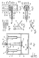
- I0 indicates the jointing .machine of the invention: II is the containing framework and I2 is the clamping plate which runs within the upright .guides III provided in the upright sides of the framework II: I3 are drive means which can move the plate I2 and con- .sist,in this instance, of two pneumatic jacks II3 anchored .to the upper side of the framework II, their stems 2I3 being solidly fixed to the plate I2; said means I3 can be replaced with one single jack located in the middle of the plate I2.
- the clamping plate I2 bears at its middle the means I4 for applying angular clips I5; said means I4 (shown in Figs. 2 and 3) comprise a store I6 for the pack II5 of angular clips and a head I7 with a triangular point 2I, whereby the store I6 and head I7 are located below said plate I2; said means I4 also comprise means I8 to drive said head means I7, said means I8 being in this instance a pneumatic jack anchored to the upper surface of said plate 12; the opposite end of said jack I8 comprises the part II8 which cooperates with the upper side of the framework II through the means I9 that regulate the travel of the plate I2; said regulating means I9 consist of a threaded portion II9 of the part II8 passing through a hole 2II provided on the upper side of the framework II and also consist of a flanged abutting knob 2I9 screwed onto said threaded portion II9.
- the vertical position of the flanged abutting knpb 2I9 is adjusted so that it rests on the outer surface of the upper side of the framework, thus hindering the further forward movement of the plate and determining the end of the run thereof. This procedure prevents the plate I2 from buckling the frame to be jointed.
- the means I4 which ap- ply the clips consist of one single support 20 located beneath the plate I2 and having a middle part 2I0 which comes into contact with the joint when the clamping plate I2 goes down, and also having a part 320 which juts out sideways.
- the jutting part has a groove 420 which forms the store of the pack II5 loaded by means of the spring I6.
- Said groove 420 communicates with an upright hole 520 having a rectangular section and located in the middle part. ,220 of the support 20.
- the pressure means 25 consist of a sliding block I25 lodged above the groove 420 and equipped with an inducting surface 225 and with thrust spring means 325 . able to keep it pressed against the upper surface of the pack II5.
- the plate I2 includes a hole II2 through which passes a stem 2I8 of the pneumatic jack I8, to which is anchored the head I7 with its point having a triangular section 2I; said head I7 is guided by the walls of the hole 520 and is able to detach one angular clip I5 at a time from the pack II5 and to apply it to the joint of the frame 2I5 already clamped by the plate 12 by means of the middle part 220 of the. support 20 in suitably shaped means 22 anchored to the base of the framework II so as to position the frames to be jointed.
- Said point having a triangular section is equipped at. its side with a jutting surface 26 able to cooperate with a groove 27 provided in said hole 520 so as to guide the des - cent of said point 2I still farther.
- the fixed part of the jacks II3 can be anchored below to the base holding. the frames to be jointed, said jacks II3 can be operated so as to contract instead of extending for the descent of the clamping plate I2, the means I4 applying the clip I5 can be located upside down below said base holding the frames to be jointed and a hole can be provided in said base which will be the natural continuation of the hole 520.
- the clip is inserted into the .joint from underneath, thereby permitting advantageously, in .the case of frames having a complex section, the support of .the frames on said base by means of the flat rear surface of .the frames, thus retaining all the advantages belonging to .the preferential embodiment.
- the clips of the invention are .triangular and each of them has two symmetrical arms 7I5 to .hold a corner between them; said arms 7I5 are connected to- .gether with a small middle portion 4I5 which is substantial- .ly flat and forms the same angle with each arm 7I5; said arms 7I5 are equipped at their outer end with an edge 3I5 bent .outwards.
- the middle portion .4I5 of the clip I5I has one or more shallow grooves 6I5.
- the presence of said flat middle. .portion 6I5 envisaged in said clips I5I gives a stronger .joint.
- Said flat portion 4I5 also serves to guide the clip I5- .I5I vertically while it is entering the frame 2I5 and is be- .ing supported at its back by the pack II5 from which it is . .being detached.
- Said shaped means for positioning the frames are shown. .in Fig.4 and consist of a bar having a frontal angled shape. .able to position the frames in relation to each other in the .jointing position shown in Fig.5.
- Said shaped positioning means 22 are provided with a .portion 222 shaped like the form of the joint and with an aJ- .ignment arm 322 stretching rearwards in relation to said .shaped portion 222 and cooperating with guide means 23 secured to the framework, whereby said guide means are equipped .with clamping means 24 consisting of a locking screw I24 .able to clamp said alignment arm within the guide means 23.
- the pneumatic means are pro- .vided with suitable actuation and control means, which are .helpfully of a known pedal type and are therefore not shown.
- the clips I5 are .angled and comprise outwardly bent end edges able to hinder .displacement of the relative sides of the clip after its ap- .plication; said edges also cooperate with grooves provided .in the head so as to guide the clip while the latter is go- .ing downwards.
- the front and perhaps also the ream side of the jointing machine will be equipped with a sheet metal cover.
- this cover will leave uncovered the lower. part, which will instead be closed with a transparent cover, thus allowing the machine operator to check the prior positioning and execution of the joint visually.
- the means I4 which apply the clip I5 are now operated with the drive of the pneumatic jack I8.
- the clips I5 can .be right-angled or else can be formed at any angle between .30 and I50 degrees.
- the shaped positioning means 22 can have a positioning shape 222 which is not right-angled but is comprised between 30 and I50 degrees to suit the type of .frame to be formed, that is, so as to enable a joint to be .made between parts of the frame which are sloped but not per- .pendicular to each other.
Landscapes
- Engineering & Computer Science (AREA)
- Mechanical Engineering (AREA)
- Life Sciences & Earth Sciences (AREA)
- Forests & Forestry (AREA)
- Basic Packing Technique (AREA)
- Clamps And Clips (AREA)
Applications Claiming Priority (2)
| Application Number | Priority Date | Filing Date | Title |
|---|---|---|---|
| ITUD1981U60347U IT8160347U1 (it) | 1981-03-24 | 1981-03-24 | Giuntatrice a graffe angolari per cornici |
| IT6034781U | 1981-03-24 |
Publications (2)
| Publication Number | Publication Date |
|---|---|
| EP0062012A2 true EP0062012A2 (fr) | 1982-10-06 |
| EP0062012A3 EP0062012A3 (fr) | 1984-04-04 |
Family
ID=11290395
Family Applications (1)
| Application Number | Title | Priority Date | Filing Date |
|---|---|---|---|
| EP82830062A Withdrawn EP0062012A3 (fr) | 1981-03-24 | 1982-03-18 | Machine pour la fabrication de cadres, utilisant des agrafes angulaires |
Country Status (2)
| Country | Link |
|---|---|
| EP (1) | EP0062012A3 (fr) |
| IT (1) | IT8160347U1 (fr) |
Cited By (1)
| Publication number | Priority date | Publication date | Assignee | Title |
|---|---|---|---|---|
| FR2550121A1 (fr) * | 1983-08-04 | 1985-02-08 | Cassese Antoine | Dispositif pour assembler par agrafage des moulures a plusieurs feuillures |
Family Cites Families (14)
| Publication number | Priority date | Publication date | Assignee | Title |
|---|---|---|---|---|
| US2530626A (en) * | 1949-01-18 | 1950-11-21 | Gen Nailing Mach | Nailing chuck actuating mechanism |
| US2596181A (en) * | 1949-07-20 | 1952-05-13 | E B Packard Co Inc | Wood fastener |
| CH224605A (de) * | 1951-07-26 | 1942-12-15 | Koeberle Albert | Verbindungsorgan für miteinander zu vereinigende Holzteile. |
| US2782673A (en) * | 1952-03-10 | 1957-02-26 | E B Packard Co Inc | Multi-pronged sheet metal corner fastener |
| US2714208A (en) * | 1953-11-20 | 1955-08-02 | Bostitch Inc | Stapling implement |
| US2900638A (en) * | 1954-03-23 | 1959-08-25 | O'kelley O'dell | Apparatus for driving joint nails |
| US2903699A (en) * | 1957-01-11 | 1959-09-15 | Mazzola Anthony | Clamp nailing apparatus |
| US2987724A (en) * | 1958-08-25 | 1961-06-13 | Terrell Mach Co | Joint nailing mechanism |
| US3431810A (en) * | 1967-08-07 | 1969-03-11 | Hugh Black | Wood fasteners |
| US3734381A (en) * | 1971-03-10 | 1973-05-22 | H Blevio | Apparatus for adhering and interlocking mitered molding strips to a panel |
| SE371128B (fr) * | 1971-08-02 | 1974-11-11 | K Charlez | |
| IT1029093B (it) * | 1975-04-08 | 1979-03-10 | Motta A | Macchina per unire fra di loro liste di legno |
| FR2318715A1 (fr) * | 1975-07-22 | 1977-02-18 | Cassese Antoine | Dispositif d'agrafage et agrafe, notamment pour cadres de bois |
| DE2919564A1 (de) * | 1979-05-15 | 1980-11-27 | Alfredo Motta | Vorrichtung zum zusammenfuegen von leisten aus holz o.dgl. mit stumpfer stossverbindung |
-
1981
- 1981-03-24 IT ITUD1981U60347U patent/IT8160347U1/it unknown
-
1982
- 1982-03-18 EP EP82830062A patent/EP0062012A3/fr not_active Withdrawn
Cited By (3)
| Publication number | Priority date | Publication date | Assignee | Title |
|---|---|---|---|---|
| FR2550121A1 (fr) * | 1983-08-04 | 1985-02-08 | Cassese Antoine | Dispositif pour assembler par agrafage des moulures a plusieurs feuillures |
| EP0133404A1 (fr) * | 1983-08-04 | 1985-02-20 | Antoine Cassese | Dispositif pour assembler par agrafage des moulures à plusieurs feuillures |
| US4817965A (en) * | 1983-08-04 | 1989-04-04 | Antoine Cassese | Device for assembling, by clipping, moldings incorporating several rabbets |
Also Published As
| Publication number | Publication date |
|---|---|
| IT8160347V0 (it) | 1981-03-24 |
| IT8160347U1 (it) | 1982-09-24 |
| EP0062012A3 (fr) | 1984-04-04 |
Similar Documents
| Publication | Publication Date | Title |
|---|---|---|
| US4516452A (en) | Paper cutter | |
| US3862583A (en) | Bandsaw machines provided with an improved material holding vise | |
| US3147791A (en) | Brake for bending sheet metal | |
| EP0062012A2 (fr) | Machine pour la fabrication de cadres, utilisant des agrafes angulaires | |
| US3292477A (en) | Tape splicer | |
| KR920011891A (ko) | 곤포(梱包)장치 | |
| US3709079A (en) | Film splicer | |
| US20050263566A1 (en) | Substrate holding apparatus | |
| CN210945970U (zh) | 一种皮草加工用高效钉扣机 | |
| US2755473A (en) | Means for loading fasteners in stapling devices | |
| US4039108A (en) | Feeding and hold down mechanism for a sanding and shaping machine | |
| US4112839A (en) | Apparatus for connecting the tying means ends on tying machines | |
| CN210099116U (zh) | 一种包装设计用割样工作台 | |
| CN215145727U (zh) | 一种镜面激光脱漆打标机 | |
| US2245472A (en) | Presser plate for dispensing machine feed tables | |
| US3413668A (en) | Paper padding and transport device | |
| US2025998A (en) | Shoe lasting machine | |
| CN210361781U (zh) | 一种封边定高装置 | |
| CN220217176U (zh) | 一种激光切割夹具 | |
| US1910633A (en) | Nail guiding means | |
| CN110744279B (zh) | 组装装置 | |
| CN214022884U (zh) | 一种铁片送料冲切装置 | |
| CN216066073U (zh) | 一种激光切割模板 | |
| CN213566625U (zh) | 一种茶叶盒压膜装置 | |
| US4011646A (en) | Apparatus for attaching flexible parts and/or innersoles with joint springs through riveting |
Legal Events
| Date | Code | Title | Description |
|---|---|---|---|
| PUAI | Public reference made under article 153(3) epc to a published international application that has entered the european phase |
Free format text: ORIGINAL CODE: 0009012 |
|
| AK | Designated contracting states |
Designated state(s): AT BE CH DE FR GB LU NL SE |
|
| 17P | Request for examination filed |
Effective date: 19831102 |
|
| PUAL | Search report despatched |
Free format text: ORIGINAL CODE: 0009013 |
|
| AK | Designated contracting states |
Designated state(s): AT BE CH DE FR GB LI LU NL SE |
|
| STAA | Information on the status of an ep patent application or granted ep patent |
Free format text: STATUS: THE APPLICATION HAS BEEN WITHDRAWN |
|
| 18W | Application withdrawn |
Withdrawal date: 19840806 |
|
| RIN1 | Information on inventor provided before grant (corrected) |
Inventor name: MUSCI, REMIGIO |