EP0061978B1 - Quadraturauslösungssystem zur intermittierenden Kraftstoffeinspritzung - Google Patents
Quadraturauslösungssystem zur intermittierenden Kraftstoffeinspritzung Download PDFInfo
- Publication number
- EP0061978B1 EP0061978B1 EP82400605A EP82400605A EP0061978B1 EP 0061978 B1 EP0061978 B1 EP 0061978B1 EP 82400605 A EP82400605 A EP 82400605A EP 82400605 A EP82400605 A EP 82400605A EP 0061978 B1 EP0061978 B1 EP 0061978B1
- Authority
- EP
- European Patent Office
- Prior art keywords
- pulses
- cam member
- pulse
- binary valued
- engine
- Prior art date
- Legal status (The legal status is an assumption and is not a legal conclusion. Google has not performed a legal analysis and makes no representation as to the accuracy of the status listed.)
- Expired
Links
- 239000000446 fuel Substances 0.000 title claims description 12
- 238000002347 injection Methods 0.000 title claims description 11
- 239000007924 injection Substances 0.000 title claims description 11
- 230000001133 acceleration Effects 0.000 claims description 11
- 238000002485 combustion reaction Methods 0.000 claims description 8
- 230000002146 bilateral effect Effects 0.000 description 6
- 230000005355 Hall effect Effects 0.000 description 3
- 238000010586 diagram Methods 0.000 description 2
- 238000000034 method Methods 0.000 description 2
- 235000014676 Phragmites communis Nutrition 0.000 description 1
- 230000003321 amplification Effects 0.000 description 1
- 230000000712 assembly Effects 0.000 description 1
- 238000000429 assembly Methods 0.000 description 1
- 239000003990 capacitor Substances 0.000 description 1
- 238000003199 nucleic acid amplification method Methods 0.000 description 1
- 230000003287 optical effect Effects 0.000 description 1
- 230000001360 synchronised effect Effects 0.000 description 1
- 230000007704 transition Effects 0.000 description 1
- 230000001960 triggered effect Effects 0.000 description 1
Images

Classifications
-
- F—MECHANICAL ENGINEERING; LIGHTING; HEATING; WEAPONS; BLASTING
- F02—COMBUSTION ENGINES; HOT-GAS OR COMBUSTION-PRODUCT ENGINE PLANTS
- F02D—CONTROLLING COMBUSTION ENGINES
- F02D41/00—Electrical control of supply of combustible mixture or its constituents
- F02D41/30—Controlling fuel injection
- F02D41/32—Controlling fuel injection of the low pressure type
- F02D41/36—Controlling fuel injection of the low pressure type with means for controlling distribution
-
- Y—GENERAL TAGGING OF NEW TECHNOLOGICAL DEVELOPMENTS; GENERAL TAGGING OF CROSS-SECTIONAL TECHNOLOGIES SPANNING OVER SEVERAL SECTIONS OF THE IPC; TECHNICAL SUBJECTS COVERED BY FORMER USPC CROSS-REFERENCE ART COLLECTIONS [XRACs] AND DIGESTS
- Y02—TECHNOLOGIES OR APPLICATIONS FOR MITIGATION OR ADAPTATION AGAINST CLIMATE CHANGE
- Y02T—CLIMATE CHANGE MITIGATION TECHNOLOGIES RELATED TO TRANSPORTATION
- Y02T10/00—Road transport of goods or passengers
- Y02T10/10—Internal combustion engine [ICE] based vehicles
- Y02T10/40—Engine management systems
Definitions
- This invention relates in general to electronic fuel injection systems for internal combustion . engines and in particular to a sensor and digital control means for generating sequential timing signals.
- U.S. Patent 3,575,146 issued to Creighton et al teaches a three switch (sensor), one cam system for determining the ignition or injection times in internal combustion engines. This system is duplicated for each cylinder in the engine.
- U.S. Patent 3,738,339 issued to Huntzinger et al teaches a two sensor, two cam system for determining the ignition time for each cylinder.
- One sensor determines a predetermined number of degrees before the top-dead center position of each cylinder and the other sensor responds to a multi-toothed cam to determine each degree of rotation of the engine crankshaft.
- a distributor as shown in reference U.S. patent 3,605,713, cited in Col. 2 of 3,738,339, to direct the ignition pulse to the correct spark plug.
- U.S. Patent 3,710,763 issued to Bassot et al discloses a switch for each injector plus a synchronizing switch for synchronizing the time of operation of each of the high speed injectors to a corresponding predetermined angular position of the engine camshaft.
- U.S. Patent 3,702,601 issued to Gordon et al discloses the use of four switches to generate eight pulses each engine cycle and one switch to indicate each half of the engine cycle. Thus, five switches are required to generate the eight actuation pulses.
- WO-A-81/00433 describes a device for controlling ignition timing comprising a rotary member having a portion with a different electrical property on one part of its periphery.
- US-A-4,150,653 describes a phase-controlled pulse signal generator comprising a magnetic field source on a rotating shaft, and a Hall effect sensor submitted to the field, the sinusoidal signal delivered being processed by a phase correcting circuit controlled by the speed of the shaft, followed by a triggered pulse circuit.
- the classical technique, as is illustrated in the prior art, for triggering an ignition system is also used in triggering or controlling a sequential fuel injection system.
- This technique utilizes two sensors such as magnetic reed switches to provide two separate signals to a counting circuit.
- one switch provides a synchronization signal for initializing the counter which signal occurs once per engine cycle and is typically indicative of the number one cylinder.
- the other switch generates clocking signals to count a divide-by-four counter for generating four actuation pulses per engine cycle to initiate the proper injection pulses.
- the synchronizing signal assures that the counter states are synchronized with the correct cylinder during the engine cycle. Thus, with two sensors, synchronization does not happen until the synchronizing pulse is generated which may be one complete engine cycle after engine turn-on.
- FR-A-2 332 433 describes a system for controlling the timing of fuel injection valves for an internal combustion engine and includes three sensors equally spaced about a rotating cam member.
- EP-A-0 024 233 describes a sequential fuel injection system as defined in the preamble to claim 1 and which includes two Hall effect devices arranged adjacent a cam member. Located on the cam member are a plurality of elements generating actuation signals and one dissimilar element which produces a synchronisation pulse. With this system the actual position is known after 720° of rotation.
- a quadrature trigger system for a four cylinder sequential fuel injection system for synchronising the injectors with the first ninety degrees of rotation of a shaft of an internal combustion engine rotating once for each engine cycle, comprising a cam member adapted for rotation with the shaft, and two proximity sensors mounted relative to said cam member, characterized in that the shaft is a camshaft, the cam member is a semicircular single lobed cam, and the two proximity sensors are positioned ninety degrees apart and are each responsive to said cam member for generating a binary valued code sequence pulses with a pulse width time equal to the time said cam member is in sensing proximity to each of said sensors;
- decoding means including exclusive-OR gating and inverting means responsive to said binary valued code sequence pulses for doubling the frequency of said binary valued code sequence pulses;
- two pulse generators responsive to engine operating conditions for generating injector actuator pulses and operative in response to said double frequency pulses and said binary valued code sequence pulses for supplying alternate injector actuator pulses for selecting, within the first ninety degrees of rotation of the camshaft, the first of said injectors.
- the quadrature trigger system for a sequential fuel injection system or for an ignition system of an internal combustion engine 10 is a binary quadrature system.
- the number of sequential events is equal to 2n where "n" is the number of switch assemblies required.
- the quadrature trigger system is for a four cylinder internal combustion engine and therefore "n" equals two.
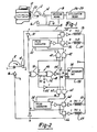
- Fig. 1 is a schematic block diagram illustrating the relationship of the quadrature trigger system with an engine 10.
- the quadrature trigger system comprises a cam 12, two proximity sensors 14,16 and a decoding means 18 for generating four pulses, one for each individual sequential event.
- the cam 12 is a single lobe cam adapted for rotation with the camshaft 20 of the engine.
- the camshaft rotates once per each engine cycle.
- the single lobe has a rotational timing of one hundred eighty degrees and is therefore a semicircular cam.
- the two proximity sensors 14, 16 may be hall- effect devices which are positioned ninety degrees apart and in sensing relationship to the periphery of the cam. Each sensor will generate a first binary valued signal when in a sensing relationship the cam and an opposite binary valued signal at all other times. In the embodiment of Fig. 1, each sensor will generate a binary one valued signal for one-half of an engine cycle and will overlap each other for one-quarter of an engine cycle.
- the proximity switches may be the equivalent of single pole double throw switches having an actuating arm in contact with the lobe on the cam or may be an optical device instead of the hall-effective device.
- the decoding means 18 is an electronic circuit having two pulse generators 22, 24 each generating pulses for two sequential events or injectors 26, 27, 28, 29. Interconnecting the pulse generators 22, 24, the sensors 14, 16 and injectors 26-29 is a combination of logic elements for sorting and directing various control voltages for generating pulses for the injectors.
- the pulse generating means 30 includes acceleration enrichment means for generating acceleration pulses upon demand. The logic elements respond to the acceleration pulses and add the pulse time of these pulses to the injector pulses to thereby increase the amount of fuel injected into the engine. It is understood that as is well known, the time of the pulse width of the injector pulses is proportional to the amount of fuel injected into the engine.
- the operation of the quadrature trigger system of the preferred embodiment is as follows.
- the problem solved in this embodiment is the proper generation of a particular fuel injector actuated pulse within one-quarter of an engine cycle upon engine turn on. This requires a decoding circuitry to initiate and multiplex the pulse and amplification stages to the proper injector.
- the single lobe cam 12, as it rotates relative to the two proximity switches 14, 16 generates the pulses shown in Fig. 3A and 3B. These pulses are illustrated as square waves and each have a duration equal to one-half an engine cycle and are out of phase with each other by one-quarter of a cycle. For the purposes of description, the actuation of injectors one 26 and three 27 will be illustrated.
- the switch means 14 corresponding to injectors one and three generates the pulse illustrated in Fig. 3A.
- This pulse is supplied to the input of a digital inverter 32 and to the control gate of a first bilateral switch 34.
- the output of the digital inverter 32, Fig. 3C is connected to the control gate of a second bilateral switch 36 and to one input of a two input exclusive OR gate 38.
- the second input to the exclusive OR gate 38 is the inverted pulse Fig. 3D from the switch means 16 corresponding to injectors two 28 and four 29.
- the output of the exclusive OR gate 38 is a square wave pulse Fig. 3E of twice the frequency of the pulse generated by either of the switch means 14, 16.
- the output pulse of the exclusive OR gate 38 is supplied to one input of each of two NAND gates 40, 42 in the control circuit for injectors one and three, to the input of a first digital inverter 44 and to the input of a one-shot circuit 46.
- the one-shot circuit 46 in the preferred embodiment comprises a second two input exclusive OR gate 48 where one input receives the output of first exclusive OR 38 gate and the second input has a resistor 50 and a capacitor 52 electrically connected to the output of the first exclusive OR gate 38.
- the output of the second exclusive OR gate 48 is electrically connected to a second digital inverter 54 having its output signal, Fig. 3G, applied to the interrupt input 56 of a microprocessor 58 such as an Intel 8048.
- the output of the first digital inverter 44, Fig. 3F is connected to an input of each of two NAND gates 60, 62 in the control circuit for injectors two 28 and four 29.
- the microprocessor 58 is programmed to receive inputs from several sensors, not shown, and to generate several control signals, one of which is called Beta Set as shown in Fig. 3H. This signal which occurs four times each engine cycle, indicates the start of an injector pulse as shown in Figs. 3Q through 3T.
- the Beta Set signal is supplied to the second input of one of the two NAND gates 42, 62 in the control circuits for each injector group.
- the output signal of these NAND gates 42,62 shown in Fig. 31 or 3J is supplied either one of two pulse generators 22, 24 to generate the properlytimed pulseforthe respective injectors.
- the output pulse of the pulse generators 22, 24, Fig. 3N or 3P is shown in the first half of the Figs.
- the pulse generator output pulse is amplified and in the case of injectors one and three, is supplied to the input of the first and second bilateral gates 34, 36.
- the pulse generator pulse is applied to actuate the appropriate injector coil.
- the logic levels are incorrect so the output of the bilateral switches 34, 36 is inverted to provide a ground level to the coil 26, 27 to be activated.
- the pulse generator 24 generates a properly timed pulse to either of the bilateral switches 64, 66 and under control of signal generated by the second switch means 16 will cause actuation of either of the second or fourth injector 28, 29.
- the microprocessor 58 calculates an acceleration enrichment operation for the engine 10 and generates an acceleration enrichment signal Fig. 3K.
- This signal is applied to the second input of the other of the two NAND gates 40, 60 in the control circuits for each injector group.
- the output signal of these NAND gates 40, 60 is respectively illustrated in Figs. 3L and 3M.
- These signals, Figs. 3L and 3M are inputted to the two pulse generators 22,24 and the respective output pulses therefrom are longer in time by the amount of time of the acceleration enrichment pulse width.
- This acceleration-enriched pulse generator output pulse is shown in the second half of Figs. 3N and 3P.
- the decoding means will decode these signals and in response to proper control signals from a microprocessor, direct the correct injector actuated signal in the proper time sequence to correct injector. Synchronization ofthe output of the microprocessorto the proper injector requires only one transition of the binary level signals from either of the proximity switches.
Landscapes
- Engineering & Computer Science (AREA)
- Chemical & Material Sciences (AREA)
- Combustion & Propulsion (AREA)
- Mechanical Engineering (AREA)
- General Engineering & Computer Science (AREA)
- Electrical Control Of Air Or Fuel Supplied To Internal-Combustion Engine (AREA)
- Fuel-Injection Apparatus (AREA)
Claims (3)
Applications Claiming Priority (2)
| Application Number | Priority Date | Filing Date | Title |
|---|---|---|---|
| US06/249,772 US4372273A (en) | 1981-04-01 | 1981-04-01 | Quadrature trigger system for sequential fuel injection |
| US249772 | 1994-05-26 |
Publications (3)
| Publication Number | Publication Date |
|---|---|
| EP0061978A2 EP0061978A2 (de) | 1982-10-06 |
| EP0061978A3 EP0061978A3 (en) | 1984-06-20 |
| EP0061978B1 true EP0061978B1 (de) | 1988-03-09 |
Family
ID=22944928
Family Applications (1)
| Application Number | Title | Priority Date | Filing Date |
|---|---|---|---|
| EP82400605A Expired EP0061978B1 (de) | 1981-04-01 | 1982-04-01 | Quadraturauslösungssystem zur intermittierenden Kraftstoffeinspritzung |
Country Status (5)
| Country | Link |
|---|---|
| US (1) | US4372273A (de) |
| EP (1) | EP0061978B1 (de) |
| JP (1) | JPS582437A (de) |
| DE (1) | DE3278216D1 (de) |
| ES (1) | ES8303612A1 (de) |
Families Citing this family (6)
| Publication number | Priority date | Publication date | Assignee | Title |
|---|---|---|---|---|
| BR8600316A (pt) * | 1985-01-28 | 1986-10-07 | Orbital Eng Pty | Processo de dosagem de combustivel e processo e aparelho para alimentar uma quantidade dosada de combustivel liquido,em um sistema de injecao de combustivel |
| FR2637652B1 (fr) * | 1988-10-11 | 1993-12-31 | Bendix Electronics Sa | Dispositif de reperage d'un cycle de fonctionnement d'un moteur a combustion interne |
| US5263678A (en) * | 1990-04-23 | 1993-11-23 | Norbac Corporation | Apparatus for periodically displacing a display terminal |
| JPH0642400A (ja) * | 1992-07-24 | 1994-02-15 | Yamaha Motor Co Ltd | 燃料噴射制御装置 |
| JP3828239B2 (ja) * | 1997-05-22 | 2006-10-04 | 三菱電機株式会社 | 燃料噴射用インジェクタの制御装置 |
| US8386108B2 (en) | 2011-03-02 | 2013-02-26 | Bombardier Transportation Gmbh | System and method of controlling supply voltage polarity on a vehicle |
Citations (2)
| Publication number | Priority date | Publication date | Assignee | Title |
|---|---|---|---|---|
| WO1981000433A1 (fr) * | 1979-08-07 | 1981-02-19 | Mitsubishi Electric Corp | Dispositif de commande de reglage de l'allumage |
| EP0024233A2 (de) * | 1979-08-13 | 1981-02-25 | The Bendix Corporation | System für aufeinanderfolgende Kraftstoffeinspritzung mit überlappender Betätigung der Einspritzventile |
Family Cites Families (12)
| Publication number | Priority date | Publication date | Assignee | Title |
|---|---|---|---|---|
| SE349097B (de) * | 1966-04-13 | 1972-09-18 | Sopromi Soc Proc Modern Inject | |
| US3612009A (en) * | 1968-08-28 | 1971-10-12 | Toyota Motor Co Ltd | Fuel injection synchronizing system |
| US3575146A (en) * | 1969-02-06 | 1971-04-20 | Physics Int Co | Fuel injection system for an internal combustion engine |
| US3759231A (en) * | 1970-05-07 | 1973-09-18 | Nippon Denso Co | Electrical fuel injection control system for internal combustion engines |
| US3702601A (en) * | 1971-06-11 | 1972-11-14 | Gen Motors Corp | Electronic fuel injection system |
| US3738339A (en) * | 1971-12-06 | 1973-06-12 | Gen Motors Corp | Electronic ignition spark advance system |
| FR2171626A5 (de) * | 1972-02-09 | 1973-09-21 | Schlumberger Compteurs | |
| US3881453A (en) * | 1973-10-01 | 1975-05-06 | Bendix Corp | Electronic fuel injection triggering means |
| DD127770A1 (de) * | 1975-11-18 | 1977-10-12 | Gerhard Haase | EINRICHTUNG ZUM TAKTRrCHTIGEN STEUERN VON ELEKTROMAGNETISCHEN EINSPRITZVENTILEN FUER MEHRZYLINDER-VIERTAKTVERBRENNUNGSMOTOREN |
| US4009699A (en) * | 1976-01-19 | 1977-03-01 | General Motors Corporation | Digital ignition spark timing angle control with read only memory |
| FR2345755A1 (fr) * | 1976-02-04 | 1977-10-21 | Thomson Csf | Systeme utilisant un element magnetosensible pour engendrer un signal electrique en synchronisme avec le mouvement periodique d'une piece, et application aux moteurs a combustion interne |
| IT1124715B (it) * | 1976-09-06 | 1986-05-14 | Alfa Romeo Spa | Impianto di iniezione intermittente di combustibile per motori a scoppio |
-
1981
- 1981-04-01 US US06/249,772 patent/US4372273A/en not_active Expired - Fee Related
-
1982
- 1982-03-31 ES ES511010A patent/ES8303612A1/es not_active Expired
- 1982-04-01 DE DE8282400605T patent/DE3278216D1/de not_active Expired
- 1982-04-01 JP JP57054746A patent/JPS582437A/ja active Pending
- 1982-04-01 EP EP82400605A patent/EP0061978B1/de not_active Expired
Patent Citations (2)
| Publication number | Priority date | Publication date | Assignee | Title |
|---|---|---|---|---|
| WO1981000433A1 (fr) * | 1979-08-07 | 1981-02-19 | Mitsubishi Electric Corp | Dispositif de commande de reglage de l'allumage |
| EP0024233A2 (de) * | 1979-08-13 | 1981-02-25 | The Bendix Corporation | System für aufeinanderfolgende Kraftstoffeinspritzung mit überlappender Betätigung der Einspritzventile |
Also Published As
| Publication number | Publication date |
|---|---|
| ES511010A0 (es) | 1983-02-01 |
| JPS582437A (ja) | 1983-01-08 |
| EP0061978A3 (en) | 1984-06-20 |
| EP0061978A2 (de) | 1982-10-06 |
| US4372273A (en) | 1983-02-08 |
| ES8303612A1 (es) | 1983-02-01 |
| DE3278216D1 (en) | 1988-04-14 |
Similar Documents
| Publication | Publication Date | Title |
|---|---|---|
| US4941445A (en) | Electronic position sensor assembly and engine control system | |
| US4378004A (en) | Engine control system with cylinder identification apparatus | |
| EP0260298B1 (de) | Zündungsregelsystem mit vereinfachter kurbelwellenspülung | |
| EP0058170B1 (de) | Elektronischer zylinderidentifizierungsapparat zum brennstoffinjektionssynchronisieren | |
| JP3734496B2 (ja) | n個のシリンダを備えた内燃機関におけるシリンダ識別用発信器装置 | |
| US5269274A (en) | Method and device for an open-loop control system for an internal combustion engine | |
| WO1985005445A1 (en) | Reference pulse verification circuit adaptable for engine control | |
| US5806488A (en) | Electronic engine timing | |
| US4015565A (en) | Spark-advance control apparatus for internal combustion engine | |
| US3855973A (en) | Synchronizing means for sequential fuel injection | |
| US4359037A (en) | Ignition device | |
| US4082069A (en) | Method and apparatus to determine the timing of cyclically repetitive events, particularly ignition instant for internal combustion engines | |
| US4284052A (en) | Sequential injector timing apparatus | |
| EP0061978B1 (de) | Quadraturauslösungssystem zur intermittierenden Kraftstoffeinspritzung | |
| US4644917A (en) | Method and apparatus for controlling an internal combustion engine | |
| US5119670A (en) | Crankshaft angular position detecting apparatus | |
| US4194480A (en) | Voltage distributor for a spark ignition engine | |
| US4327687A (en) | Timing system for process control in internal combustion engines | |
| US4262647A (en) | Contactless ignition system for internal combustion engines | |
| JPH04219468A (ja) | 内燃機関の点火装置 | |
| US4407258A (en) | Ignition and fuel injection pulse generating system for odd-numbered multi-cylinder internal combustion engine | |
| US4207846A (en) | Simplified computer ignition control system | |
| US4498444A (en) | Method of controlling engine | |
| EP0342376B1 (de) | Elektronischer Winkelgeber mit Steuerungssystem | |
| US3824969A (en) | Electronic fuel injection system |
Legal Events
| Date | Code | Title | Description |
|---|---|---|---|
| PUAI | Public reference made under article 153(3) epc to a published international application that has entered the european phase |
Free format text: ORIGINAL CODE: 0009012 |
|
| 17P | Request for examination filed |
Effective date: 19820405 |
|
| AK | Designated contracting states |
Designated state(s): BE DE FR GB IT |
|
| PUAL | Search report despatched |
Free format text: ORIGINAL CODE: 0009013 |
|
| AK | Designated contracting states |
Designated state(s): BE DE FR GB IT |
|
| RAP1 | Party data changed (applicant data changed or rights of an application transferred) |
Owner name: ALLIED CORPORATION |
|
| ITF | It: translation for a ep patent filed | ||
| GRAA | (expected) grant |
Free format text: ORIGINAL CODE: 0009210 |
|
| AK | Designated contracting states |
Kind code of ref document: B1 Designated state(s): BE DE FR GB IT |
|
| REF | Corresponds to: |
Ref document number: 3278216 Country of ref document: DE Date of ref document: 19880414 |
|
| ET | Fr: translation filed | ||
| PLBE | No opposition filed within time limit |
Free format text: ORIGINAL CODE: 0009261 |
|
| STAA | Information on the status of an ep patent application or granted ep patent |
Free format text: STATUS: NO OPPOSITION FILED WITHIN TIME LIMIT |
|
| 26N | No opposition filed | ||
| PGFP | Annual fee paid to national office [announced via postgrant information from national office to epo] |
Ref country code: GB Payment date: 19900331 Year of fee payment: 9 |
|
| PGFP | Annual fee paid to national office [announced via postgrant information from national office to epo] |
Ref country code: FR Payment date: 19900427 Year of fee payment: 9 |
|
| ITTA | It: last paid annual fee | ||
| PGFP | Annual fee paid to national office [announced via postgrant information from national office to epo] |
Ref country code: BE Payment date: 19900615 Year of fee payment: 9 |
|
| PGFP | Annual fee paid to national office [announced via postgrant information from national office to epo] |
Ref country code: DE Payment date: 19900625 Year of fee payment: 9 |
|
| PG25 | Lapsed in a contracting state [announced via postgrant information from national office to epo] |
Ref country code: GB Effective date: 19910401 |
|
| PG25 | Lapsed in a contracting state [announced via postgrant information from national office to epo] |
Ref country code: BE Effective date: 19910430 |
|
| BERE | Be: lapsed |
Owner name: ALLIED CORP. Effective date: 19910430 |
|
| GBPC | Gb: european patent ceased through non-payment of renewal fee | ||
| PG25 | Lapsed in a contracting state [announced via postgrant information from national office to epo] |
Ref country code: FR Effective date: 19911230 |
|
| PG25 | Lapsed in a contracting state [announced via postgrant information from national office to epo] |
Ref country code: DE Effective date: 19920201 |
|
| REG | Reference to a national code |
Ref country code: FR Ref legal event code: ST |