EP0061942A1 - Perfectionnement aux piles à combustible - Google Patents
Perfectionnement aux piles à combustible Download PDFInfo
- Publication number
- EP0061942A1 EP0061942A1 EP82400271A EP82400271A EP0061942A1 EP 0061942 A1 EP0061942 A1 EP 0061942A1 EP 82400271 A EP82400271 A EP 82400271A EP 82400271 A EP82400271 A EP 82400271A EP 0061942 A1 EP0061942 A1 EP 0061942A1
- Authority
- EP
- European Patent Office
- Prior art keywords
- electrodes
- fuel cell
- electrolyte
- cell according
- frame
- Prior art date
- Legal status (The legal status is an assumption and is not a legal conclusion. Google has not performed a legal analysis and makes no representation as to the accuracy of the status listed.)
- Withdrawn
Links
- 239000000446 fuel Substances 0.000 title claims abstract description 25
- 239000003792 electrolyte Substances 0.000 claims abstract description 33
- 239000003153 chemical reaction reagent Substances 0.000 claims abstract description 22
- 125000006850 spacer group Chemical group 0.000 claims description 22
- 239000012530 fluid Substances 0.000 claims description 6
- 125000000484 butyl group Chemical group [H]C([*])([H])C([H])([H])C([H])([H])C([H])([H])[H] 0.000 claims description 3
- 239000000463 material Substances 0.000 claims description 3
- 239000000376 reactant Substances 0.000 claims description 3
- 238000004891 communication Methods 0.000 claims description 2
- 238000003754 machining Methods 0.000 claims 1
- 238000002604 ultrasonography Methods 0.000 claims 1
- 239000003054 catalyst Substances 0.000 description 6
- 239000007800 oxidant agent Substances 0.000 description 6
- OKTJSMMVPCPJKN-UHFFFAOYSA-N Carbon Chemical compound [C] OKTJSMMVPCPJKN-UHFFFAOYSA-N 0.000 description 4
- 239000000047 product Substances 0.000 description 4
- UFHFLCQGNIYNRP-UHFFFAOYSA-N Hydrogen Chemical compound [H][H] UFHFLCQGNIYNRP-UHFFFAOYSA-N 0.000 description 3
- PXHVJJICTQNCMI-UHFFFAOYSA-N Nickel Chemical compound [Ni] PXHVJJICTQNCMI-UHFFFAOYSA-N 0.000 description 3
- KWYUFKZDYYNOTN-UHFFFAOYSA-M Potassium hydroxide Chemical compound [OH-].[K+] KWYUFKZDYYNOTN-UHFFFAOYSA-M 0.000 description 3
- 230000015572 biosynthetic process Effects 0.000 description 3
- 239000001257 hydrogen Substances 0.000 description 3
- 229910052739 hydrogen Inorganic materials 0.000 description 3
- 238000000429 assembly Methods 0.000 description 2
- QVGXLLKOCUKJST-UHFFFAOYSA-N atomic oxygen Chemical compound [O] QVGXLLKOCUKJST-UHFFFAOYSA-N 0.000 description 2
- 239000001301 oxygen Substances 0.000 description 2
- 229910052760 oxygen Inorganic materials 0.000 description 2
- BASFCYQUMIYNBI-UHFFFAOYSA-N platinum Chemical compound [Pt] BASFCYQUMIYNBI-UHFFFAOYSA-N 0.000 description 2
- 239000000565 sealant Substances 0.000 description 2
- KMHSUNDEGHRBNV-UHFFFAOYSA-N 2,4-dichloropyrimidine-5-carbonitrile Chemical compound ClC1=NC=C(C#N)C(Cl)=N1 KMHSUNDEGHRBNV-UHFFFAOYSA-N 0.000 description 1
- QGZKDVFQNNGYKY-UHFFFAOYSA-O Ammonium Chemical compound [NH4+] QGZKDVFQNNGYKY-UHFFFAOYSA-O 0.000 description 1
- ZAMOUSCENKQFHK-UHFFFAOYSA-N Chlorine atom Chemical compound [Cl] ZAMOUSCENKQFHK-UHFFFAOYSA-N 0.000 description 1
- 239000007868 Raney catalyst Substances 0.000 description 1
- 229910000564 Raney nickel Inorganic materials 0.000 description 1
- BQCADISMDOOEFD-UHFFFAOYSA-N Silver Chemical compound [Ag] BQCADISMDOOEFD-UHFFFAOYSA-N 0.000 description 1
- 239000004809 Teflon Substances 0.000 description 1
- 229920006362 Teflon® Polymers 0.000 description 1
- RTAQQCXQSZGOHL-UHFFFAOYSA-N Titanium Chemical compound [Ti] RTAQQCXQSZGOHL-UHFFFAOYSA-N 0.000 description 1
- 238000010521 absorption reaction Methods 0.000 description 1
- 238000004026 adhesive bonding Methods 0.000 description 1
- 230000005587 bubbling Effects 0.000 description 1
- 244000309464 bull Species 0.000 description 1
- 239000000460 chlorine Substances 0.000 description 1
- 229910052801 chlorine Inorganic materials 0.000 description 1
- 239000011248 coating agent Substances 0.000 description 1
- 238000000576 coating method Methods 0.000 description 1
- 239000002131 composite material Substances 0.000 description 1
- 239000004020 conductor Substances 0.000 description 1
- 235000021185 dessert Nutrition 0.000 description 1
- 229930195733 hydrocarbon Natural products 0.000 description 1
- 150000002430 hydrocarbons Chemical class 0.000 description 1
- 239000011229 interlayer Substances 0.000 description 1
- 238000005304 joining Methods 0.000 description 1
- 239000010410 layer Substances 0.000 description 1
- 238000004519 manufacturing process Methods 0.000 description 1
- 239000012528 membrane Substances 0.000 description 1
- 238000000034 method Methods 0.000 description 1
- 238000000465 moulding Methods 0.000 description 1
- 229910052759 nickel Inorganic materials 0.000 description 1
- 229910052697 platinum Inorganic materials 0.000 description 1
- 230000010287 polarization Effects 0.000 description 1
- 238000007789 sealing Methods 0.000 description 1
- 238000000926 separation method Methods 0.000 description 1
- 229910052709 silver Inorganic materials 0.000 description 1
- 239000004332 silver Substances 0.000 description 1
- 229910052719 titanium Inorganic materials 0.000 description 1
- 239000010936 titanium Substances 0.000 description 1
- 238000003466 welding Methods 0.000 description 1
Images


Classifications
-
- H—ELECTRICITY
- H01—ELECTRIC ELEMENTS
- H01M—PROCESSES OR MEANS, e.g. BATTERIES, FOR THE DIRECT CONVERSION OF CHEMICAL ENERGY INTO ELECTRICAL ENERGY
- H01M8/00—Fuel cells; Manufacture thereof
- H01M8/24—Grouping of fuel cells, e.g. stacking of fuel cells
- H01M8/2459—Comprising electrode layers with interposed electrolyte compartment with possible electrolyte supply or circulation
-
- H—ELECTRICITY
- H01—ELECTRIC ELEMENTS
- H01M—PROCESSES OR MEANS, e.g. BATTERIES, FOR THE DIRECT CONVERSION OF CHEMICAL ENERGY INTO ELECTRICAL ENERGY
- H01M8/00—Fuel cells; Manufacture thereof
- H01M8/02—Details
- H01M8/0271—Sealing or supporting means around electrodes, matrices or membranes
- H01M8/0273—Sealing or supporting means around electrodes, matrices or membranes with sealing or supporting means in the form of a frame
-
- Y—GENERAL TAGGING OF NEW TECHNOLOGICAL DEVELOPMENTS; GENERAL TAGGING OF CROSS-SECTIONAL TECHNOLOGIES SPANNING OVER SEVERAL SECTIONS OF THE IPC; TECHNICAL SUBJECTS COVERED BY FORMER USPC CROSS-REFERENCE ART COLLECTIONS [XRACs] AND DIGESTS
- Y02—TECHNOLOGIES OR APPLICATIONS FOR MITIGATION OR ADAPTATION AGAINST CLIMATE CHANGE
- Y02E—REDUCTION OF GREENHOUSE GAS [GHG] EMISSIONS, RELATED TO ENERGY GENERATION, TRANSMISSION OR DISTRIBUTION
- Y02E60/00—Enabling technologies; Technologies with a potential or indirect contribution to GHG emissions mitigation
- Y02E60/30—Hydrogen technology
- Y02E60/50—Fuel cells
Definitions
- the present invention relates in particular to fuel cells consisting of a plurality of basic electrical generator elements, each of them being itself the parallel association of two elementary generators.
- fuel cells usually comprise, for each of their elementary generators, two volumes containing respectively fuel and oxidizer, which are separated by a third volume filled with electrolyte.
- the flat and porous membranes separating fuel and electrolyte, or oxidizer and electrolyte, are the electrodes which contain suitable catalysts, at the same time as they transmit the currents formed by the cell.
- these electrodes to fulfill these roles, comprise a conductive and porous skeleton into which the catalyst is inserted, the assembly having a network of capillaries in which are present: fuel or oxidizer, specific catalyst and electrolyte. This results in ionizations associated with absorption or release of electrons depending on whether the electrode is + or -. And the transfer of these electrons, under the polarization reached, forms the useful external current of the battery.
- the battery according to the present invention is of the last kind where the polarities of the basic elements are alternated every other time, and the basic generator of which is established in accordance with the so-called filter press technique.
- This basic generator is characterized by the fact that, comprising two elementary generators each having two electrodes spaced apart by a volume containing an electrolyte, two contiguous electrodes each belonging to a different elementary generator being electrically connected in parallel, and the two other electrodes located apart and other of the first aforementioned electrodes being also connected in parallel, this generator is secured by the same frame which receives on two sides opposite the parallel connections of electrodes, and on the other two the service conduits of the reagent supplying the closed central volume formed by their appropriate meeting the two electrodes located side by side and belonging respectively to one and to the other of the two generators.
- the subassemblies which form the basic generators and which group two elementary stacks or generators connected in parallel are separated by intermediate frames whose role is to ensure all the fluid supplies required by the stack , that is to say electrolyte and reagents, at the same time that it delivers passage and supports the necessary electrical connections.
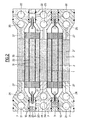
- FIG. 1 shows two pairs of elementary generators consisting respectively of the flat electrodes 1, 2 and 1 ′, 2 ′ extending in the direction of the width of the stack, the polarities of which are inverted so that the electrodes 2 and 2 1 contiguous, included between the external electrodes 1 and 1 ', are of the same polarity and are joined along their long sides to form extensions 16 common planes, one of which extends in height in the rectangular frame base 3 formed of two symmetrical parts joined and which tighten this extension.
- the external electrodes 1 and 1 ′ come together but only at one end to form an extension 17, which overlaps at this end the volume in the form of an elongated bag formed by all of the electrodes 2, 2 'and which is clamped between the two parts of the frame 3, on the side opposite to that in which extends the common extension 16 of the electrodes 2, 2'.
- the batteries are mounted head to tail, that is to say that on the same side lead alternately to the extensions 16 or 17 of the electrodes 2, 2 'or 1, 1', a rectangular frame such as 7 being arranged between each sub-assembly or basic generator, this intermediate frame serving on the one hand to delimit chambers such as 35 between two sub-assemblies and to receive supply channels 11, 12, 13 and outlet for the electrolyte and reagents.
- Electrodes 1, 1 ', 2, 2' are arranged on the entire width of the stack of elastic spacers 8, which maintain the appropriate spacings between respectively the flat electrodes 1 and 2, 2 and 2 ', 2 and 1', these spacers, formed of separate flat elements, allowing by suitable channels 9 the circulation of fluids.
- the spaces delimited between the electrodes thus form successive chambers 32, in the space between electrodes 2 and 2 ', which divides the chamber 31 into two parts joined on one side by the chamber 33 beyond a spacer 8 and by passages 17 provided in the extension 16 of the electrodes 1, 1 ′, finally chambers 35 included between the electrodes 1-1 of the two associated sub-assemblies and the internal sides of the intermediate frames.
- Conduits 14 or 15 put the end chambers 33 in communication with the channels 11 or 12. The electrolyte then flows through the spacers 8 through openings 9.
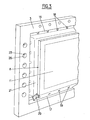
- FIG. 2 which shows a cross section along II-II of the basic generator of FIG. 1, it can be seen that channels 21-22 pierced longitudinally in the lateral uprights of the intermediate frames 7 supply a first reagent by conduits 20, cells 26 into each of which opens a small supply tube 23 which fits tightly between the closed lips of the electrodes 2-2 '.
- longitudinal inlet 24 and outlet 25 channels parallel to the channels 21 circulate a second reagent in the spaces 35 by means of conduits 27.
- seals 10 and 29 Sealing is ensured between frames 3 and 7 by means of seals 10 and 29; the joints can be an extension of the joints 10 in the other direction, at the cost of the separations required by an appropriate joint bar.
- FIG. 3 represents a partial perspective view of the basic generator and FIGS. 4 and 5 two partial views.
- This comprises two interior electrodes 2 and 2 ′ and two exterior electrodes 1 and 1 ′ which form a bridging lining for them, trapping the spacers 6 and spacers 8 already described.
- the electrodes are in particular made up as is often the case of a skeleton of metallic and conductive electrode allowing the collection of the current formed, which conductive and porous support being coated or coated with the aggregate of catalyst, activated carbon, teflon, in order to allow the formation of capillaries where meet reactive products, catalyst and electrolyte.
- the spacer 8 is presented as a frame of elastic and waterproof material comprising semicircular grooves 9 constituting the reserved passages electrolyte or reagents. Inside the frame is located a lattice of crossed rods 36 having at the crossing nodes heads 37 having the same thickness as the frame and which thus maintain the appropriate spacing between the electrodes.
- the composite part comprising all of the interlayer 6 and the spacer 8 can in particular be produced by butyl pressure molding.
- the electrodes 2 and 2 ', forming the closed volume leaving passage only to the serving tube 18 of reactive product, can as we have seen be joined by gluing or welding. In the case of bonding, certain points must be welded to ensure electrical paralleling and the flow of current formed by the electrodes.
- the usual electrolyte will generally be potassium hydroxide, while the reactants will generally be on one side the air, which will preferably be introduced into the chambers, and on the other of the hydrogen introduced into the chambers. 32. This will give a positive polarity on the outside electrodes 1 and negative on the inside electrodes 2.
- reagents could be used, for example oxygen or chlorine in place of air, methanole, various hydrocarbons or ammonium NH 4 in place of hydrogen.
- the catalysts generally used are, on the oxygen or air side, silver, iron phthalocyanine, activated carbon, hydrogen side nickel, 1 Raney Nickel, optionally doped with titanium or platinum.
Landscapes
- Life Sciences & Earth Sciences (AREA)
- Engineering & Computer Science (AREA)
- Manufacturing & Machinery (AREA)
- Sustainable Development (AREA)
- Sustainable Energy (AREA)
- Chemical & Material Sciences (AREA)
- Chemical Kinetics & Catalysis (AREA)
- Electrochemistry (AREA)
- General Chemical & Material Sciences (AREA)
- Fuel Cell (AREA)
Applications Claiming Priority (2)
| Application Number | Priority Date | Filing Date | Title |
|---|---|---|---|
| FR8106116 | 1981-03-26 | ||
| FR8106116A FR2502850A1 (fr) | 1981-03-26 | 1981-03-26 | Perfectionnement aux piles a combustible |
Publications (1)
| Publication Number | Publication Date |
|---|---|
| EP0061942A1 true EP0061942A1 (fr) | 1982-10-06 |
Family
ID=9256681
Family Applications (1)
| Application Number | Title | Priority Date | Filing Date |
|---|---|---|---|
| EP82400271A Withdrawn EP0061942A1 (fr) | 1981-03-26 | 1982-02-16 | Perfectionnement aux piles à combustible |
Country Status (3)
| Country | Link |
|---|---|
| EP (1) | EP0061942A1 (enExample) |
| ES (1) | ES8303829A1 (enExample) |
| FR (1) | FR2502850A1 (enExample) |
Cited By (3)
| Publication number | Priority date | Publication date | Assignee | Title |
|---|---|---|---|---|
| FR2579025A1 (fr) * | 1985-03-15 | 1986-09-19 | Occidental Chem Co | Pile a combustible a separation amelioree |
| EP0327528A3 (de) * | 1988-02-01 | 1990-06-13 | Elin Energieanwendung Gesellschaft M.B.H. | Metall/Halogen-Batterie |
| US6080883A (en) * | 1997-04-04 | 2000-06-27 | Basf Aktiengesellschaft | Method of simultaneously producing 6-aminocapronitrile and hexamethylenediamine |
Citations (3)
| Publication number | Priority date | Publication date | Assignee | Title |
|---|---|---|---|---|
| US3589941A (en) * | 1969-02-24 | 1971-06-29 | Onan Corp | Fuel cell with internal manifolds |
| FR2169758A1 (enExample) * | 1972-01-31 | 1973-09-14 | Inst Francais Du Petrole | |
| GB2006101A (en) * | 1977-10-14 | 1979-05-02 | Electrochem Energieconversie | An electrochemical cell or battery |
-
1981
- 1981-03-26 FR FR8106116A patent/FR2502850A1/fr active Granted
-
1982
- 1982-02-16 EP EP82400271A patent/EP0061942A1/fr not_active Withdrawn
- 1982-03-25 ES ES510783A patent/ES8303829A1/es not_active Expired
Patent Citations (3)
| Publication number | Priority date | Publication date | Assignee | Title |
|---|---|---|---|---|
| US3589941A (en) * | 1969-02-24 | 1971-06-29 | Onan Corp | Fuel cell with internal manifolds |
| FR2169758A1 (enExample) * | 1972-01-31 | 1973-09-14 | Inst Francais Du Petrole | |
| GB2006101A (en) * | 1977-10-14 | 1979-05-02 | Electrochem Energieconversie | An electrochemical cell or battery |
Cited By (6)
| Publication number | Priority date | Publication date | Assignee | Title |
|---|---|---|---|---|
| FR2579025A1 (fr) * | 1985-03-15 | 1986-09-19 | Occidental Chem Co | Pile a combustible a separation amelioree |
| WO1986005629A1 (fr) * | 1985-03-15 | 1986-09-25 | Occidental Chemical Corporation | Pile a combustible a separation amelioree |
| EP0199611A1 (fr) * | 1985-03-15 | 1986-10-29 | Occidental Chemical Corporation | Pile à combustible à élément de séparation |
| US4758481A (en) * | 1985-03-15 | 1988-07-19 | Occidental Chemical Corporation | Fuel cell with improved separation |
| EP0327528A3 (de) * | 1988-02-01 | 1990-06-13 | Elin Energieanwendung Gesellschaft M.B.H. | Metall/Halogen-Batterie |
| US6080883A (en) * | 1997-04-04 | 2000-06-27 | Basf Aktiengesellschaft | Method of simultaneously producing 6-aminocapronitrile and hexamethylenediamine |
Also Published As
| Publication number | Publication date |
|---|---|
| FR2502850B1 (enExample) | 1983-05-20 |
| ES510783A0 (es) | 1983-02-01 |
| ES8303829A1 (es) | 1983-02-01 |
| FR2502850A1 (fr) | 1982-10-01 |
Similar Documents
| Publication | Publication Date | Title |
|---|---|---|
| FR2568412A1 (fr) | Perfectionnements aux structures des piles a combustible. | |
| CA1277368C (fr) | Amenagements aux structures des piles a combustibles | |
| FR2582155A1 (fr) | Cellule electrochimique composee d'elements electrochimiques a oxyde solide et a coeur monolithique raccordes en serie, et element constitutif d'une telle cellule | |
| CA1287100C (fr) | Pile a combustible a separation amelioree | |
| FR2553582A1 (fr) | Pile a combustible a oxyde solide comportant un noyau a ecoulement transversal et un systeme de distribution | |
| CA2182069C (en) | Modular ceramic oxygen generator | |
| FR2491957A1 (fr) | Ensemble de cellules electrochimiques et procede pour y reduire le courant de fuite | |
| EP0202981A1 (fr) | Dispositif d'échange thermique utilisable notamment pour des échanges entre gaz | |
| CA1277366C (fr) | Perfectionnements aux structures des piles a combustible | |
| CA1277367C (fr) | Ameliorations aux structures des piles a combustible | |
| FR2846799A1 (fr) | Module pour un systeme de cellules electrochimiques | |
| EP2021720B1 (fr) | Echangeur de chaleur a plaques d'echange soudees | |
| EP0061942A1 (fr) | Perfectionnement aux piles à combustible | |
| FR2861896A1 (fr) | Structure pour pile a combustible | |
| EP0114667A2 (fr) | Générateur électrochimique de type bouton | |
| EP1846976B1 (fr) | Convertisseur electrochimique compact | |
| FR2700639A1 (fr) | Batterie d'accumulateurs électriques équipée de moyens d'étanchement perfectionnés. | |
| FR2499774A1 (fr) | Bloc de pile a combustible constitue d'un empilement d'elements creux portant des electrodes | |
| FR3040397A1 (fr) | Generateur d’hydrogene par electrolyse de l’eau | |
| EP0599714A1 (fr) | Echangeur massique et thermique à plaques poreuses | |
| FR2870388A1 (fr) | Cellule de pile a combustible a electrolyte solide | |
| FR2503621A1 (fr) | Poche en matiere plastique a peripherie soudee destinee a etre compartimentee | |
| EP4342018A1 (fr) | Elément électrochimique pour batterie, et batterie correspondante | |
| FR2851080A1 (fr) | Batterie comportant plusieurs cellules et procede pour connecter les cellules d'une telle batterie | |
| FR2866699A1 (fr) | Echangeur thermique a plaques nervurees soudees |
Legal Events
| Date | Code | Title | Description |
|---|---|---|---|
| PUAI | Public reference made under article 153(3) epc to a published international application that has entered the european phase |
Free format text: ORIGINAL CODE: 0009012 |
|
| 17P | Request for examination filed |
Effective date: 19820219 |
|
| AK | Designated contracting states |
Designated state(s): AT BE CH DE GB IT NL SE |
|
| STAA | Information on the status of an ep patent application or granted ep patent |
Free format text: STATUS: THE APPLICATION IS DEEMED TO BE WITHDRAWN |
|
| 18D | Application deemed to be withdrawn |
Effective date: 19840901 |
|
| RIN1 | Information on inventor provided before grant (corrected) |
Inventor name: BRETING, OLIVIER Inventor name: BOUTHORS, PIERRE |