EP0061942A1 - Fuel cells - Google Patents
Fuel cells Download PDFInfo
- Publication number
- EP0061942A1 EP0061942A1 EP82400271A EP82400271A EP0061942A1 EP 0061942 A1 EP0061942 A1 EP 0061942A1 EP 82400271 A EP82400271 A EP 82400271A EP 82400271 A EP82400271 A EP 82400271A EP 0061942 A1 EP0061942 A1 EP 0061942A1
- Authority
- EP
- European Patent Office
- Prior art keywords
- electrodes
- fuel cell
- electrolyte
- cell according
- frame
- Prior art date
- Legal status (The legal status is an assumption and is not a legal conclusion. Google has not performed a legal analysis and makes no representation as to the accuracy of the status listed.)
- Withdrawn
Links
Images


Classifications
-
- H—ELECTRICITY
- H01—ELECTRIC ELEMENTS
- H01M—PROCESSES OR MEANS, e.g. BATTERIES, FOR THE DIRECT CONVERSION OF CHEMICAL ENERGY INTO ELECTRICAL ENERGY
- H01M8/00—Fuel cells; Manufacture thereof
- H01M8/24—Grouping of fuel cells, e.g. stacking of fuel cells
- H01M8/2459—Comprising electrode layers with interposed electrolyte compartment with possible electrolyte supply or circulation
-
- H—ELECTRICITY
- H01—ELECTRIC ELEMENTS
- H01M—PROCESSES OR MEANS, e.g. BATTERIES, FOR THE DIRECT CONVERSION OF CHEMICAL ENERGY INTO ELECTRICAL ENERGY
- H01M8/00—Fuel cells; Manufacture thereof
- H01M8/02—Details
- H01M8/0271—Sealing or supporting means around electrodes, matrices or membranes
- H01M8/0273—Sealing or supporting means around electrodes, matrices or membranes with sealing or supporting means in the form of a frame
-
- Y—GENERAL TAGGING OF NEW TECHNOLOGICAL DEVELOPMENTS; GENERAL TAGGING OF CROSS-SECTIONAL TECHNOLOGIES SPANNING OVER SEVERAL SECTIONS OF THE IPC; TECHNICAL SUBJECTS COVERED BY FORMER USPC CROSS-REFERENCE ART COLLECTIONS [XRACs] AND DIGESTS
- Y02—TECHNOLOGIES OR APPLICATIONS FOR MITIGATION OR ADAPTATION AGAINST CLIMATE CHANGE
- Y02E—REDUCTION OF GREENHOUSE GAS [GHG] EMISSIONS, RELATED TO ENERGY GENERATION, TRANSMISSION OR DISTRIBUTION
- Y02E60/00—Enabling technologies; Technologies with a potential or indirect contribution to GHG emissions mitigation
- Y02E60/30—Hydrogen technology
- Y02E60/50—Fuel cells
Definitions
- the present invention relates in particular to fuel cells consisting of a plurality of basic electrical generator elements, each of them being itself the parallel association of two elementary generators.
- fuel cells usually comprise, for each of their elementary generators, two volumes containing respectively fuel and oxidizer, which are separated by a third volume filled with electrolyte.
- the flat and porous membranes separating fuel and electrolyte, or oxidizer and electrolyte, are the electrodes which contain suitable catalysts, at the same time as they transmit the currents formed by the cell.
- these electrodes to fulfill these roles, comprise a conductive and porous skeleton into which the catalyst is inserted, the assembly having a network of capillaries in which are present: fuel or oxidizer, specific catalyst and electrolyte. This results in ionizations associated with absorption or release of electrons depending on whether the electrode is + or -. And the transfer of these electrons, under the polarization reached, forms the useful external current of the battery.
- the battery according to the present invention is of the last kind where the polarities of the basic elements are alternated every other time, and the basic generator of which is established in accordance with the so-called filter press technique.
- This basic generator is characterized by the fact that, comprising two elementary generators each having two electrodes spaced apart by a volume containing an electrolyte, two contiguous electrodes each belonging to a different elementary generator being electrically connected in parallel, and the two other electrodes located apart and other of the first aforementioned electrodes being also connected in parallel, this generator is secured by the same frame which receives on two sides opposite the parallel connections of electrodes, and on the other two the service conduits of the reagent supplying the closed central volume formed by their appropriate meeting the two electrodes located side by side and belonging respectively to one and to the other of the two generators.
- the subassemblies which form the basic generators and which group two elementary stacks or generators connected in parallel are separated by intermediate frames whose role is to ensure all the fluid supplies required by the stack , that is to say electrolyte and reagents, at the same time that it delivers passage and supports the necessary electrical connections.
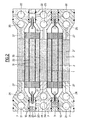
- FIG. 1 shows two pairs of elementary generators consisting respectively of the flat electrodes 1, 2 and 1 ′, 2 ′ extending in the direction of the width of the stack, the polarities of which are inverted so that the electrodes 2 and 2 1 contiguous, included between the external electrodes 1 and 1 ', are of the same polarity and are joined along their long sides to form extensions 16 common planes, one of which extends in height in the rectangular frame base 3 formed of two symmetrical parts joined and which tighten this extension.
- the external electrodes 1 and 1 ′ come together but only at one end to form an extension 17, which overlaps at this end the volume in the form of an elongated bag formed by all of the electrodes 2, 2 'and which is clamped between the two parts of the frame 3, on the side opposite to that in which extends the common extension 16 of the electrodes 2, 2'.
- the batteries are mounted head to tail, that is to say that on the same side lead alternately to the extensions 16 or 17 of the electrodes 2, 2 'or 1, 1', a rectangular frame such as 7 being arranged between each sub-assembly or basic generator, this intermediate frame serving on the one hand to delimit chambers such as 35 between two sub-assemblies and to receive supply channels 11, 12, 13 and outlet for the electrolyte and reagents.
- Electrodes 1, 1 ', 2, 2' are arranged on the entire width of the stack of elastic spacers 8, which maintain the appropriate spacings between respectively the flat electrodes 1 and 2, 2 and 2 ', 2 and 1', these spacers, formed of separate flat elements, allowing by suitable channels 9 the circulation of fluids.
- the spaces delimited between the electrodes thus form successive chambers 32, in the space between electrodes 2 and 2 ', which divides the chamber 31 into two parts joined on one side by the chamber 33 beyond a spacer 8 and by passages 17 provided in the extension 16 of the electrodes 1, 1 ′, finally chambers 35 included between the electrodes 1-1 of the two associated sub-assemblies and the internal sides of the intermediate frames.
- Conduits 14 or 15 put the end chambers 33 in communication with the channels 11 or 12. The electrolyte then flows through the spacers 8 through openings 9.
- FIG. 2 which shows a cross section along II-II of the basic generator of FIG. 1, it can be seen that channels 21-22 pierced longitudinally in the lateral uprights of the intermediate frames 7 supply a first reagent by conduits 20, cells 26 into each of which opens a small supply tube 23 which fits tightly between the closed lips of the electrodes 2-2 '.
- longitudinal inlet 24 and outlet 25 channels parallel to the channels 21 circulate a second reagent in the spaces 35 by means of conduits 27.
- seals 10 and 29 Sealing is ensured between frames 3 and 7 by means of seals 10 and 29; the joints can be an extension of the joints 10 in the other direction, at the cost of the separations required by an appropriate joint bar.
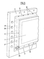
- FIG. 3 represents a partial perspective view of the basic generator and FIGS. 4 and 5 two partial views.
- This comprises two interior electrodes 2 and 2 ′ and two exterior electrodes 1 and 1 ′ which form a bridging lining for them, trapping the spacers 6 and spacers 8 already described.
- the electrodes are in particular made up as is often the case of a skeleton of metallic and conductive electrode allowing the collection of the current formed, which conductive and porous support being coated or coated with the aggregate of catalyst, activated carbon, teflon, in order to allow the formation of capillaries where meet reactive products, catalyst and electrolyte.
- the spacer 8 is presented as a frame of elastic and waterproof material comprising semicircular grooves 9 constituting the reserved passages electrolyte or reagents. Inside the frame is located a lattice of crossed rods 36 having at the crossing nodes heads 37 having the same thickness as the frame and which thus maintain the appropriate spacing between the electrodes.
- the composite part comprising all of the interlayer 6 and the spacer 8 can in particular be produced by butyl pressure molding.
- the electrodes 2 and 2 ', forming the closed volume leaving passage only to the serving tube 18 of reactive product, can as we have seen be joined by gluing or welding. In the case of bonding, certain points must be welded to ensure electrical paralleling and the flow of current formed by the electrodes.
- the usual electrolyte will generally be potassium hydroxide, while the reactants will generally be on one side the air, which will preferably be introduced into the chambers, and on the other of the hydrogen introduced into the chambers. 32. This will give a positive polarity on the outside electrodes 1 and negative on the inside electrodes 2.
- reagents could be used, for example oxygen or chlorine in place of air, methanole, various hydrocarbons or ammonium NH 4 in place of hydrogen.
- the catalysts generally used are, on the oxygen or air side, silver, iron phthalocyanine, activated carbon, hydrogen side nickel, 1 Raney Nickel, optionally doped with titanium or platinum.
Abstract
Description
La présente invention se rapporte notamment aux piles à combustible constituées d'une pluralité d'éléments générateurs électriques de base, chacun d'eux étant lui-mêmé l'association parallèle'de deux générateurs élémentaires.The present invention relates in particular to fuel cells consisting of a plurality of basic electrical generator elements, each of them being itself the parallel association of two elementary generators.
On sait pour mémoire que les piles à combustible comportent habituellement, pour chacun de leurs générateurs élémentaires, deux volumes contenant respectivement combustible et comburant, lesquels sont séparés par un troisième volume rempli d'électrolyte. Les membranes planes et poreuses séparant combustible et électrolyte, ou comburant et électrolyte, sont les électrodes qui contiennent des catalyseurs appropriés, en même temps qu'elles transmettent les courants formés par la pile.It is known for the record that fuel cells usually comprise, for each of their elementary generators, two volumes containing respectively fuel and oxidizer, which are separated by a third volume filled with electrolyte. The flat and porous membranes separating fuel and electrolyte, or oxidizer and electrolyte, are the electrodes which contain suitable catalysts, at the same time as they transmit the currents formed by the cell.
Le plus souvent ces électrodes, pour remplir ces rôles, comprennent un squelette conducteur et poreux dans lequel est inséré le catalyseur, l'ensemble présentant un réseau de capillaires où se trouvent en présence : combustible ou comburant, catalyseur spécifique et électrolyte. Il en résulte des ionisations associées à des absorptions ou libérations d'électrons selon que l'électrode est + ou -. Et le transfert de ces électrons, sous la polarisation atteinte, forme le courant extérieur utile de la pile.Most often these electrodes, to fulfill these roles, comprise a conductive and porous skeleton into which the catalyst is inserted, the assembly having a network of capillaries in which are present: fuel or oxidizer, specific catalyst and electrolyte. This results in ionizations associated with absorption or release of electrons depending on whether the electrode is + or -. And the transfer of these electrons, under the polarization reached, forms the useful external current of the battery.
Il est clair que si on associe en série, une sucoes- sion de tels éléments dont les polarités sont disposées identiquement, deux éléments consécutifs se jouxteront par les compartiments contenant l'un du combustible, l'autre du comburant, et ces deux compartiments devront être séparés par une cloison étanche. Tout au contraire, si on alterne une fois sur deux l'ordre des polarités, on sait que les mêmes compartiments de combustible ou de comburant pourront baigner les électrodes en vis-à-vis des deux éléments de'pile successifs.It is clear that if we combine in series, a succession of such elements whose polarities are identically arranged, two consecutive elements will abut by the compartments containing one of the fuel, the other of the oxidizer, and these two compartments must be separated by a bulkhead. On the contrary, if we alternate the order of polarities once in two, we know that the same fuel or oxidizer compartments can bathe the electrodes opposite the two successive battery cells.
La pile conforme à la présente invention est de la dernière sorte où les polarités des éléments de base sont alternées une fois sur deux, et dont le générateur de base est établi conformément à la technique dite du filtre presse. Ce générateur de base est caractérisé par ceci que, comprenant deux générateurs élémentaires ayant chacun deux électrodes espacées par un volume contenant un électrolyte, deux électrodes contiguës appartenant chacune à un générateur élémentaire différent étant reliées électriquement en parallèle, et les deux autres électrodes situées de part et d'autre des premières électrodes précitées étant également reliées en parallèle, ce générateur est solidarisé par un même cadre qui reçoit sur deux côtes en vis-à-vis les branchements parallèles d'électrodes, et sur les deux autres les conduits de desserte du réactif alimentant le volume central fermé que forment par leur réunion appropriée les deux électrodes situées côte à c8te et appartenant respectivement à l'un et à l'autre des deux générateurs. Ce volume compris entre deux électrodes contiguës et raccordées, ayant donc mëme signe, n'ouvre passage qu'aux canaux spécialisés qui en desservent l'entrée et la sortie, cette sortie comprenant, éventuellement, des canaux d'assèchement pour compenser le "perlage" de l'électrolyte dans ce volume.The battery according to the present invention is of the last kind where the polarities of the basic elements are alternated every other time, and the basic generator of which is established in accordance with the so-called filter press technique. This basic generator is characterized by the fact that, comprising two elementary generators each having two electrodes spaced apart by a volume containing an electrolyte, two contiguous electrodes each belonging to a different elementary generator being electrically connected in parallel, and the two other electrodes located apart and other of the first aforementioned electrodes being also connected in parallel, this generator is secured by the same frame which receives on two sides opposite the parallel connections of electrodes, and on the other two the service conduits of the reagent supplying the closed central volume formed by their appropriate meeting the two electrodes located side by side and belonging respectively to one and to the other of the two generators. This volume comprised between two contiguous and connected electrodes, therefore having the same sign, only opens passage to specialized channels which serve the input and the output thereof, this output comprising, possibly, draining channels to compensate for the "beading "of the electrolyte in this volume.
Dans la pile complète, les sous-ensembles que forment les générateurs de base et qui groupent deux piles ou générateurs élémentaires connectés en parallèle sont séparés par des cadres intercalaires dont le rôle est d'assurer l'ensemble des dessertes en fluide requis par la pile, c'est-à-dire électrolyte et réactifs, en même temps qu'il livre passage et supporte les connexions électriques nécessaires.In the complete stack, the subassemblies which form the basic generators and which group two elementary stacks or generators connected in parallel are separated by intermediate frames whose role is to ensure all the fluid supplies required by the stack , that is to say electrolyte and reagents, at the same time that it delivers passage and supports the necessary electrical connections.
L'invention sera maintenant décrite en se référant à titre d'exemple à une forme de réalisation représentée au dessin annexé dans lequel :
- - la figure 1 représente une coupe schématique en élévation de la pile, formée de deux générateurs de base, montrant la disposition des électrodes et des cadres ;
- - la figure 2 représente la coupe transversale de la même pile selon un plan II-II de la figure 1 perpendiculaire au précédent selon une disposition non limitative des alimentations de la pile en fluides divers ;
- - la figure 3 représente une vue schématique, en perspective d'un sous-ensemble formant générateur de base de la pile dans ces mêmes conditions ;
- - la figure 4 est une vue de détail d'une partie d'un élément entretoise-intercalaire ;
- - la figure 5 est une coupe partielle suivant V-V de la figure 4.
- - Figure 1 shows a schematic sectional elevation of the battery, formed of two base generators, showing the arrangement of the electrodes and frames;
- - Figure 2 shows the cross section of the same stack along a plane II-II of Figure 1 perpendicular to the previous one according to a nonlimiting arrangement of the supplies of the stack with various fluids;
- - Figure 3 shows a schematic perspective view of a sub-assembly forming the base generator of the battery under these same conditions;
- - Figure 4 is a detail view of part of a spacer-spacer element;
- - Figure 5 is a partial section along VV of Figure 4.
On a représenté à la figure 1 deux paires de générateurs élémentaires constitués respectivement des électrodes planes 1, 2 et 1', 2' s'étendant dans le sens de la largeur de la pile, dont les polarités sont inverties de telle sorte que les électrodes 2 et 21 contiguës, comprises entre les électrodes extérieures 1 et 1', sont de même polarité et sont réunies le long de leurs grands côtés pour former des prolongements 16 communs plans, dont l'un s'étend en hauteur dans le cadre rectangulaire de base 3 formé de deux parties symétriques accolées et qui serrent ce prolongement.FIG. 1 shows two pairs of elementary generators consisting respectively of the
D'une façon analogue, les électrodes extérieures 1 et 1', également de même polarité, se rapprochent mais a une extrémité seulement pour former un prolongement 17, qui chevauche à cette extrémité le volume en forme de sac allongé constitué par l'ensemble des électrodes 2, 2' et qui est serré entre les deux parties du cadre 3, du côté opposé à celui dans lequel s'étend le prolongement commun 16 des électrodes 2, 2'.In an analogous manner, the
Comme représenté, pour former l'ensemble, les piles sont montées tête-bêche, c'est-à-dire que d'un même côté aboutissent alternativement les prolongements 16 ou 17 des électrodes 2, 2' ou 1, 1', un cadre rectangulaire tel que 7 étant disposé entre chaque sous-ensemble ou générateur de base, ce cadre intercalaire servant d'une part à délimiter des chambres telles que 35 entre deux sous-ensembles et à recevoir des canaux 11, 12, 13 d'alimentation et de sortie pour l'électrolyte et les réactifs.As shown, to form the assembly, the batteries are mounted head to tail, that is to say that on the same side lead alternately to the
Entre les électrodes 1, 1', 2, 2' sont disposées sur toute la largeur de la pile des entretoises élastiques 8, qui maintiennent les écartements convenables entre respectivement les électrodes planes 1 et 2, 2 et 2' , 2 et 1', ces entretoises, formées d'éléments séparés plans, permettant par des canaux convenables 9 la circulation des fluides. Les espaces délimités entre les électrodes forment ainsi des chambres successives 32, dans l'espace compris entre les électrodes 2 et 2', qui divise la chambre 31 en deux parties réunies d'un côté par la chambre 33 au-delà d'une entretoise 8 et par des passages 17 prévus dans le prolongement 16 des électrodes 1, 1', enfin des chambres 35 comprises entre les électrodes 1-1 des deux sous-ensembles associés et les côtés internes des cadres intercalaires.Between the
Les différentes chambres 31, 32, 33 et 35, dans lesquelles sont disposés des intercalaires 6, sont respectivement alimentées en réactifs, comburant et combustible, et en électrolyte de la façon qui sera décrite ci-après :
- L'électrolyte destiné à imprégner l'espace inter-
électrodes 31 arrive par des canaux longitudinaux percés horizontalement à travers les cadres intercalaires 7, respectivement d'arrivée et deretour 11 et 12, l'arrivée s'effectuant de préférence par le bas pour éviter la formation de bulles néfastes au bon fonctionnement des circuits.
- The electrolyte intended to impregnate the
inter-electrode space 31 arrives by longitudinal channels pierced horizontally through theintermediate frames 7, respectively of arrival and return 11 and 12, the arrival preferably taking place from below for avoid the formation of bubbles harmful to the proper functioning of the circuits.
Des conduits 14 ou 15 mettent en communication les chambres d'extrémités 33 avec les canaux 11 ou 12. L'électrolyte circule ensuite à travers les entretoises 8 par des ouvertures 9.
Les canaux d'électrolyte, d'entrée 11 et de sortie 12, servent par leur longueur et leur résistance ohmique à éviter les courts-circuits excessifs entre électrodes de tension différentes. Aussi pour augmenter les longueurs de canalisations entre points de tensions différentes, est-il bon de réaliser des circuits en forme de grecque en réunissant les canalisations de deux cadres 7 successifs par des canaux 13 traversant, perpendiculairement à ces canaux 11 ou 12, les cadres 7 et les cadres 3 à l'une puis l'autre des extrémités des canaux 11 ou
- 12. Dans un tel cas il peut être préférable de ne desservir un générateur de base à deux paires d'électrodes que par une seule nappe de tuyères comme 14 ou 15, venant d'un
même canal 11 ou - 12. Ainsi, comme l'une des nappes dessert l'électrolyte d'un seul côté d'un branchement parallèle des électrodes intérieures il faut que, après, leur connexion, ces électrodes présentent des
orifices 18. De meme, près de leur réunion, les électrodes extérieures du générateur de base doivent être percées d'orifices comme 19.
- 12. In such a case it may be preferable to serve a basic generator with two pairs of electrodes only by a single ply of nozzles such as 14 or 15, coming from the
same channel 11 or - 12. Thus, as one of the layers serves the electrolyte on only one side of a parallel connection of the interior electrodes, it is necessary that, after their connection, these electrodes have
orifices 18. Similarly, close to their meeting , the external electrodes of the basic generator must be pierced with holes like 19.
En se reportant à la figure 2, qui montre une coupe transversale selon II-II du générateur de base de la figure 1, on voit que des canaux 21-22 percés longitudinalement dans les montants latéraux des cadres intercalaires 7 alimentent en un premier réactif par des conduits 20, des alvéoles 26 dans chacune desquelles débouche un petit tube d'alimentation 23 qui s'insère de façon étanche entre les lèvres refermées des électrodes 2-2'. De mëme, des canaux longitudinaux d'entrée 24 et de sortie 25 parallèles aux canaux 21 font circuler un second réactif dans les espaces 35 au moyen de conduits 27.Referring to FIG. 2, which shows a cross section along II-II of the basic generator of FIG. 1, it can be seen that channels 21-22 pierced longitudinally in the lateral uprights of the
L'étanchéité est assurée entre les cadres 3 et 7 au moyen de joints 10 et 29 ; les joints peuvent ëtre le prolongement des joints 10 de l'autre direction, au prix des séparations requises par barrette de joint appropriée.Sealing is ensured between
Les conditions de réalisation matérielle apparaîtront mieux à la faveur de la figure 3 qui représente une vue partielle en perspective du générateur de base et les figures 4 et 5 deux vues partielles. Celui-ci comprend deux électrodes intérieures 2 et 2' et deux électrodes extérieures 1 et 1' qui leur forment une doublure cavalière en emprisonnant les intercalaires 6 et entretoises 8 déjà décrits. Les électrodes sont notamment constituées comme souvent c'est le cas d'un squelette d'électrode métallique et conducteur permettant la collecte du courant formé, lequel support conducteur et poreux étant enduit ou revêtu de l'agrégat de catalyseur, de charbon actif, de téflon, en vue de permettre la formation de capillaires où se rencontrent produits réactifs, catalyseur et électrolyte. Les parties non planes des électrodes, difficiles à traiter de cette sorte gagnent habituellement à rester sans ces produits, il suffit de rendre étanche à ces endroits le support poreux par une enduction de mastic étanche, le mastic à base de butyl en est un exemple courant. Il faut aussi noter que, avant tout traitement, les squelettes d'électrodes 2 et 2' ont été mis en forme pour recevoir les tubes qui assureront dans le sac qu'elles forment la circulation en produit réactifo Le volume fermé qu'elles forment après réunion étanche contient, parce qu'il a été posé avant réunion, un intercalaire 6 directement relié aux entretoises 8.The conditions of material production will appear better in favor of FIG. 3 which represents a partial perspective view of the basic generator and FIGS. 4 and 5 two partial views. This comprises two
Pour mieux faire comprendre la réalisation des entretoises 8 et des intercalaires 6, un exemple a été représenté aux figures 4 et 5. L'entretoise 8 se présente comme un cadre de matière élastique et étanche comportant des gorges semi- circulaires 9 constituant les passages réservés à l'électrolyte ou aux réactifs. A l'intérieur du cadre est situé un treillis de tiges croisillonnées 36 présentant aux noeuds de croisement des têtes 37 ayant même épaisseur que le cadre et qui maintiennent ainsi l'écartement convenable entre les électrodes.To better understand the embodiment of the
Dans un générateur de base, trois telles entretoises- intercalées 81, 82, 83 sont ainsi disposées parallèlement dans les intervalles entre les électrodes.In a basic generator, three such interposed
La pièce composite comprenant l'ensemble de l'intercalaire 6 et de l'entretoise 8 peut notamment être réalisée par moulage sous pression en butyl. Les électrodes 2 et 2', formant le volume fermé ne laissant passage qu'au tube de desserte 18 de produit réactif, peuvent comme on a vu être réunies par collage ou soudure. Dans le cas du collage, il faut que certains points soient soudés pour assurer la mise en parallèle électrique et l'écoulement du courant formé par les électrodes. En regard des points où se réalise le branchement électrique d'une électrode à la suivante par les conducteurs 4, il peut être prévu au fond du perçage une pastille 5 soudée ou brasée qui protège l'électrode.The composite part comprising all of the interlayer 6 and the
On reconnaît les trous 19 forés dans les électrodes 1, 1' pour permettre le bon écoulement de l'électrolyte. De même, on voit un des bouchons de mastic 29 qui empêchent à chaque angle de préférence, mais nécessairement à deux d'entre eux, hauts ou bas, que l'électrolyte ne soit conduit directement de l'entrée à la sortie en passant pour ce faire par le côté extérieur des électrodes 1, 1', c'est-à-dire par l'ensemble des chambres communicantes 33 constituant un by-pass entre les conduits d'entrée et de sortie. Une partie doit en être placée au montage des cadres 7 et de l'ensemble, entre électrodes extérieures 1, l' et cadre 7.We recognize the
Pour le fonctionnement, l'électrolyte usuel sera généralement la potasse, alors que les réactifs seront généralement d'un côté l'air, qui sera introduit de préférence dans les chambres 35, et de l'autre de l'hydrogène introduit dans les chambres 32. On obtiendra ainsi une polarité positive sur les électrodes extérieures 1 et négative sur les électrodes intérieure 2.For operation, the usual electrolyte will generally be potassium hydroxide, while the reactants will generally be on one side the air, which will preferably be introduced into the chambers, and on the other of the hydrogen introduced into the chambers. 32. This will give a positive polarity on the
D'autres réactifs pourraient ëtre utilisés, par exemple l'oxygène ou le chlore à la place de l'air, le méthanole, divers hydrocarbures ou l'ammonium NH4 à la place de l'hydrogène. Les catalyseurs généralement utilises sont, du côté oxygène ou air, l'argent,la phtalocyanine de fer, le charbon actif, coté hydrogène le nickel, 1 Raney Nickel, éventuellement dopés au titane ou le platine.Other reagents could be used, for example oxygen or chlorine in place of air, methanole, various hydrocarbons or ammonium NH 4 in place of hydrogen. The catalysts generally used are, on the oxygen or air side, silver, iron phthalocyanine, activated carbon, hydrogen side nickel, 1 Raney Nickel, optionally doped with titanium or platinum.
En fonctionnement, il est avantageux d'assurer une pression prépondérante à l'électrolyte, de manière à éviter le "bullage" au passage d'un réactif dans l'électrolyte.In operation, it is advantageous to ensure a preponderant pressure for the electrolyte, so as to avoid "bubbling" when a reagent passes through the electrolyte.
Claims (15)
Applications Claiming Priority (2)
| Application Number | Priority Date | Filing Date | Title |
|---|---|---|---|
| FR8106116 | 1981-03-26 | ||
| FR8106116A FR2502850A1 (en) | 1981-03-26 | 1981-03-26 | FUEL CELL IMPROVEMENT |
Publications (1)
| Publication Number | Publication Date |
|---|---|
| EP0061942A1 true EP0061942A1 (en) | 1982-10-06 |
Family
ID=9256681
Family Applications (1)
| Application Number | Title | Priority Date | Filing Date |
|---|---|---|---|
| EP82400271A Withdrawn EP0061942A1 (en) | 1981-03-26 | 1982-02-16 | Fuel cells |
Country Status (3)
| Country | Link |
|---|---|
| EP (1) | EP0061942A1 (en) |
| ES (1) | ES510783A0 (en) |
| FR (1) | FR2502850A1 (en) |
Cited By (3)
| Publication number | Priority date | Publication date | Assignee | Title |
|---|---|---|---|---|
| FR2579025A1 (en) * | 1985-03-15 | 1986-09-19 | Occidental Chem Co | FUEL CELL WITH IMPROVED SEPARATION |
| EP0327528A2 (en) * | 1988-02-01 | 1989-08-09 | Elin Energieanwendung Gesellschaft M.B.H. | Metal-halogen battery |
| US6080883A (en) * | 1997-04-04 | 2000-06-27 | Basf Aktiengesellschaft | Method of simultaneously producing 6-aminocapronitrile and hexamethylenediamine |
Citations (3)
| Publication number | Priority date | Publication date | Assignee | Title |
|---|---|---|---|---|
| US3589941A (en) * | 1969-02-24 | 1971-06-29 | Onan Corp | Fuel cell with internal manifolds |
| FR2169758A1 (en) * | 1972-01-31 | 1973-09-14 | Inst Francais Du Petrole | |
| GB2006101A (en) * | 1977-10-14 | 1979-05-02 | Electrochem Energieconversie | An electrochemical cell or battery |
-
1981
- 1981-03-26 FR FR8106116A patent/FR2502850A1/en active Granted
-
1982
- 1982-02-16 EP EP82400271A patent/EP0061942A1/en not_active Withdrawn
- 1982-03-25 ES ES510783A patent/ES510783A0/en active Granted
Patent Citations (3)
| Publication number | Priority date | Publication date | Assignee | Title |
|---|---|---|---|---|
| US3589941A (en) * | 1969-02-24 | 1971-06-29 | Onan Corp | Fuel cell with internal manifolds |
| FR2169758A1 (en) * | 1972-01-31 | 1973-09-14 | Inst Francais Du Petrole | |
| GB2006101A (en) * | 1977-10-14 | 1979-05-02 | Electrochem Energieconversie | An electrochemical cell or battery |
Cited By (7)
| Publication number | Priority date | Publication date | Assignee | Title |
|---|---|---|---|---|
| FR2579025A1 (en) * | 1985-03-15 | 1986-09-19 | Occidental Chem Co | FUEL CELL WITH IMPROVED SEPARATION |
| WO1986005629A1 (en) * | 1985-03-15 | 1986-09-25 | Occidental Chemical Corporation | Fuel cell with improved separation |
| EP0199611A1 (en) * | 1985-03-15 | 1986-10-29 | Occidental Chemical Corporation | Fuel cell with separating element |
| US4758481A (en) * | 1985-03-15 | 1988-07-19 | Occidental Chemical Corporation | Fuel cell with improved separation |
| EP0327528A2 (en) * | 1988-02-01 | 1989-08-09 | Elin Energieanwendung Gesellschaft M.B.H. | Metal-halogen battery |
| EP0327528A3 (en) * | 1988-02-01 | 1990-06-13 | Elin Energieanwendung Gesellschaft M.B.H. | Metal-halogen battery |
| US6080883A (en) * | 1997-04-04 | 2000-06-27 | Basf Aktiengesellschaft | Method of simultaneously producing 6-aminocapronitrile and hexamethylenediamine |
Also Published As
| Publication number | Publication date |
|---|---|
| ES8303829A1 (en) | 1983-02-01 |
| FR2502850A1 (en) | 1982-10-01 |
| FR2502850B1 (en) | 1983-05-20 |
| ES510783A0 (en) | 1983-02-01 |
Similar Documents
| Publication | Publication Date | Title |
|---|---|---|
| EP0165179B1 (en) | Plate-type heat exchanger and plate for its manufacture | |
| CA1277368C (en) | Arrangements in fuel cell structures | |
| FR2582155A1 (en) | ELECTROCHEMICAL CELL COMPRISING ELECTROCHEMICAL ELEMENTS WITH SOLID OXIDE AND A MONOLITHIC CORD CONNECTED IN SERIES, AND COMPONENT ELEMENT OF SUCH A CELL | |
| CA1287100C (en) | Fuel cell with separation | |
| RU2176289C2 (en) | Electrolyzer for producing gaseous halogens and method for making cells of such electrolyzer | |
| FR2553582A1 (en) | SOLID OXIDE FUEL CELL COMPRISING A TRANSVERSE FLOW CORE AND A DISTRIBUTION SYSTEM | |
| CA2182069C (en) | Modular ceramic oxygen generator | |
| FR2737558A1 (en) | HEAT EXCHANGER HAVING LAMINATE STRUCTURE | |
| EP0202981A1 (en) | Device for heat exchange, especially for use in gas heat exchanges | |
| FR2562722A1 (en) | PROCESS AND DEVICE FOR MANUFACTURING AN ELECTRICAL ACCUMULATOR ASSEMBLY COMPRISING A PLURALITY OF RECHARGEABLE ACCUMULATORS | |
| CA1277367C (en) | Structural improvements to fuel cells | |
| FR2564251A1 (en) | IMPROVEMENTS IN THE STRUCTURES OF FUEL CELLS | |
| EP1846976B1 (en) | Compact electrochemical converter | |
| JP3007814B2 (en) | Fuel cell | |
| EP1254972A1 (en) | Modular electrochemical cell | |
| EP0061942A1 (en) | Fuel cells | |
| FR2861896A1 (en) | STRUCTURE FOR FUEL CELL | |
| EP1358691B1 (en) | Method for making light bipolar plates for fuel cell | |
| WO1994017563A1 (en) | Electric accumulator battery provided with improved sealing means | |
| FR2539917A1 (en) | ELECTROCHEMICAL GENERATOR OF BUTTON TYPE | |
| FR2499774A1 (en) | FUEL CELL BLOCK CONSISTING OF A STACK OF HOLLOW ELEMENTS CARRYING ELECTRODES | |
| FR3040397A1 (en) | HYDROGEN GENERATOR BY ELECTROLYSIS OF WATER | |
| FR3040549A1 (en) | STACK OF ELECTROCHEMICAL CELLS DISTRIBUTED IN DISTINCT GROUPS COMPRISING A HOMOGENEOUS COMPARTMENT | |
| FR2503621A1 (en) | POCKET IN PLASTIC MATERIAL WITH SOLDERED PERIPHERY INTENDED TO BE COMPARTIMIZED | |
| FR2851080A1 (en) | BATTERY HAVING MULTIPLE CELLS AND METHOD FOR CONNECTING CELLS OF SUCH A BATTERY |
Legal Events
| Date | Code | Title | Description |
|---|---|---|---|
| PUAI | Public reference made under article 153(3) epc to a published international application that has entered the european phase |
Free format text: ORIGINAL CODE: 0009012 |
|
| 17P | Request for examination filed |
Effective date: 19820219 |
|
| AK | Designated contracting states |
Designated state(s): AT BE CH DE GB IT NL SE |
|
| STAA | Information on the status of an ep patent application or granted ep patent |
Free format text: STATUS: THE APPLICATION IS DEEMED TO BE WITHDRAWN |
|
| 18D | Application deemed to be withdrawn |
Effective date: 19840901 |
|
| RIN1 | Information on inventor provided before grant (corrected) |
Inventor name: BRETING, OLIVIER Inventor name: BOUTHORS, PIERRE |