EP0061381B1 - Superheated steam generator - Google Patents
Superheated steam generator Download PDFInfo
- Publication number
- EP0061381B1 EP0061381B1 EP82400402A EP82400402A EP0061381B1 EP 0061381 B1 EP0061381 B1 EP 0061381B1 EP 82400402 A EP82400402 A EP 82400402A EP 82400402 A EP82400402 A EP 82400402A EP 0061381 B1 EP0061381 B1 EP 0061381B1
- Authority
- EP
- European Patent Office
- Prior art keywords
- steam
- outlet manifold
- superheated
- steam generator
- superheated steam
- Prior art date
- Legal status (The legal status is an assumption and is not a legal conclusion. Google has not performed a legal analysis and makes no representation as to the accuracy of the status listed.)
- Expired
Links
Images

Classifications
-
- F—MECHANICAL ENGINEERING; LIGHTING; HEATING; WEAPONS; BLASTING
- F22—STEAM GENERATION
- F22B—METHODS OF STEAM GENERATION; STEAM BOILERS
- F22B37/00—Component parts or details of steam boilers
- F22B37/02—Component parts or details of steam boilers applicable to more than one kind or type of steam boiler
- F22B37/22—Drums; Headers; Accessories therefor
-
- F—MECHANICAL ENGINEERING; LIGHTING; HEATING; WEAPONS; BLASTING
- F28—HEAT EXCHANGE IN GENERAL
- F28D—HEAT-EXCHANGE APPARATUS, NOT PROVIDED FOR IN ANOTHER SUBCLASS, IN WHICH THE HEAT-EXCHANGE MEDIA DO NOT COME INTO DIRECT CONTACT
- F28D7/00—Heat-exchange apparatus having stationary tubular conduit assemblies for both heat-exchange media, the media being in contact with different sides of a conduit wall
- F28D7/0066—Multi-circuit heat-exchangers, e.g. integrating different heat exchange sections in the same unit or heat-exchangers for more than two fluids
- F28D7/0075—Multi-circuit heat-exchangers, e.g. integrating different heat exchange sections in the same unit or heat-exchangers for more than two fluids with particular circuits for the same heat exchange medium, e.g. with the same heat exchange medium flowing through sections having different heat exchange capacities or for heating or cooling the same heat exchange medium at different temperatures
-
- F—MECHANICAL ENGINEERING; LIGHTING; HEATING; WEAPONS; BLASTING
- F28—HEAT EXCHANGE IN GENERAL
- F28F—DETAILS OF HEAT-EXCHANGE AND HEAT-TRANSFER APPARATUS, OF GENERAL APPLICATION
- F28F9/00—Casings; Header boxes; Auxiliary supports for elements; Auxiliary members within casings
- F28F9/02—Header boxes; End plates
-
- Y—GENERAL TAGGING OF NEW TECHNOLOGICAL DEVELOPMENTS; GENERAL TAGGING OF CROSS-SECTIONAL TECHNOLOGIES SPANNING OVER SEVERAL SECTIONS OF THE IPC; TECHNICAL SUBJECTS COVERED BY FORMER USPC CROSS-REFERENCE ART COLLECTIONS [XRACs] AND DIGESTS
- Y10—TECHNICAL SUBJECTS COVERED BY FORMER USPC
- Y10S—TECHNICAL SUBJECTS COVERED BY FORMER USPC CROSS-REFERENCE ART COLLECTIONS [XRACs] AND DIGESTS
- Y10S165/00—Heat exchange
- Y10S165/051—Heat exchange having expansion and contraction relieving or absorbing means
Definitions
- the present invention relates to a superheated steam generator comprising an outer shell having at its opposite ends a water inlet chamber to vaporize and overheat and a steam outlet chamber and a bundle of tubes connecting said chambers and in which circulates l water to vaporize and overheat by heat exchange with a hotter fluid circulating against the current around the tubes inside the outer shell.
- a superheated steam generator comprising an outer shell having at its opposite ends a water inlet chamber to vaporize and overheat and a steam outlet chamber and a bundle of tubes connecting said chambers and in which circulates l water to vaporize and overheat by heat exchange with a hotter fluid circulating against the current around the tubes inside the outer shell.
- Such steam outlet chambers are traversed by superheated steam at very high temperature and under very high pressure. They include a steam outlet base and one or more inspection holes.
- the tube plate and the bottom, which constitute their walls, must be very thick. This results in the appearance of very significant thermal stresses during transient operating regimes, when starting, stopping or changing the regime. These constraints appear in the walls of the chamber, due to the delay with which the external wall of the chamber follows the temperature variations of the internal wall. They also appear on the periphery of the tube plate, due to the difference in thermal inertia between the perforated zone of the plate and the full peripheral zone.
- the object of the present invention is to remedy these drawbacks and to reduce the thermal stresses on the external wall and on the tube plate surrounding the steam outlet chamber of the generator, and to avoid unacceptable damage during transient conditions. , while facilitating the manufacture of the steam generator.
- the superheated steam generator according to the invention is characterized in that the steam outlet chamber has an external wall surrounded by a coil which communicates with said outlet chamber, so that part of the steam overheated admitted into the outlet chamber circulates in the coil.
- the coil opens into a pipe for discharging the superheated steam from the outlet chamber.
- the superheated steam generator comprises an external cylindrical shell 11 defining a vertical axis.
- This ferrule comprises at its lower end an inlet chamber 15 'of water to be vaporized supplied by a pipe 24' and, at its upper end, an outlet chamber 15 of superheated steam which communicates with an outlet pipe 24.
- the chambers 15 and 15 ' are connected by a bundle of vertical straight tubes 6 which are respectively connected to the inlet chamber 15' by a very thick tube plate 3 'and to the outlet chamber 15 by a tube plate 3 very thick.
- the water to be vaporized and superheated circulates from bottom to top in the tubes 6 of the steam generator, where it is vaporized and superheated by heat exchange with a hotter fluid which circulates from top to bottom around the tubes and at l 'Inside the shell 11, between an inlet pipe 16 and an outlet pipe 16'.
- the outlet chamber 15 has an external wall in two parts 8 and 2.
- Part 8 constitutes an annular zone forged in one piece 1 with the tube plate 3, the latter having a concave surface 4 on the side of the chamber 15.
- the part 1 is traversed by orifices such as quer5 extending the tubes 6 of the bundle.
- the arrow 7 indicates the direction of circulation of the steam at the outlet of these orifices.
- the annular connection zone 8 is connected on its periphery with the second part 2 of the wall of the chamber by a weld bead 10, at the level of the reference plane 9 perpendicular to the axis of the ferrule 11.
- Part 1 is furthermore connects via the annular zone 8 to the external shell 11 of the generator.
- the second part 2 of the wall of the chamber 15, of hemispherical shape, with internal surface 12, is provided with a base 13 for connection to the steam evacuation pipe 24 and a manhole pipe 14 (other manholes can possibly be added).
- the steam outlet chamber 15 is surrounded by a coil 21, supplied with superheated steam by an orifice 22 pierced in its wall, and connected by a tube 23 to the pipe 24 for discharging the superheated steam .
- This coil cools or warms the outer wall, depending on whether the temperature of the steam entering the steam outlet chamber decreases or increases, depending on variations in the operation of the steam generator.
- the invention is particularly applicable in generators of superheated steam by heat exchange with liquid sodium in power plants from a breeder nuclear reactor.
Landscapes
- Engineering & Computer Science (AREA)
- Physics & Mathematics (AREA)
- Thermal Sciences (AREA)
- Mechanical Engineering (AREA)
- General Engineering & Computer Science (AREA)
- Heat-Exchange Devices With Radiators And Conduit Assemblies (AREA)
- Heat Treatment Of Water, Waste Water Or Sewage (AREA)
- Vaporization, Distillation, Condensation, Sublimation, And Cold Traps (AREA)
Description
La présente invention concerne un générateur de vapeur surchauffée comprenant une virole externe comportant à ses extrémités opposées une chambre d'entrée d'eau à vaporiser et surchauffer et une chambre de sortie de vapeur et un faisceau de tubes liant lesdites chambres et dans lequel circule l'eau à vaporiser et surchauffer par échange de chaleur avec un fluide plus chaud circulant à contre-courant autour des tubes à l'intérieur de la virole externe. Un tel générateur est connu du FR-A-2 386 798.The present invention relates to a superheated steam generator comprising an outer shell having at its opposite ends a water inlet chamber to vaporize and overheat and a steam outlet chamber and a bundle of tubes connecting said chambers and in which circulates l water to vaporize and overheat by heat exchange with a hotter fluid circulating against the current around the tubes inside the outer shell. Such a generator is known from FR-A-2 386 798.
Dans un tel générateur de vapeur, la paroi de la chambre de sortie de vapeur peut comprendre :
- a) une première partie, constituée par une plaque à tubes épaisse et de surface concave du côté de la chambre, et une zone annulaire externe, l'ensemble de cette première partie étant obtenu par forgeage d'une ébauche cylindrique unique,
- b) une deuxième partie de forme hémisphérique, constituée par un fond embouti ou forgé se raccordant à la première par une soudure circonférentielle située dans un plan perpendiculaire à l'axe du générateur de vapeur.
- a) a first part, consisting of a thick tube plate with a concave surface on the side of the chamber, and an external annular zone, the whole of this first part being obtained by forging a single cylindrical blank,
- b) a second hemispherical part, formed by a deep-drawn or forged bottom connecting to the first by a circumferential weld located in a plane perpendicular to the axis of the steam generator.
De telles chambres de sortie de vapeur sont parcourues par de la vapeur surchauffée à très haute température et sous une pression très élevée. Elles comportent un piètement de sortie de la vapeur et un ou plusieurs trous de visite. La plaque à tubes et le fond, qui constituent leurs parois doivent être très épais. Il en résulte l'apparition de contraintes thermiques très importantes lors des régimes transitoires de fonctionnement, à la mise en marche, à l'arrêt ou au changement de régime. Ces contraintes apparaissent dans les parois de la chambre, du fait du retard avec lequel la paroi externe de la chambre suit les variations de température de la paroi interne. Elles se manifestent aussi sur le pourtour de la plaque à tubes, du fait de la différence d'inertie thermique entre la zone perforée de la plaque et la zone périphérique pleine. Elles naissent également dans la zone de raccordement de l'enceinte de la chambre avec le piètement d'évacuation de la vapeur, du fait de leurs différences d'épaisseur, ainsi que dans la zone de raccordement de l'enveloppe de la chambre avec la virole externe de l'échangeur. En particulier, dans le cas d'une chambre de sortie de vapeur d'eau surchauffée d'un échangeur de chaleur entre de l'eau à vaporiser et surchauffer et du sodium liquide, dans une installation de production d'énergie électrique à partir d'un réacteur surgénérateur, la vapeur surchauffée sort à une pression d'environ 200 bars et à une température d'environ 500 °C. La pression et la température imposent le recours à de fortes épaisseurs pour la plaque à tubes et le fond de la chambre, et la température de fonctionnement beaucoup plus élevée que l'ambiante engendre des écarts importants de température, d'où des contraintes thermiques élevées lors des régimes transitoires, qui nécessitent le respect de précautions particulières dans la conduite de tels échangeurs.Such steam outlet chambers are traversed by superheated steam at very high temperature and under very high pressure. They include a steam outlet base and one or more inspection holes. The tube plate and the bottom, which constitute their walls, must be very thick. This results in the appearance of very significant thermal stresses during transient operating regimes, when starting, stopping or changing the regime. These constraints appear in the walls of the chamber, due to the delay with which the external wall of the chamber follows the temperature variations of the internal wall. They also appear on the periphery of the tube plate, due to the difference in thermal inertia between the perforated zone of the plate and the full peripheral zone. They also arise in the connection area of the chamber enclosure with the vapor discharge base, due to their thickness differences, as well as in the connection area of the chamber envelope with the external shell of the exchanger. In particular, in the case of a superheated steam outlet chamber of a heat exchanger between water to be vaporized and superheated and liquid sodium, in an installation for producing electrical energy from 'A breeder reactor, the superheated steam exits at a pressure of around 200 bar and at a temperature of around 500 ° C. The pressure and the temperature require the use of great thicknesses for the tube plate and the bottom of the chamber, and the operating temperature much higher than the ambient generates significant temperature differences, resulting in high thermal stresses. during transient regimes, which require compliance with special precautions in the conduct of such exchangers.
La présente invention a pour but de remédier à ces inconvénients et de permettre de réduire les contraintes thermiques sur la paroi externe et sur la plaque à tubes entourant la chambre de sortie de vapeur du générateur, et d'éviter les dommages inadmissibles lors des régimes transitoires, tout en facilitant la fabrication du générateur de vapeur.The object of the present invention is to remedy these drawbacks and to reduce the thermal stresses on the external wall and on the tube plate surrounding the steam outlet chamber of the generator, and to avoid unacceptable damage during transient conditions. , while facilitating the manufacture of the steam generator.
A cet effet, le générateur de vapeur surchauffée selon l'invention est caractérisé en ce que la chambre de sortie de vapeur comporte une paroi externe entourée par un serpentin qui communique avec ladite chambre de sortie, de telle sorte qu'une partie de la vapeur surchauffée admise dans la chambre de sortie circule dans le serpentin.To this end, the superheated steam generator according to the invention is characterized in that the steam outlet chamber has an external wall surrounded by a coil which communicates with said outlet chamber, so that part of the steam overheated admitted into the outlet chamber circulates in the coil.
De préférence, le serpentin débouche dans une tuyauterie d'évacuation de la vapeur surchauffée hors de la chambre de sortie.Preferably, the coil opens into a pipe for discharging the superheated steam from the outlet chamber.
On décrira maintenant, à titre d'exemple non limitatif, un mode de réalisation préféré de l'invention en se référant aux dessins annexés dans lesquels :
- la figure 1 est une vue en coupe schématique d'un générateur de vapeur surchauffée réalisé conformément aux enseignements de l'invention, et
- la figure 2 est une vue en coupe, à plus grande échelle, de la partie supérieure du générateur de vapeur représenté sur la figure 1.
- FIG. 1 is a schematic sectional view of a superheated steam generator produced in accordance with the teachings of the invention, and
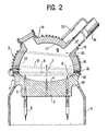
- FIG. 2 is a sectional view, on a larger scale, of the upper part of the steam generator shown in FIG. 1.
Comme l'illustre la figure 1, le générateur de vapeur surchauffée selon l'invention comporte une virole cylindrique externe 11 définissant un axe vertical. Cette virole comporte à son extrémité inférieure une chambre d'entrée 15' d'eau à vaporiser alimentée par une tuyauterie 24' et, à son extrémité supérieure, une chambre de sortie 15 de vapeur surchauffée qui communique avec une tuyauterie d'évacuation 24. Les chambres 15 et 15' sont reliées par un faisceau de tubes droits verticaux 6 qui sont raccordés respectivement à la chambre d'entrée 15' par une plaque à tubes 3' de forte épaisseur et à la chambre de sortie 15 par une plaque à tube 3 de forte épaisseur. Ainsi, l'eau à vaporiser et surchauffer circule de bas en haut dans les tubes 6 du générateur de vapeur, où elle est vaporisée et surchauffée par échange de chaleur avec un fluide plus chaud qui circule de haut en bas autour des tubes et à l'intérieur de la virole 11, entre une tubulure d'entrée 16 et une tubulure de sortie 16'.As illustrated in FIG. 1, the superheated steam generator according to the invention comprises an external
Sur la figure 2, on voit que la chambre de sortie 15 comporte une paroi externe en deux parties 8 et 2. La partie 8 constitue une zone annulaire forgée d'une seule pièce 1 avec la plaque à tubes 3, celle-ci présentant une surface concave 4 du côté de la chambre 15. La pièce 1 est traversée par des orifices tels quer5 prolongeant les tubes 6 du faisceau. La flèche 7 indique la direction de circulation de la vapeur à la sortie de ces orifices. La zone de raccordement annulaire 8 est raccordée sur son pourtour avec la seconde partie 2 de la paroi de la chambre par un cordon de soudure 10, au niveau du plan de référence 9 perpendiculaire à l'axe de la virole 11. La partie 1 se raccorde par ailleurs par la zone annulaire 8 à la virole externe 11 du générateur.In FIG. 2, it can be seen that the
La seconde partie 2 de la paroi de la chambre 15, de forme hémisphérique, de surface interne 12, est munie d'un piètement 13 de raccordement à la tuyauterie 24 d'évacuation de la vapeur et d'une tubulure 14 de trou de visite (d'autres trous de visite pouvant éventuellement être ajoutés).The
Il est apparent que lors des changements de régime de fonctionnement, il se manifeste des contraintes thermiques importantes dans la section 81 de la paroi de la chambre 15, du fait de sa grande épaisseur, dans la section 82 de la zone de raccordement entre la plaque à tubes 3 et le cordon de soudure 10, dans la section 83 de raccordement de la paroi au piètement13 d'évacuation de la vapeur, et dans la section S4 de la zone de raccordement à la virole externe 11 du générateur.It is apparent that during changes in operating regime, significant thermal stresses appear in
Conformément à l'invention, la chambre 15 de sortie de vapeur est entourée par un serpentin 21, alimenté en vapeur surchauffée par un orifice 22 percé dans sa paroi, et raccordé par un tube 23 à la tuyauterie 24 d'évacuation de la vapeur surchauffée. Ce serpentin permet de refroidir ou de réchauffer la paroi externe, suivant que la température de la vapeur pénétrant dans la chambre de sortie de vapeur diminue ou augmente, en fonction des variations de fonctionnement du générateur de vapeur.According to the invention, the
L'invention s'applique particulièrement dans les générateurs de vapeur surchauffée par échange de chaleur avec du sodium liquide dans des centrales de production d'énergie à partir d'un réacteur nucléaire surgénérateur.The invention is particularly applicable in generators of superheated steam by heat exchange with liquid sodium in power plants from a breeder nuclear reactor.
Claims (3)
Applications Claiming Priority (2)
| Application Number | Priority Date | Filing Date | Title |
|---|---|---|---|
| FR8105643A FR2502296A1 (en) | 1981-03-20 | 1981-03-20 | VAPOR EXIT CHAMBER FOR SUPERHEATED STEAM GENERATOR |
| FR8105643 | 1981-03-20 |
Publications (2)
| Publication Number | Publication Date |
|---|---|
| EP0061381A1 EP0061381A1 (en) | 1982-09-29 |
| EP0061381B1 true EP0061381B1 (en) | 1983-12-28 |
Family
ID=9256481
Family Applications (1)
| Application Number | Title | Priority Date | Filing Date |
|---|---|---|---|
| EP82400402A Expired EP0061381B1 (en) | 1981-03-20 | 1982-03-08 | Superheated steam generator |
Country Status (6)
| Country | Link |
|---|---|
| US (1) | US4445568A (en) |
| EP (1) | EP0061381B1 (en) |
| JP (1) | JPS57169501A (en) |
| DE (1) | DE3260026D1 (en) |
| ES (1) | ES510587A0 (en) |
| FR (1) | FR2502296A1 (en) |
Families Citing this family (2)
| Publication number | Priority date | Publication date | Assignee | Title |
|---|---|---|---|---|
| DE102007040793A1 (en) * | 2007-08-28 | 2009-03-05 | Behr Gmbh & Co. Kg | heat exchangers |
| US9057516B2 (en) * | 2011-11-28 | 2015-06-16 | Trimeteor Oil and Gas Corporation | Superheated steam generators |
Family Cites Families (9)
| Publication number | Priority date | Publication date | Assignee | Title |
|---|---|---|---|---|
| US466092A (en) * | 1891-12-29 | Heater | ||
| US2102424A (en) * | 1934-03-23 | 1937-12-14 | Gen Electric | Mercury power plant |
| GB800385A (en) * | 1955-12-20 | 1958-08-27 | Rolls Royce | Improvements in or relating to steam generators |
| NL246851A (en) * | 1959-01-02 | |||
| US3768554A (en) * | 1968-06-10 | 1973-10-30 | Westinghouse Electric Corp | Steam generator heated with liquid metal |
| US3596638A (en) * | 1968-10-15 | 1971-08-03 | Siemens Ag | Forced-flow steam generator to be heated by pressurized coolant of a nuclear reactor |
| US3930537A (en) * | 1974-05-06 | 1976-01-06 | The United States Of America As Represented By The United States Energy Research And Development Administration | Heat exchanger |
| US4235284A (en) * | 1976-12-16 | 1980-11-25 | The United States Of America As Represented By The United States Department Of Energy | Heat exchanger with auxiliary cooling system |
| FR2386798A1 (en) * | 1977-04-05 | 1978-11-03 | Commissariat Energie Atomique | Heat exchanger for high temps. and pressures - incorporates screen forming, with outlet chamber wall, a narrow flow space, limiting wall thermal gradient |
-
1981
- 1981-03-20 FR FR8105643A patent/FR2502296A1/en active Granted
-
1982
- 1982-03-08 DE DE8282400402T patent/DE3260026D1/en not_active Expired
- 1982-03-08 EP EP82400402A patent/EP0061381B1/en not_active Expired
- 1982-03-15 US US06/358,181 patent/US4445568A/en not_active Expired - Fee Related
- 1982-03-18 ES ES510587A patent/ES510587A0/en active Granted
- 1982-03-19 JP JP57043019A patent/JPS57169501A/en active Pending
Also Published As
| Publication number | Publication date |
|---|---|
| EP0061381A1 (en) | 1982-09-29 |
| US4445568A (en) | 1984-05-01 |
| JPS57169501A (en) | 1982-10-19 |
| FR2502296A1 (en) | 1982-09-24 |
| ES8401600A1 (en) | 1983-12-16 |
| FR2502296B1 (en) | 1984-03-09 |
| ES510587A0 (en) | 1983-12-16 |
| DE3260026D1 (en) | 1984-02-02 |
Similar Documents
| Publication | Publication Date | Title |
|---|---|---|
| EP0004218B1 (en) | Fast nuclear reactor with at least one auxiliary heat exchanger | |
| EP0688421B1 (en) | Heat exchanger device and method for cooling the inner chamber therof | |
| EP0022714B1 (en) | Fast neutrons nuclear reactor cooled by liquid metal and provided with a system for the removal of the residual heat | |
| EP3574506B1 (en) | Nuclear reactor incorporating a primary safety heat exchanger | |
| EP0246942B1 (en) | Tubular heat exchanger having double end plates | |
| EP0057643B1 (en) | Tube sheet protection device at the hot extremity of a vertical heat exchanger | |
| EP0061381B1 (en) | Superheated steam generator | |
| EP0020265B1 (en) | Heat exchanger for nuclear reactor | |
| EP0027094A1 (en) | Steam generator water chambers | |
| EP2251611A1 (en) | Modular element for radiator with heat-transfer fluid and electric radiator made up of at least one such element | |
| FR2540971A1 (en) | STEAM GENERATOR FOR A NUCLEAR REACTOR COOLED BY LIQUID METAL | |
| EP0258131B1 (en) | Emergency cooling arrangement for fast neutron reactor | |
| FR2482269A2 (en) | HIGH TEMPERATURE PERFECTED SOLAR RECEIVER | |
| CA2478755A1 (en) | Heat exchanger and manufacturing process | |
| EP0775876B1 (en) | Mixed heat exchanger coil with complex straight section | |
| EP2251612A1 (en) | Electric radiator with heat-transfer fluid made up of moulded modular elements | |
| EP0065912A1 (en) | Inner vessel for fast breeder reactors | |
| EP1593925B1 (en) | Plate heat exchanger | |
| EP0487434B1 (en) | Heat exchanger for gas fired boiler, its method of manufacture and boiler having such a heat exchanger | |
| EP3607560A1 (en) | Pump for a nuclear reactor | |
| EP0161949A1 (en) | Liquid metal-cooled nuclear reactor | |
| EP0039290A1 (en) | Thermal stress reducing device at the bottom of a vertical heat exchanger | |
| FR2713752A1 (en) | Heat exchanger using intermediate fluid in divided vessel | |
| FR2492078A1 (en) | Large condenser working at low or sub:zero temps. - contains tube bundle located between inlet and exit manifold tubes free to expand and contract with temp. changes | |
| FR2509432A1 (en) | Steam generator, esp. for fast neutron nuclear reactors - has spherical water inlet and outlet chambers possessing high resistance to mechanical stress and thermal shock |
Legal Events
| Date | Code | Title | Description |
|---|---|---|---|
| PUAI | Public reference made under article 153(3) epc to a published international application that has entered the european phase |
Free format text: ORIGINAL CODE: 0009012 |
|
| AK | Designated contracting states |
Designated state(s): BE CH DE GB IT NL |
|
| 17P | Request for examination filed |
Effective date: 19830205 |
|
| ITF | It: translation for a ep patent filed |
Owner name: JACOBACCI & PERANI S.P.A. |
|
| GRAA | (expected) grant |
Free format text: ORIGINAL CODE: 0009210 |
|
| AK | Designated contracting states |
Designated state(s): BE CH DE GB IT LI NL |
|
| REF | Corresponds to: |
Ref document number: 3260026 Country of ref document: DE Date of ref document: 19840202 |
|
| PGFP | Annual fee paid to national office [announced via postgrant information from national office to epo] |
Ref country code: DE Payment date: 19840225 Year of fee payment: 3 |
|
| PGFP | Annual fee paid to national office [announced via postgrant information from national office to epo] |
Ref country code: CH Payment date: 19840305 Year of fee payment: 3 |
|
| PGFP | Annual fee paid to national office [announced via postgrant information from national office to epo] |
Ref country code: BE Payment date: 19840331 Year of fee payment: 3 |
|
| PLBE | No opposition filed within time limit |
Free format text: ORIGINAL CODE: 0009261 |
|
| STAA | Information on the status of an ep patent application or granted ep patent |
Free format text: STATUS: NO OPPOSITION FILED WITHIN TIME LIMIT |
|
| 26N | No opposition filed | ||
| PGFP | Annual fee paid to national office [announced via postgrant information from national office to epo] |
Ref country code: NL Payment date: 19870331 Year of fee payment: 6 |
|
| PG25 | Lapsed in a contracting state [announced via postgrant information from national office to epo] |
Ref country code: GB Effective date: 19890308 |
|
| PG25 | Lapsed in a contracting state [announced via postgrant information from national office to epo] |
Ref country code: LI Effective date: 19890331 Ref country code: CH Effective date: 19890331 Ref country code: BE Effective date: 19890331 |
|
| BERE | Be: lapsed |
Owner name: COMMISSARIAT A L'ENERGIE ATOMIQUE ETABLISSEMENT D Effective date: 19890331 |
|
| PG25 | Lapsed in a contracting state [announced via postgrant information from national office to epo] |
Ref country code: NL Effective date: 19891001 |
|
| GBPC | Gb: european patent ceased through non-payment of renewal fee | ||
| NLV4 | Nl: lapsed or anulled due to non-payment of the annual fee | ||
| REG | Reference to a national code |
Ref country code: CH Ref legal event code: PL |
|
| PG25 | Lapsed in a contracting state [announced via postgrant information from national office to epo] |
Ref country code: DE Effective date: 19891201 |