EP0061367B1 - Dispositif de raccordement sur chantier de deux câbles de transmission par fibres optiques - Google Patents
Dispositif de raccordement sur chantier de deux câbles de transmission par fibres optiques Download PDFInfo
- Publication number
- EP0061367B1 EP0061367B1 EP82400293A EP82400293A EP0061367B1 EP 0061367 B1 EP0061367 B1 EP 0061367B1 EP 82400293 A EP82400293 A EP 82400293A EP 82400293 A EP82400293 A EP 82400293A EP 0061367 B1 EP0061367 B1 EP 0061367B1
- Authority
- EP
- European Patent Office
- Prior art keywords
- barrel
- cable
- splicing
- bench
- box
- Prior art date
- Legal status (The legal status is an assumption and is not a legal conclusion. Google has not performed a legal analysis and makes no representation as to the accuracy of the status listed.)
- Expired
Links
- 239000013307 optical fiber Substances 0.000 title claims description 6
- 230000005540 biological transmission Effects 0.000 claims description 5
- 239000013536 elastomeric material Substances 0.000 claims description 2
- 239000000725 suspension Substances 0.000 claims description 2
- 238000007373 indentation Methods 0.000 claims 5
- 238000012423 maintenance Methods 0.000 claims 1
- 239000000463 material Substances 0.000 claims 1
- 230000002035 prolonged effect Effects 0.000 claims 1
- 239000000835 fiber Substances 0.000 description 6
- 239000002184 metal Substances 0.000 description 6
- 238000000034 method Methods 0.000 description 5
- 230000001681 protective effect Effects 0.000 description 4
- 241001137251 Corvidae Species 0.000 description 1
- 230000002950 deficient Effects 0.000 description 1
- 239000000428 dust Substances 0.000 description 1
- 238000009434 installation Methods 0.000 description 1
- 230000000284 resting effect Effects 0.000 description 1
Images
Classifications
-
- G—PHYSICS
- G02—OPTICS
- G02B—OPTICAL ELEMENTS, SYSTEMS OR APPARATUS
- G02B6/00—Light guides; Structural details of arrangements comprising light guides and other optical elements, e.g. couplings
- G02B6/44—Mechanical structures for providing tensile strength and external protection for fibres, e.g. optical transmission cables
- G02B6/4401—Optical cables
- G02B6/4415—Cables for special applications
- G02B6/4427—Pressure resistant cables, e.g. undersea cables
- G02B6/4428—Penetrator systems in pressure-resistant devices
-
- G—PHYSICS
- G02—OPTICS
- G02B—OPTICAL ELEMENTS, SYSTEMS OR APPARATUS
- G02B6/00—Light guides; Structural details of arrangements comprising light guides and other optical elements, e.g. couplings
- G02B6/44—Mechanical structures for providing tensile strength and external protection for fibres, e.g. optical transmission cables
- G02B6/4439—Auxiliary devices
- G02B6/444—Systems or boxes with surplus lengths
-
- G—PHYSICS
- G02—OPTICS
- G02B—OPTICAL ELEMENTS, SYSTEMS OR APPARATUS
- G02B6/00—Light guides; Structural details of arrangements comprising light guides and other optical elements, e.g. couplings
- G02B6/44—Mechanical structures for providing tensile strength and external protection for fibres, e.g. optical transmission cables
- G02B6/4439—Auxiliary devices
- G02B6/4471—Terminating devices ; Cable clamps
- G02B6/4472—Manifolds
Definitions
- the present invention relates generally to devices for connecting two transmission cables each comprising, under a protective envelope, a plurality of wiring elements, and more particularly relates to a device for connecting two fiber optic cables , intended to be installed on site, that is to say for example in an underground gallery, where the splicing of the wiring elements is carried out.
- the method of splicing two fiber optic cabling elements consists in carrying out, on a so-called splicing bench, the mounting, then alignment, of two extension ends, playing the role of connectors, integral with the two wiring elements, respectively.
- These mounting and alignment operations are relatively delicate to perform, and generally make use of the operator's dexterity.
- connection device when it is necessary to carry out, on the site itself, the connection of two fiber optic cables, it is necessary to install the connection device judiciously, so as to allow the operator to carry out the different splices. in the best working conditions. In addition, the installation of the connection device must contribute to a reduction in the duration of the connection operation.
- the wiring elements once spliced must be arranged in an orderly manner inside the waterproof box, so that in case of defection of one of the wiring elements, the operator can quickly access this item.
- the present invention aims to fulfill the above objectives, by providing a device for connecting two optical fiber cables, which is particularly well suited to be installed on site.
- each wiring element will be arranged in an orderly manner inside the box, and the loop path followed by said element will provide a cable length, particularly effective for recommencing a splice deemed defective.
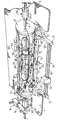
- a rectangular table intended to be installed horizontally, at the level of four lights 2, on metal parts, called crows, arranged on either side an underground gallery where two fiber optic transmission cables 4 and 4 'are connected.
- Each optical fiber cable (4; 4 ′) comprises, under a protective envelope 5, a plurality of wiring elements 6, for example seven in number.
- the structure of each wiring element 6 is for example of the type described in the European patent application already cited.
- connection process consist in stripping the ends of the cables 4 and 4 'over a predetermined length, then in rigidly holding each cable in place by means of two mechanical parts in the form of brackets 8 of which only one has been shown on the drawing, fixed on either side of the table 1.
- Each bracket 8 comprises a suspension arm 9 adjustable horizontally and vertically, and provided at its end with an opening 10 crossed without play by the casing 5 of each cable.
- the table 1 has, on one of its sides, a U-shaped notch 12 in which is positioned a bench 14 called splicing in the form of a rectangular frame, three of its sides being formed by profiles forming arms (15 , 16 and 17) internally matching the U-shape of the notch 12 of the table, respectively.
- the fourth side of the bench 14 is constituted by a rail 18 on which various tools can be driven in translation, only one of which has been shown at 20 in the drawing, intended to successively splice the various wiring elements 6.
- the different splicing tools 20 can be protected by a visor (not shown) disposed along the rail 18, thus making it possible to avoid the presence, for example of dust, on said rail.
- each of the two arms 15 and 17 consists of a part 22 pivotally mounted at one end of a fixed part 23 integral with the arm 16.
- the pivoting of each part 22 thus allows the operator to adjust as desired the height of the rail 18 on which it performs the various splicing of the wiring elements.
- the splicing bench 14 is made integral with the table 1 by means of a crosspiece 25 extending transversely with respect to the rail 18 and one end of which 26 is fixed substantially in the middle of the arm 16 of the bench and the other end of which 28 is mounted in an intermediate piece 30 fixed by any suitable system on the table 1, at its notch 12.
- connection device also includes a splicing box or pot 35, of cylindrical shape, the two end faces of which comprise two sealed flanges 37, each consisting of two half-shells fixed to one another by means of a metal ring 39, and provided with a central opening 40 receiving the casing 5 of each cable (4; 4 '). Seals (not shown) are arranged on each side of the opening 40 of each flange 37.
- the two flanges 37 of the splicing box 35 are interconnected by a metal rod in the form of a plate 42, substantially the same length as the arm 16 of the splicing bench, and ending in two legs 43, one of which only visible in the figure, rigidly fixed on the lower edges of the two flanges 37, respectively.
- the cabinet 35 is assembled with the bench 14 in the following manner.
- the rod 42 of the box 35 is mounted to bear on two supports 45 arranged on the arm 16 of the bench, substantially equidistant from the cross-member 25. More specifically, each support 45 has an orifice 47 in which the arm 16 is freely engaged, so that each support 45 is capable of moving by sliding along said arm. After positioning the two supports 45, the rod 42 of the splicing box 35 is fixed to the supports 45, by means of any suitable system, constituted for example by screws. Thus, the box 35 and the splicing bench 14 form a rigid unitary assembly.
- the connection device also comprises two cylindrical pieces forming magazines 50 each mounted around the envelope 5 of each cable (4; 4 '), that is to say outside the splicing box 35.
- Each magazine 50 is for example made of two identical parts capable of being locked together by any suitable system, constituted for example by two sets of rods connected in pairs, at one of their ends, by a metal wedge, the two rods of the same pair being capable of sliding in the two parts of the parts, respectively.
- each cylindrical magazine 50 includes a plurality of housings 54, for example in number equal to that of the wiring elements 6 of the same cable (seven in the example chosen), distributed around the periphery of the magazine.
- Each housing 54 is covered by a sealed cover (not shown) capable of being driven in translation, so as to ensure the opening and closing of the corresponding housing.
- each magazine 50 The housings 54 of each magazine 50 are intended to successively receive parts forming extension nozzles, playing the role of connectors, mounted at the ends of the various wiring elements 6. This connector mounting operation is carried out by means of tools 20 mounted on the rail 18.
- the splicing box 35 internally comprises a cylindrical part forming a barrel 60 hollowed out with a plurality of grooves 63 extending over its entire length, in a number equal to that of all the wiring elements 6 of the two cables, c ' that is to say fourteen in the example chosen, and in each of which is housed a wiring element 6.
- each wiring element 6, at the outlet of the corresponding flange 37 of the box crosses the barrel 60 while resting in the 'one of its grooves 63, leaves said barrel over a determined length, then the end of the wiring element is positioned on the rail 18 where the splicing is carried out with its homologous wiring element.
- the barrel 60 is covered with a rigid protective sheath or sleeve 68, and two pieces forming flanges 70, of respective diameter greater than that of the barrel 60, are annularly mounted at the two ends of the sleeve 68.
- Each flange 70 is hollowed out with a plurality of notches 72 distributed around its periphery, and in a number equal to that of the wiring elements 6 of the same cable, that is to say seven in the example chosen.
- each wiring element leaving the barrel 60 is introduced into a notch 72 in the flange 70 which is located at the end of the barrel where takes place the exit of said wiring element.
- the path followed by each wiring element consists of a straight line inside the barrel 60 and a loop forming an extra length ending after passing through a notch 72 of one of the two flanges 70.
- the barrel 60 and the two flanges 70 can be made of an elastomeric material, such as for example that known under the registered trademark Silastene.
- the assembly constituted by the barrel 60 and the two flanges 70 is rigidly mounted inside the box 35 by means of two attachment tabs 78 fixed on the one hand to the rod 42, for example by means of screws, and on the other hand on two metal rings 80 mounted around the sleeve 68, at the level of the two flanges 70.
- the two rings 80 are connected together by a plurality of metal bars 82 distributed annularly, and in a number equal to that of the wiring elements 6 of the same cable, that is to say seven in the example chosen.
- Each mechanical part 74 for protecting a splice is attached to one of the bars 82 by means, for example, of a plastic ring 84.
- a rod 86 is put in place, identical to that shown at 42, parallel to the latter, and mounted on the upper edge of each flange 37 by means of fastening elements, constituted for example by lugs 88 identical to those shown in 43.
- This second rod 86 allows greater stiffening of the splicing box 35.
- connection of the two transmission cables 4 and 4 ′ is completed by separating the box 35 from the bench 14, then closing the box 35 by means of a sealed cylindrical sleeve (not shown) mounted in abutment on the two flanges 37. From then the splicing bench 14 and the table 1 can be removed.
Landscapes
- Physics & Mathematics (AREA)
- General Physics & Mathematics (AREA)
- Optics & Photonics (AREA)
- Light Guides In General And Applications Therefor (AREA)
- Mechanical Coupling Of Light Guides (AREA)
Applications Claiming Priority (2)
| Application Number | Priority Date | Filing Date | Title |
|---|---|---|---|
| FR8104201 | 1981-03-03 | ||
| FR8104201A FR2501381A1 (fr) | 1981-03-03 | 1981-03-03 | Dispositif de raccordement sur chantier de deux cables de transmission par fibres optiques |
Publications (2)
| Publication Number | Publication Date |
|---|---|
| EP0061367A1 EP0061367A1 (fr) | 1982-09-29 |
| EP0061367B1 true EP0061367B1 (fr) | 1984-08-15 |
Family
ID=9255814
Family Applications (1)
| Application Number | Title | Priority Date | Filing Date |
|---|---|---|---|
| EP82400293A Expired EP0061367B1 (fr) | 1981-03-03 | 1982-02-18 | Dispositif de raccordement sur chantier de deux câbles de transmission par fibres optiques |
Country Status (6)
| Country | Link |
|---|---|
| US (1) | US4779951A (enExample) |
| EP (1) | EP0061367B1 (enExample) |
| JP (1) | JPS57158607A (enExample) |
| CA (1) | CA1192427A (enExample) |
| DE (1) | DE3260558D1 (enExample) |
| FR (1) | FR2501381A1 (enExample) |
Families Citing this family (16)
| Publication number | Priority date | Publication date | Assignee | Title |
|---|---|---|---|---|
| DE3148614C2 (de) * | 1981-12-09 | 1986-01-09 | ANT Nachrichtentechnik GmbH, 7150 Backnang | Spleissmuffe mit einer Aufnahmevorrichtung zur Positionierung von Lichtwellenleiterspleissen |
| AU1020583A (en) * | 1982-01-22 | 1983-07-28 | Preformed Line Products Company | Organiser fixture for splicing fiber optic cables |
| JPS59197005A (ja) * | 1983-04-23 | 1984-11-08 | Sumitomo Electric Ind Ltd | 光フアイバケ−ブルの接続部における余長処理方法 |
| JPS6048005A (ja) * | 1983-08-26 | 1985-03-15 | Hitachi Cable Ltd | 光ファイバ複合ケ−ブルの接続方法 |
| JPS6064301U (ja) * | 1983-10-12 | 1985-05-07 | 内田油圧機器工業株式会社 | アンロ−ド回路装置 |
| US4666240A (en) * | 1985-02-01 | 1987-05-19 | Amp Incorporated | Splice organizer for optical cable splices |
| US4685764A (en) * | 1985-02-01 | 1987-08-11 | Amp Incorporated | Splice organizer for optical cable splices |
| FR2587126B1 (fr) * | 1985-09-09 | 1987-10-23 | Lignes Telegraph Telephon | Dispositif d'eclatement d'un faisceau de fibres optiques en fibres optiques unitaires |
| GB8826202D0 (en) * | 1988-11-09 | 1988-12-14 | Telephone Cables Ltd | Clamping apparatus for array of filaments |
| US5125060A (en) * | 1991-04-05 | 1992-06-23 | Alcatel Na Cable Systems, Inc. | Fiber optic cable having spliceless fiber branch and method of making |
| US5121458A (en) * | 1991-04-05 | 1992-06-09 | Alcatel Na Cable Systems, Inc. | Preterminated fiber optic cable |
| US5210812A (en) * | 1991-04-05 | 1993-05-11 | Alcatel Na Cable Systems, Inc. | Optical fiber cable having spliced fiber branch and method of making the same |
| DE9316172U1 (de) * | 1993-10-22 | 1993-12-09 | Kabelmetal Electro Gmbh, 30179 Hannover | Muffe zur Aufnahme von Abzweig- oder Verbindungsstellen von optischen oder elektrischen Kabeln |
| US5647046A (en) * | 1995-11-20 | 1997-07-08 | Alcoa Fujikura Limited | Wedge deadend to support aerial cables |
| US5970199A (en) * | 1996-12-11 | 1999-10-19 | Act Communications, Inc. | Frame for supporting fiber optic cable splices |
| US6389213B1 (en) | 2000-02-12 | 2002-05-14 | Alcoa Fujikura Limited | Deadend wedge design |
Family Cites Families (7)
| Publication number | Priority date | Publication date | Assignee | Title |
|---|---|---|---|---|
| US4049414A (en) * | 1975-07-28 | 1977-09-20 | Corning Glass Works | Method and apparatus for splicing optical fibers |
| JPS5269638A (en) * | 1975-12-08 | 1977-06-09 | Hitachi Cable Ltd | Method and apparatus for connecting optical cables |
| IT1072041B (it) * | 1976-11-25 | 1985-04-10 | Cselt Centro Studi Lab Telecom | Sistema per l effettuazione di guinti in cavi ottici |
| US4248499A (en) * | 1978-02-23 | 1981-02-03 | Siemens Aktiengesellschaft | Splicing device for light wave guides |
| FR2420777A1 (fr) * | 1978-03-24 | 1979-10-19 | Lignes Telegraph Telephon | Procede et appareillage de raccordement de cables a fibres optiques |
| NL7900432A (nl) * | 1979-01-19 | 1980-07-22 | Nkf Groep Bv | Glasvezel verbindingsmof. |
| US4359262A (en) * | 1980-06-30 | 1982-11-16 | Northern Telecom Limited | Tray for organizing optical fiber splices and enclosures embodying such trays |
-
1981
- 1981-03-03 FR FR8104201A patent/FR2501381A1/fr active Granted
-
1982
- 1982-02-18 EP EP82400293A patent/EP0061367B1/fr not_active Expired
- 1982-02-18 DE DE8282400293T patent/DE3260558D1/de not_active Expired
- 1982-03-01 US US06/353,381 patent/US4779951A/en not_active Expired - Fee Related
- 1982-03-01 CA CA000397355A patent/CA1192427A/en not_active Expired
- 1982-03-02 JP JP57031845A patent/JPS57158607A/ja active Granted
Also Published As
| Publication number | Publication date |
|---|---|
| FR2501381A1 (fr) | 1982-09-10 |
| US4779951A (en) | 1988-10-25 |
| DE3260558D1 (en) | 1984-09-20 |
| JPS57158607A (en) | 1982-09-30 |
| EP0061367A1 (fr) | 1982-09-29 |
| CA1192427A (en) | 1985-08-27 |
| FR2501381B1 (enExample) | 1983-04-15 |
| JPH0233122B2 (enExample) | 1990-07-25 |
Similar Documents
| Publication | Publication Date | Title |
|---|---|---|
| EP0061367B1 (fr) | Dispositif de raccordement sur chantier de deux câbles de transmission par fibres optiques | |
| EP0397587B1 (fr) | Module et boîtier de raccordement de câbles à fibres optiques | |
| EP1315009B1 (fr) | Module de distribution et de connexion de fibres optiques destiné à un répartiteur optique | |
| EP0063506B1 (fr) | Dispositif de protection de fibres optiques dégagées à l'extrémité d'un élément de câble, élément de câble muni de ce dispositif, et utilisation d'un tel élément de câble | |
| CA2086373C (fr) | Dispositif de soutien et de guidage de cables de transmission de signaux electriques ou lumineux | |
| EP0538164B1 (fr) | Tête de câbles modulaire à fibres optiques de grande capacité | |
| EP0464570B1 (fr) | Dispositif modulaire pour le stockage de réserves de support de transmission sur des liaisons, notamment à fibre optique | |
| EP0146478A2 (fr) | Dispositif de raccordement de câbles, notamment à fibres optiques | |
| EP0716324B1 (fr) | Dispostif de maintien d'au moins un câble à fibres optiques et boitier d'épissurage en faisant application | |
| FR2531576A1 (fr) | Bati de raccordement et d'interface opto-electronique | |
| FR2498766A1 (fr) | Coffret de raccordement de cables de fibres optiques | |
| FR2590371A1 (fr) | Chassis de tete de cables optiques | |
| EP0348278A1 (fr) | Module de répartition et raccordement de fibres optiques | |
| EP0116480A1 (fr) | Boîte de raccordement et de brassage pour fibres optiques | |
| EP1312953A2 (fr) | Répartiteur optique à haute densité et méthode pour le jarretièrage d'un tel répartiteur | |
| FR2520517A1 (fr) | Appareil pour organiser des epissures de cables en fibres optiques | |
| EP2327833B1 (fr) | Dispositif pour protéger au moins un objet de forme générale allongée tel qu'un câble ou une conduite | |
| CA1124824A (fr) | Dispositif de raccordement des batis aux repartiteurs dans les centrales de telecommunication | |
| FR2553526A1 (fr) | Dispositif pour agencer une connexion de fibres optiques | |
| FR2688897A1 (fr) | Prise optique. | |
| FR2530829A1 (fr) | Connecteur de fibres optiques | |
| FR2682775A1 (fr) | Dispositif d'amarrage de cables a fibres optiques. | |
| EP1054279A1 (fr) | Boítier d'accès à une ou plusieurs fibres optiques dans un câble tendu | |
| FR2694642A1 (fr) | Dispositif de raccordement d'au moins un câble de transmission à des équipements électroniques. | |
| EP0803753B1 (fr) | Dispositif d'aide pour l'intervention et le rangement des fibres d'un câble optique |
Legal Events
| Date | Code | Title | Description |
|---|---|---|---|
| PUAI | Public reference made under article 153(3) epc to a published international application that has entered the european phase |
Free format text: ORIGINAL CODE: 0009012 |
|
| AK | Designated contracting states |
Designated state(s): BE CH DE GB IT NL SE |
|
| 17P | Request for examination filed |
Effective date: 19821108 |
|
| ITF | It: translation for a ep patent filed | ||
| GRAA | (expected) grant |
Free format text: ORIGINAL CODE: 0009210 |
|
| AK | Designated contracting states |
Designated state(s): BE CH DE GB IT LI NL SE |
|
| REF | Corresponds to: |
Ref document number: 3260558 Country of ref document: DE Date of ref document: 19840920 |
|
| PLBE | No opposition filed within time limit |
Free format text: ORIGINAL CODE: 0009261 |
|
| STAA | Information on the status of an ep patent application or granted ep patent |
Free format text: STATUS: NO OPPOSITION FILED WITHIN TIME LIMIT |
|
| 26N | No opposition filed | ||
| PGFP | Annual fee paid to national office [announced via postgrant information from national office to epo] |
Ref country code: GB Payment date: 19920102 Year of fee payment: 11 |
|
| PGFP | Annual fee paid to national office [announced via postgrant information from national office to epo] |
Ref country code: SE Payment date: 19920122 Year of fee payment: 11 Ref country code: CH Payment date: 19920122 Year of fee payment: 11 |
|
| PGFP | Annual fee paid to national office [announced via postgrant information from national office to epo] |
Ref country code: BE Payment date: 19920129 Year of fee payment: 11 |
|
| PGFP | Annual fee paid to national office [announced via postgrant information from national office to epo] |
Ref country code: DE Payment date: 19920218 Year of fee payment: 11 |
|
| ITTA | It: last paid annual fee | ||
| PGFP | Annual fee paid to national office [announced via postgrant information from national office to epo] |
Ref country code: NL Payment date: 19920229 Year of fee payment: 11 |
|
| PG25 | Lapsed in a contracting state [announced via postgrant information from national office to epo] |
Ref country code: GB Effective date: 19930218 |
|
| PG25 | Lapsed in a contracting state [announced via postgrant information from national office to epo] |
Ref country code: SE Effective date: 19930219 |
|
| PG25 | Lapsed in a contracting state [announced via postgrant information from national office to epo] |
Ref country code: LI Effective date: 19930228 Ref country code: CH Effective date: 19930228 Ref country code: BE Effective date: 19930228 |
|
| BERE | Be: lapsed |
Owner name: LIGNES TELEGRAPHIQUES ET TELEPHONIQUES LTT Effective date: 19930228 |
|
| PG25 | Lapsed in a contracting state [announced via postgrant information from national office to epo] |
Ref country code: NL Effective date: 19930901 |
|
| GBPC | Gb: european patent ceased through non-payment of renewal fee |
Effective date: 19930218 |
|
| NLV4 | Nl: lapsed or anulled due to non-payment of the annual fee | ||
| REG | Reference to a national code |
Ref country code: CH Ref legal event code: PL |
|
| PG25 | Lapsed in a contracting state [announced via postgrant information from national office to epo] |
Ref country code: DE Effective date: 19931103 |
|
| EUG | Se: european patent has lapsed |
Ref document number: 82400293.5 Effective date: 19930912 |