EP0061301A2 - Behälterförderer für eine Maschine zum Füllen flexibler Behälter - Google Patents
Behälterförderer für eine Maschine zum Füllen flexibler Behälter Download PDFInfo
- Publication number
- EP0061301A2 EP0061301A2 EP82301384A EP82301384A EP0061301A2 EP 0061301 A2 EP0061301 A2 EP 0061301A2 EP 82301384 A EP82301384 A EP 82301384A EP 82301384 A EP82301384 A EP 82301384A EP 0061301 A2 EP0061301 A2 EP 0061301A2
- Authority
- EP
- European Patent Office
- Prior art keywords
- filling
- container
- spout
- station
- containers
- Prior art date
- Legal status (The legal status is an assumption and is not a legal conclusion. Google has not performed a legal analysis and makes no representation as to the accuracy of the status listed.)
- Withdrawn
Links
- 230000007246 mechanism Effects 0.000 claims description 19
- 238000000034 method Methods 0.000 claims description 6
- 239000012530 fluid Substances 0.000 claims 2
- 239000012611 container material Substances 0.000 abstract description 2
- 239000000463 material Substances 0.000 description 13
- 230000005484 gravity Effects 0.000 description 4
- 230000004913 activation Effects 0.000 description 3
- 238000012163 sequencing technique Methods 0.000 description 3
- 230000001133 acceleration Effects 0.000 description 2
- 230000003213 activating effect Effects 0.000 description 2
- 230000008901 benefit Effects 0.000 description 2
- 238000010586 diagram Methods 0.000 description 2
- 241000269907 Pleuronectes platessa Species 0.000 description 1
- 230000009471 action Effects 0.000 description 1
- 238000013459 approach Methods 0.000 description 1
- 239000000428 dust Substances 0.000 description 1
- 230000006872 improvement Effects 0.000 description 1
- 239000007788 liquid Substances 0.000 description 1
- 210000003141 lower extremity Anatomy 0.000 description 1
- 230000001681 protective effect Effects 0.000 description 1
- 230000004044 response Effects 0.000 description 1
- 238000007789 sealing Methods 0.000 description 1
Images

Classifications
-
- B—PERFORMING OPERATIONS; TRANSPORTING
- B65—CONVEYING; PACKING; STORING; HANDLING THIN OR FILAMENTARY MATERIAL
- B65B—MACHINES, APPARATUS OR DEVICES FOR, OR METHODS OF, PACKAGING ARTICLES OR MATERIALS; UNPACKING
- B65B3/00—Packaging plastic material, semiliquids, liquids or mixed solids and liquids, in individual containers or receptacles, e.g. bags, sacks, boxes, cartons, cans, or jars
- B65B3/04—Methods of, or means for, filling the material into the containers or receptacles
- B65B3/045—Methods of, or means for, filling the material into the containers or receptacles for filling flexible containers having a filling and dispensing spout, e.g. containers of the "bag-in-box"-type
-
- B—PERFORMING OPERATIONS; TRANSPORTING
- B65—CONVEYING; PACKING; STORING; HANDLING THIN OR FILAMENTARY MATERIAL
- B65B—MACHINES, APPARATUS OR DEVICES FOR, OR METHODS OF, PACKAGING ARTICLES OR MATERIALS; UNPACKING
- B65B43/00—Forming, feeding, opening or setting-up containers or receptacles in association with packaging
- B65B43/12—Feeding flexible bags or carton blanks in flat or collapsed state; Feeding flat bags connected to form a series or chain
- B65B43/123—Feeding flat bags connected to form a series or chain
Definitions
- the present invention relates to apparatus and methods of filling flexible containers and, in particular, to improvvements in apparatus and methods for advancing the filling spouts of such containers into a filling station in an apparatus designed to handle containers connected-together seriatim in a continuous row.
- the prior art provides filling equipment which includes (a) conveyors for directing the continuous web formed by interconnected containers from a supply carton or other location onto a platform adjacent the filling station; (b) guides for aligning the filling spout of each container as it moves along the platform; (c) a mechanism for uncapping each container if it is capped during empty shipment, filling the container, and replacing the cap to seal the container; (d) a mechanism to seal off the spout and thereby exclude foreign matter from the container during the time between removal of the filling nozzle and capping of the filled container; and (e) means for holding each successive filling spout in position beneath the filling nozzle and for releasing such filling spouts after each container is filled.
- the container at the filling location rests either on a driven conveyor or on an inclined passive conveyor so that, as each filling spout is capped and released at the filling station, the filled container is transported away from the filling station, either by gravity or by operation of the power conveyor, and pulls with it the web of empty interconnected containers behind it.
- the use of a power conveyor may increase the; acceleration of the filled container away from the filling station to some extent, but even with this embodiment, there is a significant time lag between the release of a first filling spout and the engagement of the next successive filling spout at the filling station, reducing the overall efficiency of the equipment and the speed at which a continuous web of containers may be filled.
- the present invention takes advantage of the flexible character of the unfilled continuous web of interconnected containers by manipulating the filling spouts and allowing the flexible web material to loop, as necessary, to accommodate such independent movement.
- the present invention provides a guide, leading to the filling station, which recipro.c-ally supports and aligns each filling spout after it has been drawn onto the filling machine from the supply container, and a pair of independently actuated reciprocating spout drivers, one having a relatively short reciprocating stroke, and the other having a relatively long reciprocating stroke.
- the long stroke spout driver advances each filling spout from the beginning of the spout guide to a ready position adjacent the filling station, drawing the continuous web from the supply container onto the filling machine and guiding the next successive filling spout into the guide.
- This movement is undertaken while the short stroke spout driver is abutted against a spout which is captured at the filling nozzle and while the flexible container, related to this spout, is being filled with liquid.
- the duration of the fill is utilized to advance the continuous web of material from the supply container and over any necessary conveying and aligning means so that, while a first container is being filled, the spout of the next adjacent container is brought to the ready position.
- the cap on the waiting spout may be aligned to avoid misalignment within the filling mechanism.
- the web of material between the filling spout of the filling station and that at the ready station is allowed to form a loose loop beneath the alignment guide.
- the short stroke spout driver is retracted to a position behind the spout at the ready position to hold this spout in the ready position so that the long stroke spout drive may be retracted to engage the next successive spout.
- both the short stroke spout driver and the long stroke spout driver are advanced to push the spout from the ready station to the filling station.
- the continuous web of material, trailing the spout at the ready station must be driven forward by both the short stroke spout driver and the long stroke spout driver, in tandem, but the distance moved is so short that there is no significant delay between the time of release of the filled container and the engagement of the container advanced from the ready station, so that the'filling operation may be virtually continuous.
- the flexibility of the loop in the continuous web of material between the filled container and the spout advancing into the filling station allows independent motion of the container spouts and permits the filling of the spout advanced from the ready station to be initiated immediately, even though the filled container has not moved far enough along its conveyor, away from the filling station, to stretch the loop in the web of material taut.
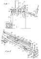
- a flexible container filling apparatus 11 of the present invention includes a primary support frame 13 and secondary elevated support frames 15, 17 and 19, each supported from the primary support frame 13 by upstanding posts.
- the secondary support frame 17 supports the electrical and pneumatic sequencing and control panel 21 which controls the operation of the apparatus 11.
- the secondary support frame 19 supports the filling nozzle 23 and its associated capping and uncapping apparatus 25.
- the secondary support frame 15 supports the container guiding and advancing mechanism for the present invention.
- the primary support frame 13 additionally mounts first and second roller frames 29 and 31, which guide the continuous web of interconnected containers 33 from a storage location, such as a box 35, onto the bed of the apparatus 11.
- the primary support frame 13 supports an inclined container unloading conveyor 37, which is used to advance filled containers, by gravity, to a container separator 39.
- the container separator 39 serves to disconnect adjacent filled containers at perforations preformed in the container web between adjacent containers, so that the containers may be deposited into protective enclosures, such as cardboard boxes, as by using the mechanism described in U.S. Patent Application Serial No.160,556, filed June 17, 1980. This latter mechanism is not shown in Figure 1.
- the location designated 41 (at which a container filling spout 25 is located), will be designated the filling station.
- the location 43 will be designated the ready station and the location 45 will be designated the pick up station.
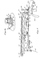
- This mechanism includes a first long stroke pneumatic cylinder 47 and a second short stroke pneumatic cylinder 49. While the short stroke cylinder 49 is of typical form, including an enclosed piston (not shown) attached to an actuating rod 51, the long stroke cylinder 47 houses a relatively short piston 48 sealed relative to the inside diameter of the cylinder 47 and attached at opposite ends to a pair of cables 53 and 55. The cables 53,55 are sheathed in smooth, plastic tubes, and thus seal at the ends of the cylinder 47 within sealing grommets 56.
- the cables 53,55 terminate at an upstanding U-shaped bracket 61 mounted on a guide block 63.
- the guide block 63 includes opposed grooves 65 which mate with a pair of guide rods 67 rigidly mounted on the secondary support frame 15. These guide rods 67 provide bearings for the grooves.65 to permit axial reciprocation of the guide block 63, under control of the long stroke cylinder 47.
- the cable arrangement 53, 55 permits the reciprocating stroke of the guide block 63 to be substantially equal in length to the overall length of the long stroke cylinder 47, obviating the need for a long piston rod extending beyond the long stroke cylinder 47 in a more typical assembly.
- the leading end of the guide block 63 forms a clevis 59 in which a pin 71 provides rotation support for a long stroke reciprocating spout driver 73.
- the long stroke spout driver 73 is held in the position shown in Figures 2 and 3 against a stop in the guide plate 63 by a spring 75, but may be rotated counter- clockwise, as viewed in these figures, if the bias of the spring 75 is overcome.
- the lower extremity of the spout driver 73 reciprocates within a channel formed between a pair of guide plates 77 and 79, which are rigidly mounted on the secondary support frame 15.
- the filling spouts of the flexible containers handled by this apparatus include circumferential grooves 81 ( Figure 3A), one of these grooves 81 being formed between a pair of annular flanges 83,85.
- the channel between the guide rods 77,79 is narrower than the outside diameter of the annular flanges 83,85, but wider than the groove 81.
- the guide plates 77,79 are undercut at their inner edge to form respective guide lips 87,89 which fit within the groove 81.
- the guide plates 77,79 thus support the upper annular flange 83 of each respective filling spout and thereby support the empty containers as they are advanced along the plates 77,79.
- contact of the lips 87,89 with the groove 81 guides each respective filling spout along the channel between the plates 77,79.
- the leading ends of the guide plates 77,79 are rigidly connected to converging alignment plates 91 and 93, respectively. These plates 91 , 93 co-operate with the rollers 29,31 to guide flexible containers and their associated filling spouts from the container or other source 35 into the previously described engagement with the alignment plates 77,79.
- the piston rod 51 of the short stroke pneumatic cylinder 49 includes a clevis 95 which mounts a short stroke spout driver 97.
- the spout driver 97 is permitted to rotate within the clevis 95 about a pin 99 and is urged for rotation in a counterclockwise direction, as viewed in Figure 2, about the pin 99 by a biasing spring 101.
- the clevis 95 includes a stop (not shown) which limits such counterclockwise rotation to the position shown in Figure 2, with a spout engaging leading edge 103 of the spout driver 97 extending across the channel formed between the alignment plates 77,79.
- the piston rod 51 When fully retracted, the piston rod 51 moves the spout abutting edge 103 to a positon, as shown in Figures 2 and 3, which permits a container spout engaging the edge 103 to rest at the ready station 43. When the piston rod 51 is fully extended, the engaging edge 103 will rest immediately adjacent the filling station 41.
- a container spout support plate 105 co-operates with the trailing edge of the guide plates 77,79 so that a spout, which is advanced to the filling station 41, will rest, with the groove 81 captured within a semi-circular opening 107 in the plate 105 during the filling operation.
- the plate 105 is mounted for rotation about an axle 109 between a first position, as shown in Figure 2, for receiving a spout and supporting the spout during the filling operation, and a second position, rotated counterclockwise, as viewed in Figure 2, about the axle 109, which second position releases the spout from the semi-circular opening 107 to permit the container to exit the filling apparatus along the conveyor 37 ( Figure 1).
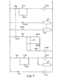
- Figure 7 is a schematic diagram of the electric sequencing control system, located in the cabinet 21 ( Figure 1) and pneumatic solenoid valves used to control the spout advancing mechanism of the present invention. This schematic diagram will be described in combination with Figures 2, 4, 5 and 6, which illustrate the mechanical sequence of operation of the equipment.
- the long stroke spout driver 73 is initially fully retracted and abutted against a container spout at the pick up station 45.
- the short stroke spout driver 51 is fully retracted abutting against an adjacent spout at the ready station 43.
- the spring 101 maintains the short stroke spout driver 97 extended across the channel between the plates 77 and 79 to hold his spout in position.
- the spring 75 ( Figure 3) holds the long stroke spout drive 73 in position, as shown, against a stop and behind the spout at the pick up station 45.
- a precapping device 27 has secured the cap, previously in a dust cover positon, onto the spout, to assure alignment of the cap with the spout as the spout enters the filling station 41.
- the plate 105 has previously been rotated counterclockwise, as viewed in Figure 2, about the axle 109 so that the semi-circular opening 107, which has been engaging a previously. filled spout, rotates away from that spout releasing the previous container.
- the plate 105 rotates clockwise about the axle 109, closing a normally open limit switch, identified on Figure 7 as 121.
- the limit switch 121 is not shown on the mechanical drawings, but its position, and that of the other limit switches described below, will be apparent from the functional description of . each. The same is true of the solenoid valves to be described. Closure of this limit switch 121 energizes the coil 119a of a relay, closing contacts 119b. Closure of the contacts 119b energizes a solenoid valve 123 which supplies pressure to the pneumatic cylinder 49 to advance the short stroke spout driver 97 to the position shown in Figure 4.
- This activation of the short stroke spout driver 97 advances the precapped spout from the ready station 43 to the filling station 41, where the spout is engaged by the filling mechanism and automatically uncapped and filled by the nozzle 25.
- the short stroke spout driver 97 advances the precapped spout from the ready station 43 to the filling station 41, where the spout is engaged by the filling mechanism and automatically uncapped and filled by the nozzle 25.
- Closure of the contacts 119b likewise actuates a relay coil 125a, which closes contacts 125b in parallel with contacts 119b. This latches the solenoid 123 to maintain the cylinder 49 extended, regardless of the condition of the contacts 119b.
- Energization of the relay coil 119a which causes the above-described advancement of the short stroke spout driver 97, also causes closure of switch contacts 119c which, in turn, activates a relay coil 127a.
- This relay coil 127a closes switch contacts 127b to activate a solenoid control valve 129 connected to the long stroke cylinder 47.
- the solenoid valve 129 advances the piston 48 and thus advances the long stroke spout driver 73 to the position shown in Figure 5, driving a spout from the pick up station 45 to the ready station 43. 'This action also pulls the next successive spout to the pick up station 45.
- the relay 127a is self-latching, closing switch contacts 127c to maintain the coil 127a activated regardless of the condition of the switch 119c.
- the long stroke spout driver 73 contacts a limit switch, opening the switch 131a and closing the switch 131b. Opening of the switch 131a deactivates the relay 127a so that the long stroke cylinder 47 remains at rest at the position shown in Figure 5.
- the long stroke cylinder 47 is double acting, and must be actuated in each direction. Thus, with the removal of pneumatic supply caused by activation of the limit switch 131a, the long stroke cylinder 47 will remain at rest.
- the long stroke spout driver 73 is adjacent a spout in the ready station 43 and the short stroke spout driver 97 remains advanced against an adjacent spout in the filling station 41. During this time period, filling of the container at the filling station 41 is in progress.
- the spring 101 snaps the short stroke spout driver 97 in a counter-clockwise direction, placing the leading edge 103 across the channel formed by the plates 77 and 79, so that the short stroke spout driver 97 can hold the spout in the ready position 43.
- the rotated position of the spout driver 97 is shown in phantom in Figure 6.
- the long and short stroke spout drivers 73,97 are in the position shown in Figure 6. Retraction of the short stroke cylinder 49 closes a noramlly open limit switch 137 activating a relay coil 139a to close contacts 139b, activating a solenoid 141 which supplies pressure to the end of the long stroke cylinder 47 opposite to that connected to the solenoid valve 129. This retracts the long stroke spout driver 73 to the position shown in Figure 2 (and in phantom in Figure 6), while the short stroke spout driver 97 holds the spout at the ready position 43 and thus holds the web of continuous containers waiting to be filled in position.
- the long stroke spout driver 73 As the long stroke spout driver 73 is retracted, it engages a spout at the pick up station 45 and is rotated by this spout, overcoming the bias of the spring 75, so that the spout driver 73 slides over the spout at the ready position 45 and then, urged by the spring 75, snaps back into its normal position, as shown in Figure 2, behind the spout at the ready position 45.
- Movement of the long stroke spout driver 73, in the retracting direction, is arrested by actuation of one of three limit switches 143a, 143b, or 143c.
- These three limit switches are placed at different locations along the length of the guide rods 67 to accommodate flexible containers of different lengths.
- the length of the containers being filled at a particular time is selected by a three-way switch 145 " which permits one of the three normally closed limit switches 143a through C to be effective in limiting the retraction of the long stroke spout driver 73.
- Opening of the appropriate limit switch 143a to c deactivates the relay coil 139a, opening the contacts 139b, and thus deactivating the solenoid valve 141 to leave the long stroke cylinder 47 at rest behind the spout in the ready position 145. It will be recognized, of course, that the normally open switch 131b, previously closed as the switch 131a was opened, has allowed activation of the relay coil 139a. Return of the long shuttle to its fully retracted position, opens the switch 131b and closes the switch 131a, setting the circuit for a repeated automatic cycle identical to that just described.
- This loop of material allows the long stroke spout driver 73 to move the spout of the container 151c to the ready station 43 immediately adjacent the filling station 41, so that the precapper 27 can adjust the cap on the container 151c.
- This forward motion of the container 151c moves the continuous web of material behind it, withdrawing an additional container from the supply carton 35 and moving the next container 151d so that is spout is at the pick up station 45.
- the time which elapses during the filling of the container 151a is used to advance the containers 151c, d, etc., forward toward the filling station 41, and to retract the spout drivers 97,73.
- the container 151a is then capped, with a cylinder 115 advanced to exclude foreign material, and the container 151a is released from the filling nozzle 25 to roll, by gravity, along the conveyor 37.
- the short stroke cylinder 49 is advanced, to the position shown in Figure 4, to advance the filling spout of the container 151b into the filling station 41, requiring only a very short movement of the web of material between the filling station 41 and the supply carton.
- the loop, previously formed is slowly eliminated, due to movement of the container 151a down the conveyor 37.
Landscapes
- Engineering & Computer Science (AREA)
- Mechanical Engineering (AREA)
- Basic Packing Technique (AREA)
- Filling Of Jars Or Cans And Processes For Cleaning And Sealing Jars (AREA)
- Containers And Plastic Fillers For Packaging (AREA)
- Auxiliary Devices For And Details Of Packaging Control (AREA)
Applications Claiming Priority (2)
| Application Number | Priority Date | Filing Date | Title |
|---|---|---|---|
| US245394 | 1981-03-19 | ||
| US06/245,394 US4386636A (en) | 1981-03-19 | 1981-03-19 | Container conveyor for flexible container filling machine |
Publications (2)
| Publication Number | Publication Date |
|---|---|
| EP0061301A2 true EP0061301A2 (de) | 1982-09-29 |
| EP0061301A3 EP0061301A3 (de) | 1983-05-11 |
Family
ID=22926476
Family Applications (1)
| Application Number | Title | Priority Date | Filing Date |
|---|---|---|---|
| EP82301384A Withdrawn EP0061301A3 (de) | 1981-03-19 | 1982-03-18 | Behälterförderer für eine Maschine zum Füllen flexibler Behälter |
Country Status (4)
| Country | Link |
|---|---|
| US (1) | US4386636A (de) |
| EP (1) | EP0061301A3 (de) |
| JP (1) | JPS57175508A (de) |
| GB (1) | GB2095205B (de) |
Cited By (1)
| Publication number | Priority date | Publication date | Assignee | Title |
|---|---|---|---|---|
| WO1998033708A3 (en) * | 1997-01-31 | 1998-11-12 | Smith David S Packaging | Apparatus for packaging flowable material in flexible sealable containers arranged in a strip |
Families Citing this family (23)
| Publication number | Priority date | Publication date | Assignee | Title |
|---|---|---|---|---|
| US4676285A (en) * | 1985-04-01 | 1987-06-30 | Liqui-Box Corporation | Uncapper for containers having friction caps carrying flexible tubes |
| US4620411A (en) * | 1985-04-01 | 1986-11-04 | Liqui-Box Corporation | Filler for bags connected in a continuous strip |
| US4874621A (en) * | 1987-02-04 | 1989-10-17 | Durkee Industrial Foods Corporation | Packaging method and system for edible solid fats and the like |
| US4892124A (en) * | 1988-12-06 | 1990-01-09 | Thomsen Peter N | Cross-cutting apparatus and conveyor for bag filling machines |
| US4962797A (en) * | 1988-12-06 | 1990-10-16 | Thomsen Peter N | Cross-cutting method for bag filling machines |
| US4865091A (en) * | 1988-12-09 | 1989-09-12 | Thomsen Peter N | Bag filling machine with side-to-side adjustment |
| US5129212A (en) * | 1990-11-08 | 1992-07-14 | Liqui-Box/B-Bar-B Corporation | Method and apparatus for automatically filling and sterilizing containers |
| US5573048A (en) * | 1994-12-05 | 1996-11-12 | Abco Automation, Inc. | Liquid filling device and method |
| US7380575B2 (en) * | 2005-12-20 | 2008-06-03 | Scholle Corporation | Filler device for filling flexible bags |
| WO2008084234A2 (en) * | 2007-01-09 | 2008-07-17 | Imi Vision Limited | Beverage dispenser |
| JP5003360B2 (ja) * | 2007-08-31 | 2012-08-15 | 凸版印刷株式会社 | バッグインボックスのバッグ自動収納包装方法及び装置 |
| US8468779B2 (en) * | 2009-05-05 | 2013-06-25 | Sealed Air Corporation (Us) | Method and apparatus for positioning, inflating, and sealing a mailer comprising an inner inflatable liner |
| US8745960B2 (en) * | 2009-05-05 | 2014-06-10 | Sealed Air Corporation (Us) | Apparatus and method for inflating and sealing an inflatable mailer |
| US8882084B2 (en) | 2010-06-29 | 2014-11-11 | Cornelius, Inc. | Variable carbonation using in-line carbonator |
| US8840092B2 (en) | 2010-06-29 | 2014-09-23 | Cornelius, Inc. | Carbonation apparatus and method for forming a carbonated beverage |
| MX2013000254A (es) | 2010-06-29 | 2013-10-28 | Imi Cornelius Inc | Aparato y metodo de carbonatacion para formar una bebida carbonatada. |
| BR112014020005A2 (pt) * | 2012-02-13 | 2019-09-24 | Anzio Harris Jerome | sistema de enchimento automático, cartucho de balão recarregável, e, método para suprir automaticamente bexigas cheias com fluido vedadas |
| US10017368B2 (en) * | 2014-11-25 | 2018-07-10 | The Wine Group, Inc. | Cap gripper |
| JP6926432B2 (ja) * | 2016-09-30 | 2021-08-25 | 凸版印刷株式会社 | 充填装置、バッグインボックスの製造装置、及びバッグの製造方法 |
| JP6926431B2 (ja) * | 2016-09-30 | 2021-08-25 | 凸版印刷株式会社 | 充填装置、バッグインボックスの製造装置、及びバッグの製造方法 |
| WO2020072753A1 (en) * | 2018-10-03 | 2020-04-09 | Liqui-Box Corporation | Auto-feed assembly for modular filling systems |
| US10934039B2 (en) * | 2018-12-31 | 2021-03-02 | Dow Global Technologies Llc | Support system for filling a flexible container |
| US12195216B1 (en) * | 2023-06-16 | 2025-01-14 | Torr Industries, Inc. | Bag transporting and filling apparatus |
Family Cites Families (2)
| Publication number | Priority date | Publication date | Assignee | Title |
|---|---|---|---|---|
| US4120134A (en) * | 1977-07-05 | 1978-10-17 | Scholle Corporation | Apparatus for and method of filling flexible containers |
| AU532109B2 (en) * | 1979-08-20 | 1983-09-15 | Flex Pack Service and Supplies Pty Ltd | Apparatus for liquid filling flexible collapsible containers |
-
1981
- 1981-03-19 US US06/245,394 patent/US4386636A/en not_active Expired - Lifetime
-
1982
- 1982-02-23 GB GB8205230A patent/GB2095205B/en not_active Expired
- 1982-03-18 EP EP82301384A patent/EP0061301A3/de not_active Withdrawn
- 1982-03-19 JP JP57045492A patent/JPS57175508A/ja active Pending
Cited By (1)
| Publication number | Priority date | Publication date | Assignee | Title |
|---|---|---|---|---|
| WO1998033708A3 (en) * | 1997-01-31 | 1998-11-12 | Smith David S Packaging | Apparatus for packaging flowable material in flexible sealable containers arranged in a strip |
Also Published As
| Publication number | Publication date |
|---|---|
| EP0061301A3 (de) | 1983-05-11 |
| US4386636A (en) | 1983-06-07 |
| JPS57175508A (en) | 1982-10-28 |
| GB2095205B (en) | 1985-01-03 |
| GB2095205A (en) | 1982-09-29 |
Similar Documents
| Publication | Publication Date | Title |
|---|---|---|
| US4386636A (en) | Container conveyor for flexible container filling machine | |
| CA1091628A (en) | Label applying apparatus | |
| US4120134A (en) | Apparatus for and method of filling flexible containers | |
| US4412876A (en) | Labeling apparatus | |
| DE3610660C1 (de) | Roentgenblattfilmkassetten-Beladegeraet | |
| US3466843A (en) | Carton closing and taping machine | |
| US4243466A (en) | Labeling apparatus | |
| US3668818A (en) | Semi-automatic closure applicator | |
| US5419095A (en) | Bag stripping apparatus | |
| DE3538893A1 (de) | Bobinenwechselvorrichtung | |
| US6080253A (en) | Method and apparatus for sealing containers | |
| EP0015529B1 (de) | Etikettiervorrichtung | |
| CN108190085B (zh) | 一种灌装泡沫填缝剂的自动打包装置及打包方法 | |
| US7938159B2 (en) | Tape applicators | |
| CN213968192U (zh) | 一种酒瓶冲瓶机 | |
| CN212458789U (zh) | 车用密封圈的检测设备 | |
| US4548022A (en) | Taping machines | |
| EP0100778B1 (de) | Vorrichtung zum automatischen Auswechseln von Druckplatten | |
| US5573048A (en) | Liquid filling device and method | |
| US4662960A (en) | Method of framing slides | |
| US4310037A (en) | Apparatus for mounting valve bags to filling spouts of filling machines | |
| CN213976898U (zh) | 一种酒瓶压盖机 | |
| US4015402A (en) | Apparatus and method for loading block-like articles into a receptacle | |
| EP0611028A1 (de) | Verfahren und Vorrichtung für das Besorgen von Stücken aus flexiblem Material von einem langen Stück | |
| US3017009A (en) | Machine for positioning the handles of containers |
Legal Events
| Date | Code | Title | Description |
|---|---|---|---|
| PUAI | Public reference made under article 153(3) epc to a published international application that has entered the european phase |
Free format text: ORIGINAL CODE: 0009012 |
|
| AK | Designated contracting states |
Designated state(s): DE FR IT |
|
| PUAL | Search report despatched |
Free format text: ORIGINAL CODE: 0009013 |
|
| AK | Designated contracting states |
Designated state(s): DE FR IT |
|
| STAA | Information on the status of an ep patent application or granted ep patent |
Free format text: STATUS: THE APPLICATION IS DEEMED TO BE WITHDRAWN |
|
| 18D | Application deemed to be withdrawn |
Effective date: 19840112 |
|
| RIN1 | Information on inventor provided before grant (corrected) |
Inventor name: ELLERT, ROGER H. |