EP0059599A1 - Ventilmechanismus für die Anwendung bei tiefen Temperaturen - Google Patents
Ventilmechanismus für die Anwendung bei tiefen Temperaturen Download PDFInfo
- Publication number
- EP0059599A1 EP0059599A1 EP82300950A EP82300950A EP0059599A1 EP 0059599 A1 EP0059599 A1 EP 0059599A1 EP 82300950 A EP82300950 A EP 82300950A EP 82300950 A EP82300950 A EP 82300950A EP 0059599 A1 EP0059599 A1 EP 0059599A1
- Authority
- EP
- European Patent Office
- Prior art keywords
- valve
- rod
- mechanism according
- housing
- valve mechanism
- Prior art date
- Legal status (The legal status is an assumption and is not a legal conclusion. Google has not performed a legal analysis and makes no representation as to the accuracy of the status listed.)
- Granted
Links
- 239000012530 fluid Substances 0.000 claims abstract description 12
- 238000005192 partition Methods 0.000 claims description 12
- 230000006835 compression Effects 0.000 claims description 5
- 238000007906 compression Methods 0.000 claims description 5
- 238000004891 communication Methods 0.000 claims description 4
- 239000007789 gas Substances 0.000 description 12
- 239000007788 liquid Substances 0.000 description 3
- 238000007789 sealing Methods 0.000 description 3
- 239000001307 helium Substances 0.000 description 2
- 229910052734 helium Inorganic materials 0.000 description 2
- SWQJXJOGLNCZEY-UHFFFAOYSA-N helium atom Chemical compound [He] SWQJXJOGLNCZEY-UHFFFAOYSA-N 0.000 description 2
- 238000012423 maintenance Methods 0.000 description 2
- 230000001105 regulatory effect Effects 0.000 description 2
- 230000000717 retained effect Effects 0.000 description 2
- 230000001276 controlling effect Effects 0.000 description 1
- 230000007423 decrease Effects 0.000 description 1
- 230000007257 malfunction Effects 0.000 description 1
Images


Classifications
-
- F—MECHANICAL ENGINEERING; LIGHTING; HEATING; WEAPONS; BLASTING
- F16—ENGINEERING ELEMENTS AND UNITS; GENERAL MEASURES FOR PRODUCING AND MAINTAINING EFFECTIVE FUNCTIONING OF MACHINES OR INSTALLATIONS; THERMAL INSULATION IN GENERAL
- F16K—VALVES; TAPS; COCKS; ACTUATING-FLOATS; DEVICES FOR VENTING OR AERATING
- F16K31/00—Actuating devices; Operating means; Releasing devices
- F16K31/12—Actuating devices; Operating means; Releasing devices actuated by fluid
- F16K31/122—Actuating devices; Operating means; Releasing devices actuated by fluid the fluid acting on a piston
- F16K31/1221—Actuating devices; Operating means; Releasing devices actuated by fluid the fluid acting on a piston one side of the piston being spring-loaded
-
- F—MECHANICAL ENGINEERING; LIGHTING; HEATING; WEAPONS; BLASTING
- F16—ENGINEERING ELEMENTS AND UNITS; GENERAL MEASURES FOR PRODUCING AND MAINTAINING EFFECTIVE FUNCTIONING OF MACHINES OR INSTALLATIONS; THERMAL INSULATION IN GENERAL
- F16K—VALVES; TAPS; COCKS; ACTUATING-FLOATS; DEVICES FOR VENTING OR AERATING
- F16K15/00—Check valves
- F16K15/02—Check valves with guided rigid valve members
- F16K15/06—Check valves with guided rigid valve members with guided stems
- F16K15/063—Check valves with guided rigid valve members with guided stems the valve being loaded by a spring
-
- F—MECHANICAL ENGINEERING; LIGHTING; HEATING; WEAPONS; BLASTING
- F16—ENGINEERING ELEMENTS AND UNITS; GENERAL MEASURES FOR PRODUCING AND MAINTAINING EFFECTIVE FUNCTIONING OF MACHINES OR INSTALLATIONS; THERMAL INSULATION IN GENERAL
- F16K—VALVES; TAPS; COCKS; ACTUATING-FLOATS; DEVICES FOR VENTING OR AERATING
- F16K15/00—Check valves
- F16K15/18—Check valves with actuating mechanism; Combined check valves and actuated valves
- F16K15/182—Check valves with actuating mechanism; Combined check valves and actuated valves with actuating mechanism
- F16K15/1825—Check valves with actuating mechanism; Combined check valves and actuated valves with actuating mechanism for check valves with flexible valve members
-
- F—MECHANICAL ENGINEERING; LIGHTING; HEATING; WEAPONS; BLASTING
- F16—ENGINEERING ELEMENTS AND UNITS; GENERAL MEASURES FOR PRODUCING AND MAINTAINING EFFECTIVE FUNCTIONING OF MACHINES OR INSTALLATIONS; THERMAL INSULATION IN GENERAL
- F16K—VALVES; TAPS; COCKS; ACTUATING-FLOATS; DEVICES FOR VENTING OR AERATING
- F16K17/00—Safety valves; Equalising valves, e.g. pressure relief valves
- F16K17/02—Safety valves; Equalising valves, e.g. pressure relief valves opening on surplus pressure on one side; closing on insufficient pressure on one side
- F16K17/14—Safety valves; Equalising valves, e.g. pressure relief valves opening on surplus pressure on one side; closing on insufficient pressure on one side with fracturing member
- F16K17/16—Safety valves; Equalising valves, e.g. pressure relief valves opening on surplus pressure on one side; closing on insufficient pressure on one side with fracturing member with fracturing diaphragm ; Rupture discs
- F16K17/162—Safety valves; Equalising valves, e.g. pressure relief valves opening on surplus pressure on one side; closing on insufficient pressure on one side with fracturing member with fracturing diaphragm ; Rupture discs of the non reverse-buckling-type
-
- F—MECHANICAL ENGINEERING; LIGHTING; HEATING; WEAPONS; BLASTING
- F16—ENGINEERING ELEMENTS AND UNITS; GENERAL MEASURES FOR PRODUCING AND MAINTAINING EFFECTIVE FUNCTIONING OF MACHINES OR INSTALLATIONS; THERMAL INSULATION IN GENERAL
- F16K—VALVES; TAPS; COCKS; ACTUATING-FLOATS; DEVICES FOR VENTING OR AERATING
- F16K31/00—Actuating devices; Operating means; Releasing devices
- F16K31/12—Actuating devices; Operating means; Releasing devices actuated by fluid
- F16K31/126—Actuating devices; Operating means; Releasing devices actuated by fluid the fluid acting on a diaphragm, bellows, or the like
- F16K31/1262—Actuating devices; Operating means; Releasing devices actuated by fluid the fluid acting on a diaphragm, bellows, or the like one side of the diaphragm being spring loaded
-
- F—MECHANICAL ENGINEERING; LIGHTING; HEATING; WEAPONS; BLASTING
- F16—ENGINEERING ELEMENTS AND UNITS; GENERAL MEASURES FOR PRODUCING AND MAINTAINING EFFECTIVE FUNCTIONING OF MACHINES OR INSTALLATIONS; THERMAL INSULATION IN GENERAL
- F16K—VALVES; TAPS; COCKS; ACTUATING-FLOATS; DEVICES FOR VENTING OR AERATING
- F16K49/00—Means in or on valves for heating or cooling
-
- Y—GENERAL TAGGING OF NEW TECHNOLOGICAL DEVELOPMENTS; GENERAL TAGGING OF CROSS-SECTIONAL TECHNOLOGIES SPANNING OVER SEVERAL SECTIONS OF THE IPC; TECHNICAL SUBJECTS COVERED BY FORMER USPC CROSS-REFERENCE ART COLLECTIONS [XRACs] AND DIGESTS
- Y10—TECHNICAL SUBJECTS COVERED BY FORMER USPC
- Y10T—TECHNICAL SUBJECTS COVERED BY FORMER US CLASSIFICATION
- Y10T137/00—Fluid handling
- Y10T137/6851—With casing, support, protector or static constructional installations
- Y10T137/7036—Jacketed
-
- Y—GENERAL TAGGING OF NEW TECHNOLOGICAL DEVELOPMENTS; GENERAL TAGGING OF CROSS-SECTIONAL TECHNOLOGIES SPANNING OVER SEVERAL SECTIONS OF THE IPC; TECHNICAL SUBJECTS COVERED BY FORMER USPC CROSS-REFERENCE ART COLLECTIONS [XRACs] AND DIGESTS
- Y10—TECHNICAL SUBJECTS COVERED BY FORMER USPC
- Y10T—TECHNICAL SUBJECTS COVERED BY FORMER US CLASSIFICATION
- Y10T137/00—Fluid handling
- Y10T137/7722—Line condition change responsive valves
- Y10T137/7837—Direct response valves [i.e., check valve type]
- Y10T137/7876—With external means for opposing bias
-
- Y—GENERAL TAGGING OF NEW TECHNOLOGICAL DEVELOPMENTS; GENERAL TAGGING OF CROSS-SECTIONAL TECHNOLOGIES SPANNING OVER SEVERAL SECTIONS OF THE IPC; TECHNICAL SUBJECTS COVERED BY FORMER USPC CROSS-REFERENCE ART COLLECTIONS [XRACs] AND DIGESTS
- Y10—TECHNICAL SUBJECTS COVERED BY FORMER USPC
- Y10T—TECHNICAL SUBJECTS COVERED BY FORMER US CLASSIFICATION
- Y10T137/00—Fluid handling
- Y10T137/7722—Line condition change responsive valves
- Y10T137/7837—Direct response valves [i.e., check valve type]
- Y10T137/7904—Reciprocating valves
- Y10T137/7922—Spring biased
- Y10T137/7929—Spring coaxial with valve
Definitions
- the present invention relates to a valve mechanism for low temperature applications, which is suitable for use at cryogenic temperatures.
- a spring type safety valve is conventionally used on pressure vessels such as boilers and compressed air tanks to prevent failure of the vessels due to excessively high pressure therein.
- pressure vessels such as boilers and compressed air tanks to prevent failure of the vessels due to excessively high pressure therein.
- a conventional cryostat for a super-conducting magnet has both a safety valve and an ordinary valve for opening and closing its outlet. Problems have been encounterd concerning maintenance of such valves and the heat loss through the valves. Particularly, in a cryostat for a magnetic floating train system, it is necessary to facilitate and expedite the maintenance of the valves to provide for the public convenience and safety.
- Another object of the invention is to provide a valve mechanism for low temperature applications suitable for use at cryogenic temperatures.
- a further object of the invention is to provide a valve mechanism for low temperature applications which will prevent failure of low temperature fluid tanks due to excessively high pressures therein.
- a valve mechanism for low temperature applications comprises, according to the present invention: valve means adapted to open and close an outlet for a low temperature fluid; an axially movable rod having one end operatively connected to the valve means and the other end extending into a normal temperature zone displaced from the outlet; a housing in which the rod is movably mounted; resilient biasing means located in the normal temperature zone and acting on the rod to bias the rod towards a position in which the valve means adopts an outlet closing disposition; and means for selectively applying a fluid under pressure to the rod to exert a force on the rod countering the biasing means, whereby to control the disposition of the valve means.
- the valve mechanism can act not only as a safety valve, the pressure at which the valve opens being determined by the bias applied by the biasing means, but also as an externally controlled valve, the opening and closing of which can be controlled by the application of the fluid under pressure.
- the tube 28 has substantially the same outer diameter as the third rod portion 26.
- the upper end 48 of tube 28 is sealingly connected to the lower end of third rod portion 26, and the lower end 50 of tube 28 is sealingly connected to valve means such as valve plug 52.
- the interior of tube 28 is preferably evacuated to reduce heat transfer between plug 52 and rod portion 26.
- Valve plug 52 is disposed in a valve chest 54.
- Valve chest 54 is mounted on tank 14 in communication with the tank outlet 56 and in communication with a gas discharge passage 58.
- Valve plug 52 confronts a valve seat 60 formed at the connection between valve chest 54 and tank outlet 56.
- Outlet 56 is closed when the valve plug 52 engages valve seat 60, and is opened when the valve plug 52 moves away from the valve seat, whereby gas from tank 14 may exit through valve chest 54 and gas discharge passage 58.
- a housing is mounted on the outside of top wall 10 of outer shell 12.
- the housing comprises first, second and third housing parts 62, 64 and 66 having aligned axial bores 68, 70 and 72, respectively, through which rod 20 is extended. Housing parts 62, 64 and 66 are stacked in the recited order on the outside of top wall 10 and secured to each other and to the top wall by means of bolts 74.
- the outer sealing periphery 76 of the first flexible partition or diaphragm 78 is sandwiched between the first and second housing parts 62 and 64.
- the centre of the diaphragm 78 is sandwiched between the second rod portion 24 and the recess 40 at the upper end 38 of the third rod portion 26, thereby sealing the valve chest 54 from the atmosphere.
- the outer sealing periphery 80 of the second flexible partition or diaphragm 82 is sandwiched between the second and third housing parts 64 and 66, and the centre of the diaphragm 82 is sandwiched between the first rod portion 22 and the recess 36 at the upper end 34 of second rod portion 24.
- a gas-tight pressure chamber 84 is formed by the inner surface of the bore 70 through second housing part 64, the outer surface of the second rod portion 24, the upper surface of the first diaphragm 78, and the lower surface of the second diaphragm 82.
- Pressure chamber 84 has a sectional area orthogonal to the axis of rod 20 which is widened at the upper side or normal temperature zone side and is narrowed at the lower side or low temperature zone side. Consequently, bore 70, i.e. pressure chamber 84, has a larger diameter upper part 70A sealed by the diaphragm 82 and a smaller diameter lower part 70B sealed by the diaphragm 78.
- Housing part 64 is radially penetrated by a high pressure gas passage 86 opening into the larger diameter part 70A of chamber 84.
- Gas passage 86 is connected to an inlet pipe 88 to introduce a pressurized gas, such as compressed air, into the pressure chamber 84.
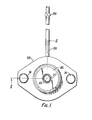
- a control valve 89 ( Figure 1) is provided on inlet pipe 88 for regulating the flow of pressurized gas into the pressure chamber.
- a tube 90 is sealingly interposed between the bore 68 of housing part 62 and an upper opening 92 of valve chest 54, thereby isolating vavle chest 54 from the vacuum zone 16 between tank 14 and outer shell 12.
- the upper end of the third housing part 66 has an integrally formed, exteriorly threaded tubular portion 94 and a cap nut 96 fastened to threaded portion 94.
- Cap nut 96 has an aperture 97 on its top wall connected to a tubular boss 98 inside the aperture. Cap nut 96 and tubular boss 98 thus form a spring seat 100.
- a resilient body such as spring 102 is interposed between cap nut 96 and an annular shoulder 104 formed as a spring seat by the narrowed upper end 30 of the first rod portion 22. Spring 102 thus urges rod 20 downwardly, i.e. toward the low temperature zone side. Valve plug 52 is thereby urged into engagement with valve seat 60 to close the outlet 56.
- An "O" ring 106 provides an airtight seal between first housing part 62 and top wall 10 to prevent air from passing through opening 18 into the space 16 between outer shell 12 and tank 14.
- the force urging valve plug 52 into engagement with valve seat 60 is adjustable by controlling the degree of the compression of the spring 102 by means of the cap nut 96.
- the interior of bore 72 of housing part 66 and the upper side of diaphragm 82 are in communication with the atmosphere through aperture 97.
- Rod 20 is urged by spring 102 downwardly, as illustrated in Figure 2, to keep the valve plug 52 normally in engagement with the valve seat 60; outlet 56 being kept closed accordingly. If an excessive pressure arises in the tank 14 and the force exerted by the pressure of the gas in the tank on valve plug 52 becomes greater than the force of spring 102, rod 20 is pushed upwardly as shown in Figure 3, and the outlet 56 is thus opened. Gas from inside the tank 14 is vented as shown by the arrows through outlet 56 and valve chest 54 into the gas discharge passage 58. When the pressure in tank 14 decreases to a predetermined value, rod 20 and valve plug 52 are moved downwardly again by spring 102 to close the outlet 56.
- the pressure in the inner tank 14 can be automatically maintained below a predetermined value by opening and closing the outlet 56. Since the spring 102 is located in the normal temperature zone, changes in the elasticity of the spring 102 due to low temperatures can be prevented. Cap nut 96, which is used to vary the compression of the spring, is also located in the normal temperature zone. The steady state pressure of spring 102 can thus be set easily and correctly. Consequently, the set pressure and reset pressure of the gas in tank 14 can be easily and correctly regulated. Any resilient means whose pressure is variable according to its length may be used in place of spring 102. Instead of cap nut 96, other means, such as set screws, may be used to vary the compression length of the resilient means.
- valve chest 54 Since the valve chest 54 is connected to discharge passage 58 and is sealed from the atmosphere by flexible partitions 82 and 78, it is not necessary to release the vented gas into the atmosphere.
Landscapes
- Engineering & Computer Science (AREA)
- General Engineering & Computer Science (AREA)
- Mechanical Engineering (AREA)
- Safety Valves (AREA)
- Lift Valve (AREA)
- Containers, Films, And Cooling For Superconductive Devices (AREA)
- Valve Housings (AREA)
- Temperature-Responsive Valves (AREA)
Applications Claiming Priority (2)
| Application Number | Priority Date | Filing Date | Title |
|---|---|---|---|
| JP56028213A JPS57144361A (en) | 1981-02-27 | 1981-02-27 | Valve mechanism for low temperature |
| JP28213/81 | 1981-02-27 |
Publications (2)
| Publication Number | Publication Date |
|---|---|
| EP0059599A1 true EP0059599A1 (de) | 1982-09-08 |
| EP0059599B1 EP0059599B1 (de) | 1986-08-20 |
Family
ID=12242357
Family Applications (1)
| Application Number | Title | Priority Date | Filing Date |
|---|---|---|---|
| EP82300950A Expired EP0059599B1 (de) | 1981-02-27 | 1982-02-24 | Ventilmechanismus für die Anwendung bei tiefen Temperaturen |
Country Status (5)
| Country | Link |
|---|---|
| US (1) | US4516599A (de) |
| EP (1) | EP0059599B1 (de) |
| JP (1) | JPS57144361A (de) |
| CA (1) | CA1186670A (de) |
| DE (1) | DE3272659D1 (de) |
Cited By (3)
| Publication number | Priority date | Publication date | Assignee | Title |
|---|---|---|---|---|
| FR2560960A1 (fr) * | 1984-03-09 | 1985-09-13 | Union Fse Robinetterie | Perfectionnement aux dispositifs de robinetterie |
| ITPR20100064A1 (it) * | 2010-07-29 | 2012-01-30 | Gea Niro Soavi Spa | Valvola di sicurezza meccanica per alte pressioni |
| KR20180058739A (ko) * | 2015-10-14 | 2018-06-01 | 포브스 마셜 프라이빗 리미티드 | 온도 감응형 차단 밸브 |
Families Citing this family (10)
| Publication number | Priority date | Publication date | Assignee | Title |
|---|---|---|---|---|
| DE3915788C2 (de) * | 1989-05-13 | 1994-09-15 | Spectrospin Ag | Kryostat mit einem Überdruckdeckel |
| US5762314A (en) * | 1993-06-08 | 1998-06-09 | O.I. Corporation | Diaphragm valve for cryogenic applications |
| IL143599A (en) * | 2001-06-06 | 2009-06-15 | Zvi Weingarten | Control valve |
| US7152557B2 (en) * | 2003-08-14 | 2006-12-26 | Amalgamated Performance Enhancements, L.L.C. | Apparatus for adjusting an operational point of an engine |
| FR2891340B1 (fr) * | 2005-09-27 | 2009-04-17 | Air Liquide | Electrovanne cryogenique |
| CN101663525B (zh) * | 2007-04-02 | 2011-11-30 | 株式会社富士金 | 内置有加热器的阀 |
| US9476516B2 (en) * | 2011-07-15 | 2016-10-25 | Mecanique Analytique Inc. | Actuator |
| CN103115189A (zh) * | 2013-02-04 | 2013-05-22 | 四川华林自控科技有限公司 | 一种节能平衡高压单座阀 |
| CN103615594A (zh) * | 2013-12-04 | 2014-03-05 | 四川锦宇化机有限公司 | 防空化高温高压四级降压阀 |
| CN110302479B (zh) * | 2019-05-30 | 2021-09-14 | 中国人民解放军空军特色医学中心 | 防窒息活门 |
Citations (7)
| Publication number | Priority date | Publication date | Assignee | Title |
|---|---|---|---|---|
| FR1070395A (fr) * | 1953-02-06 | 1954-07-23 | Tête de commande par fluide sous pression pour soupape et applications analogues | |
| FR1249396A (fr) * | 1959-11-14 | 1960-12-30 | Centre Nat Rech Scient | Vanne pour le transfert de liquides bouillant au-dessous de la température ambiante |
| GB875335A (en) * | 1958-11-20 | 1961-08-16 | Fairchild Engine & Airplane | Pressure controlled positioner |
| US3195564A (en) * | 1962-10-01 | 1965-07-20 | Union Carbide Corp | Vacuum-insulated valve for cryogenic fluids |
| US3339888A (en) * | 1964-06-29 | 1967-09-05 | Pacific Valves Inc | Cryogenic globe valve with extended body |
| DE2312103A1 (de) * | 1972-03-13 | 1973-09-27 | Bryan Donkin Co Ltd | Sicherheitsabsperrventil fuer gasversorgungssysteme |
| US3766933A (en) * | 1970-07-27 | 1973-10-23 | Broughton Corp | Rolling diaphragm vacuum control |
Family Cites Families (6)
| Publication number | Priority date | Publication date | Assignee | Title |
|---|---|---|---|---|
| US2456165A (en) * | 1945-03-19 | 1948-12-14 | Dalkin Company A | Valve mounting |
| US3143134A (en) * | 1960-12-12 | 1964-08-04 | John J Karpis | Fluid regulator |
| US3100399A (en) * | 1961-07-21 | 1963-08-13 | Worthington Corp | Pneumatic servo-positioner unit |
| US3358463A (en) * | 1966-07-15 | 1967-12-19 | Lockheed Aircraft Corp | Integrated superconducting magnetcryostat system |
| GB2043831B (en) * | 1979-03-03 | 1982-11-10 | Plessey Co Ltd | Rolling diaphragms |
| US4442859A (en) * | 1981-05-13 | 1984-04-17 | Otis Engineering Corporation | Control valve |
-
1981
- 1981-02-27 JP JP56028213A patent/JPS57144361A/ja active Granted
-
1982
- 1982-02-23 US US06/351,509 patent/US4516599A/en not_active Expired - Lifetime
- 1982-02-24 DE DE8282300950T patent/DE3272659D1/de not_active Expired
- 1982-02-24 EP EP82300950A patent/EP0059599B1/de not_active Expired
- 1982-02-26 CA CA000397209A patent/CA1186670A/en not_active Expired
Patent Citations (7)
| Publication number | Priority date | Publication date | Assignee | Title |
|---|---|---|---|---|
| FR1070395A (fr) * | 1953-02-06 | 1954-07-23 | Tête de commande par fluide sous pression pour soupape et applications analogues | |
| GB875335A (en) * | 1958-11-20 | 1961-08-16 | Fairchild Engine & Airplane | Pressure controlled positioner |
| FR1249396A (fr) * | 1959-11-14 | 1960-12-30 | Centre Nat Rech Scient | Vanne pour le transfert de liquides bouillant au-dessous de la température ambiante |
| US3195564A (en) * | 1962-10-01 | 1965-07-20 | Union Carbide Corp | Vacuum-insulated valve for cryogenic fluids |
| US3339888A (en) * | 1964-06-29 | 1967-09-05 | Pacific Valves Inc | Cryogenic globe valve with extended body |
| US3766933A (en) * | 1970-07-27 | 1973-10-23 | Broughton Corp | Rolling diaphragm vacuum control |
| DE2312103A1 (de) * | 1972-03-13 | 1973-09-27 | Bryan Donkin Co Ltd | Sicherheitsabsperrventil fuer gasversorgungssysteme |
Cited By (4)
| Publication number | Priority date | Publication date | Assignee | Title |
|---|---|---|---|---|
| FR2560960A1 (fr) * | 1984-03-09 | 1985-09-13 | Union Fse Robinetterie | Perfectionnement aux dispositifs de robinetterie |
| ITPR20100064A1 (it) * | 2010-07-29 | 2012-01-30 | Gea Niro Soavi Spa | Valvola di sicurezza meccanica per alte pressioni |
| WO2012014095A1 (en) | 2010-07-29 | 2012-02-02 | Gea Niro Soavi S.P.A. | High pressure mechanical safety valve |
| KR20180058739A (ko) * | 2015-10-14 | 2018-06-01 | 포브스 마셜 프라이빗 리미티드 | 온도 감응형 차단 밸브 |
Also Published As
| Publication number | Publication date |
|---|---|
| EP0059599B1 (de) | 1986-08-20 |
| JPS57144361A (en) | 1982-09-06 |
| US4516599A (en) | 1985-05-14 |
| JPS6346312B2 (de) | 1988-09-14 |
| DE3272659D1 (en) | 1986-09-25 |
| CA1186670A (en) | 1985-05-07 |
Similar Documents
| Publication | Publication Date | Title |
|---|---|---|
| US5127237A (en) | Expansion valve | |
| EP0257811B1 (de) | Durchflussventil | |
| EP1020779B1 (de) | Ventil mit einem elastomeren Element | |
| EP0059599A1 (de) | Ventilmechanismus für die Anwendung bei tiefen Temperaturen | |
| US6901952B2 (en) | Gas flow regulation system | |
| US2693822A (en) | Piston operated valve with leak detection means | |
| US3207175A (en) | Pressure regulator | |
| US3211174A (en) | Pressure relief or blowdown valve | |
| EP0309081B1 (de) | Pneumatisch gesteuertes Zweikolbenventil | |
| US5063784A (en) | Refrigerant transducer assembly and method | |
| JPH0242284A (ja) | 高温用安全逃し装置 | |
| US5036878A (en) | Gas-cylinder relief valve | |
| US5094267A (en) | Pressure balanced valve spindle | |
| US7806136B2 (en) | Wafer-type direct-acting valve | |
| US3595263A (en) | Pilot actuated unbalanced piston relief valve | |
| US5158111A (en) | Pilot valve for pneumatic control systems with improved poppet | |
| US4671319A (en) | Autonomous assistance device for a safety valve | |
| US4135697A (en) | Low pressure pilot valve | |
| US4991620A (en) | Tank blanketing valve | |
| US4176679A (en) | Check valve | |
| US4354664A (en) | Fail-safe valve | |
| US10268213B1 (en) | Check valve with pilot tube pressure sensing | |
| EP0050898B1 (de) | Druckregel- und Absperrventil | |
| US3614966A (en) | Pilot operated evaporator pressure regulator valve | |
| EP0341031A2 (de) | Ventilantrieb |
Legal Events
| Date | Code | Title | Description |
|---|---|---|---|
| PUAI | Public reference made under article 153(3) epc to a published international application that has entered the european phase |
Free format text: ORIGINAL CODE: 0009012 |
|
| AK | Designated contracting states |
Designated state(s): CH DE FR GB LI NL |
|
| 17P | Request for examination filed |
Effective date: 19830211 |
|
| RAP1 | Party data changed (applicant data changed or rights of an application transferred) |
Owner name: KABUSHIKI KAISHA TOSHIBA |
|
| GRAA | (expected) grant |
Free format text: ORIGINAL CODE: 0009210 |
|
| AK | Designated contracting states |
Kind code of ref document: B1 Designated state(s): CH DE FR GB LI NL |
|
| ET | Fr: translation filed | ||
| REF | Corresponds to: |
Ref document number: 3272659 Country of ref document: DE Date of ref document: 19860925 |
|
| PLBE | No opposition filed within time limit |
Free format text: ORIGINAL CODE: 0009261 |
|
| STAA | Information on the status of an ep patent application or granted ep patent |
Free format text: STATUS: NO OPPOSITION FILED WITHIN TIME LIMIT |
|
| 26N | No opposition filed | ||
| PGFP | Annual fee paid to national office [announced via postgrant information from national office to epo] |
Ref country code: FR Payment date: 19911223 Year of fee payment: 11 |
|
| PGFP | Annual fee paid to national office [announced via postgrant information from national office to epo] |
Ref country code: GB Payment date: 19920214 Year of fee payment: 11 |
|
| PGFP | Annual fee paid to national office [announced via postgrant information from national office to epo] |
Ref country code: CH Payment date: 19920224 Year of fee payment: 11 |
|
| PGFP | Annual fee paid to national office [announced via postgrant information from national office to epo] |
Ref country code: NL Payment date: 19920229 Year of fee payment: 11 |
|
| PGFP | Annual fee paid to national office [announced via postgrant information from national office to epo] |
Ref country code: DE Payment date: 19920331 Year of fee payment: 11 |
|
| PG25 | Lapsed in a contracting state [announced via postgrant information from national office to epo] |
Ref country code: GB Effective date: 19930224 |
|
| PG25 | Lapsed in a contracting state [announced via postgrant information from national office to epo] |
Ref country code: LI Effective date: 19930228 Ref country code: CH Effective date: 19930228 |
|
| PG25 | Lapsed in a contracting state [announced via postgrant information from national office to epo] |
Ref country code: NL Effective date: 19930901 |
|
| NLV4 | Nl: lapsed or anulled due to non-payment of the annual fee | ||
| GBPC | Gb: european patent ceased through non-payment of renewal fee |
Effective date: 19930224 |
|
| PG25 | Lapsed in a contracting state [announced via postgrant information from national office to epo] |
Ref country code: FR Effective date: 19931029 |
|
| REG | Reference to a national code |
Ref country code: CH Ref legal event code: PL |
|
| PG25 | Lapsed in a contracting state [announced via postgrant information from national office to epo] |
Ref country code: DE Effective date: 19931103 |
|
| REG | Reference to a national code |
Ref country code: FR Ref legal event code: ST |