EP0059157B1 - Rotierende Schneidvorrichtung für Materialbahnen - Google Patents
Rotierende Schneidvorrichtung für Materialbahnen Download PDFInfo
- Publication number
- EP0059157B1 EP0059157B1 EP82730014A EP82730014A EP0059157B1 EP 0059157 B1 EP0059157 B1 EP 0059157B1 EP 82730014 A EP82730014 A EP 82730014A EP 82730014 A EP82730014 A EP 82730014A EP 0059157 B1 EP0059157 B1 EP 0059157B1
- Authority
- EP
- European Patent Office
- Prior art keywords
- knife
- knife cylinder
- cylinders
- cutting
- cylinder
- Prior art date
- Legal status (The legal status is an assumption and is not a legal conclusion. Google has not performed a legal analysis and makes no representation as to the accuracy of the status listed.)
- Expired
Links
- 238000005520 cutting process Methods 0.000 title claims description 33
- 230000000694 effects Effects 0.000 description 9
- 239000007787 solid Substances 0.000 description 8
- 238000005452 bending Methods 0.000 description 4
- 230000009467 reduction Effects 0.000 description 3
- 230000008878 coupling Effects 0.000 description 2
- 238000010168 coupling process Methods 0.000 description 2
- 238000005859 coupling reaction Methods 0.000 description 2
- 230000007246 mechanism Effects 0.000 description 2
- 230000001133 acceleration Effects 0.000 description 1
- 230000009471 action Effects 0.000 description 1
- 230000008901 benefit Effects 0.000 description 1
- 230000007547 defect Effects 0.000 description 1
- 230000002708 enhancing effect Effects 0.000 description 1
- 238000000034 method Methods 0.000 description 1
- 230000004048 modification Effects 0.000 description 1
- 238000012986 modification Methods 0.000 description 1
Images


Classifications
-
- B—PERFORMING OPERATIONS; TRANSPORTING
- B26—HAND CUTTING TOOLS; CUTTING; SEVERING
- B26D—CUTTING; DETAILS COMMON TO MACHINES FOR PERFORATING, PUNCHING, CUTTING-OUT, STAMPING-OUT OR SEVERING
- B26D7/00—Details of apparatus for cutting, cutting-out, stamping-out, punching, perforating, or severing by means other than cutting
- B26D7/26—Means for mounting or adjusting the cutting member; Means for adjusting the stroke of the cutting member
- B26D7/2628—Means for adjusting the position of the cutting member
- B26D7/265—Journals, bearings or supports for positioning rollers or cylinders relatively to each other
-
- B—PERFORMING OPERATIONS; TRANSPORTING
- B26—HAND CUTTING TOOLS; CUTTING; SEVERING
- B26D—CUTTING; DETAILS COMMON TO MACHINES FOR PERFORATING, PUNCHING, CUTTING-OUT, STAMPING-OUT OR SEVERING
- B26D1/00—Cutting through work characterised by the nature or movement of the cutting member or particular materials not otherwise provided for; Apparatus or machines therefor; Cutting members therefor
- B26D1/56—Cutting through work characterised by the nature or movement of the cutting member or particular materials not otherwise provided for; Apparatus or machines therefor; Cutting members therefor involving a cutting member which travels with the work otherwise than in the direction of the cut, i.e. flying cutter
- B26D1/62—Cutting through work characterised by the nature or movement of the cutting member or particular materials not otherwise provided for; Apparatus or machines therefor; Cutting members therefor involving a cutting member which travels with the work otherwise than in the direction of the cut, i.e. flying cutter and is rotating about an axis parallel to the line of cut, e.g. mounted on a rotary cylinder
- B26D1/626—Cutting through work characterised by the nature or movement of the cutting member or particular materials not otherwise provided for; Apparatus or machines therefor; Cutting members therefor involving a cutting member which travels with the work otherwise than in the direction of the cut, i.e. flying cutter and is rotating about an axis parallel to the line of cut, e.g. mounted on a rotary cylinder for thin material, e.g. for sheets, strips or the like
-
- B—PERFORMING OPERATIONS; TRANSPORTING
- B26—HAND CUTTING TOOLS; CUTTING; SEVERING
- B26D—CUTTING; DETAILS COMMON TO MACHINES FOR PERFORATING, PUNCHING, CUTTING-OUT, STAMPING-OUT OR SEVERING
- B26D7/00—Details of apparatus for cutting, cutting-out, stamping-out, punching, perforating, or severing by means other than cutting
- B26D7/26—Means for mounting or adjusting the cutting member; Means for adjusting the stroke of the cutting member
- B26D7/2614—Means for mounting the cutting member
-
- Y—GENERAL TAGGING OF NEW TECHNOLOGICAL DEVELOPMENTS; GENERAL TAGGING OF CROSS-SECTIONAL TECHNOLOGIES SPANNING OVER SEVERAL SECTIONS OF THE IPC; TECHNICAL SUBJECTS COVERED BY FORMER USPC CROSS-REFERENCE ART COLLECTIONS [XRACs] AND DIGESTS
- Y10—TECHNICAL SUBJECTS COVERED BY FORMER USPC
- Y10T—TECHNICAL SUBJECTS COVERED BY FORMER US CLASSIFICATION
- Y10T83/00—Cutting
- Y10T83/465—Cutting motion of tool has component in direction of moving work
- Y10T83/4766—Orbital motion of cutting blade
- Y10T83/4795—Rotary tool
- Y10T83/483—With cooperating rotary cutter or backup
- Y10T83/4836—With radial overlap of the cutting members
-
- Y—GENERAL TAGGING OF NEW TECHNOLOGICAL DEVELOPMENTS; GENERAL TAGGING OF CROSS-SECTIONAL TECHNOLOGIES SPANNING OVER SEVERAL SECTIONS OF THE IPC; TECHNICAL SUBJECTS COVERED BY FORMER USPC CROSS-REFERENCE ART COLLECTIONS [XRACs] AND DIGESTS
- Y10—TECHNICAL SUBJECTS COVERED BY FORMER USPC
- Y10T—TECHNICAL SUBJECTS COVERED BY FORMER US CLASSIFICATION
- Y10T83/00—Cutting
- Y10T83/929—Tool or tool with support
- Y10T83/9372—Rotatable type
Definitions
- This invention relates to a rotary web-cutting apparatus.
- FIGs 1, 2 and 3 of the present description there are shown an upper solid knife cylinder 1, a lower solid knife cylinder 2, knives 5 and 6 secured to the external circumference of the cylinders by means of bolts 3 and 4, both ends of the cylinders being rotatably supported by frames 8 and 9 through bearings 7 so that the cylinders can rotate in the same phase angles by means of gears 10 and 11 affixed to both ends thereof.
- a gear 12 is affixed to one shaft end of the lower solid knife cylinder through the bearing 7 and is in meshing engagement with a gear 13 so that both the knife cylinders 1 and 2 can be driven by a DC motor 14 connected to the gear 13 and the continuously travelling cardboard sheet 15 can be cut off when the upper knife 5 of the upper solid knife cylinder comes in meshing with the lower knife 6 of the lower solid knife cylinder.
- both the knife cylinders 1 and 2 are so designed that they can be rotated at variable speed by control means (not shown in the drawings). Namely, as shown in Fig. 3, while the upper knife 5 starts rotating in the direction of the arrow from its stop position and moves for the zone (I) until both the knives come in contact, it is accelerated in speed until its rotary speed becomes equal to the travelling speed of the cardboard sheet 15, and then, in the zone (11), it is rotated at the same speed as the travelling speed of the cardboard sheet 15, and after cutting off, it is reduced in speed in the zone (III) until its initial topmost stop position is reached, thus completing one rotation thereof. In this case, in . order to cut off the cardboard sheet 15 to desired lengths, it is sufficient to adjust by suitable means the time during which the knives are slowing down and stopped. By carrying out the aforesaid operation repeatedly, it is possible to cut off the cardboard sheet 15 in a continuous sequence.
- the present invention is concerned with improving such conventional rotary web-cutting apparatus having the aforesaid disadvantage.
- the object of the present invention is to provide a rotary web-cutting apparatus with improvements in cutting effect and reduction of driving power consumption.
- numeral 16 designates an upper hollow knife cylinder
- 17 a lower hollow knife cylinder
- 18 and 19 are upper and lower knives respectively.
- the knives 18 and 19 are secured to the external circumference of both knife cylinders 16 and 17 by means of bolts 20.
- Shafts 21 and 22 are so provided as to extend through the hollow portion of the upper and lower hollow knife cylinders 16 and 17 respectively.
- the ends of both shafts 21 and 22 are firmly fixed by means of tapered sleeves 32 disposed at left and right frames 23 and 24 respectively.
- Bearings 25 are interposed inside each end of the upper and lower hollow knife cylinders 16 and 17 so as to have the upper and lower hollow knife cylinders rotatably supported by the shafts 21 and 22 respectively.
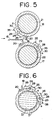
- Holes (a) are formed in the center of the upper and lower hollow knife cylinders 16 and 17 as shown in Figs. 4 and 5 and rollers 28 rotatably supported by shafts 29 are arranged in the holes (a). These shafts 29 are supported by brackets 30 affixed to the upper and lower hollow knife cylinders 16 and 17 by means of bolts 35. The rollers 28 in the holes (a) are brought into contact with the shafts 21 and 22 so that a load to be received by the upper and lower hollow knife cylinders can be borne by the shafts 21 and 22. In meshing engagement are gears 26 and 27 secured to both ends of the upper hollow knife cylinder 16 and the lower hollow knife cylinder 17 so that the upper and lower hollow knife cylinders can rotate in the same phase angle. One of the gears 27 at one end of the lower hollow knife cylinder is in meshing engagement with a gear 31 to which is connected a DC motor 34 through a coupling 33.
- Fig. 4 shows the structure and position of the knives 18, 19 and also explains in more detail the relationship between the additional support structure (shafts 29, brackets 30, holes a, etc.) and the shafts 21, 22.
- said explanation neglects the correct positional relationship between the knives 18, 19 and rollers 28, illustrated in Figs. 5 and 6.
- Fig. 6 shows another preferred embodiment wherein there are provided two rollers 28 in the center of the lower hollow knife cylinder 17, as distinguished from the previous embodiment provided with one roller.
- two rollers 28 By providing two rollers in this manner, it is possible to spread cutting load by sharing, instead of one roller alone.
- more than three rollers or a plurality of rollers 28 may be provided in the external circumference of the lower hollow knife cylinder 17 in the same manner. In this case, such rollers have only to be arranged at suitable intervals in the circumferential as well as the axial direction.
- the upper and lower hollow knife cylinders 16 and 17 are caused to rotate at variable speed by a control mechanism (not shown) through the DC motor 34, coupling 33 and gears 31, 27 and 26 in the same manner as conventional apparatus so that the cardboard sheet 15 can be cut off to any suitable length.
- cutting load W, support span I and modulus of longitudinal elasticity E are the same values in both conventional apparatus and the present invention.
- second moment of area of the hollow knife cylinders is 1 1 and that of the shafts is 1 2
- the hollow knife cylinders are supported by the shafts through bearings at both ends thereof and the roll in the center of the cylinders is provided in the direction of action of cutting load, such cutting load must act on the hollow knife cylinders and shafts.
- polar moment of inertia of area Ip of the knife cylinder with a circular cross section is expressed as on the basis of On the assumption that the external diameter of a conventional solid knife cylinder is D while that of the hollow knife cylinder of the present invention is also D and its internal diameter is d,
- I P of conventional solid cylinder is expressed as which may be termed as l p1 .
- I P of the hollow knife cylinder of the present invention is expressed as which may be termed as I P2 .
- bending rigidity can be improved quite satisfactorily and at the same time, power consumption can be reduced to a remarkable degree.
Landscapes
- Life Sciences & Earth Sciences (AREA)
- Forests & Forestry (AREA)
- Engineering & Computer Science (AREA)
- Mechanical Engineering (AREA)
- Making Paper Articles (AREA)
- Perforating, Stamping-Out Or Severing By Means Other Than Cutting (AREA)
Claims (1)
- Rotationsschneidmaschine bestehend aus zwei hohlen Messerzylindern (16, 17), von denen jedes mit einem Schneidmesser (18, 19) versehen und so ausgebildet ist, daß es in zueinander gegenläufigen Richtungen in Drehung versetzt wird, aus Wellen (21, 22), die sich durch den hohlen Abschnitt der Messerzylinder erstrecken und deren beide Enden von Rahmen (23, 24) gehalten werden, aus Endlager (25), die an den beiden 'Enden der Messerzylinder liegen, und aus zumindest einer jedem Messerzylinder zugeordneten Tragrolle (28), wobei jede Tragrolle an einer der Wellen und dem entsprechenden Messerzylinder drehbar gelagert ist und mit seiner Drehfläche mit dem Umfang der anderen Welle und dem entsprechenden Messerzylinder derart in Kontakt gehalten wird, daß der Messerzylinder gegen Durchbiegen unterstützt wird, dadurch gekennzeichnet, daß die Endlager (25) zum drehbaren Halten jedes Messerzylinders (16, 17) an der entsprechenden Welle (21, 22) angeordnet sind und daß zumindest die Tragrolle (28) drehbar an jedem Messerzylinder (16, 17) zwischen den Endlagern (25) mittels einer Klammer (30) eingesetzt ist, durch die die Tragrolle gegen die Aussenwand des hohlen Messerzylinders (16,17) derart gehalten wird, daß sich ein Abschnitt des Rollendrehumfangs nach innen durch eine Öffnung (a) im hohlen Messerzylinder (16, 17) über die Innenwand hinaus erstreckt, um mit dem äußers Umfang der jeweiligen Welle (21, 22) in eingreifenden Kontakt zu kommen.
Applications Claiming Priority (2)
| Application Number | Priority Date | Filing Date | Title |
|---|---|---|---|
| JP56024230A JPS57138591A (en) | 1981-02-23 | 1981-02-23 | Rotary type laminar material cutter |
| JP24230/81 | 1981-02-23 |
Publications (3)
| Publication Number | Publication Date |
|---|---|
| EP0059157A2 EP0059157A2 (de) | 1982-09-01 |
| EP0059157A3 EP0059157A3 (en) | 1984-05-23 |
| EP0059157B1 true EP0059157B1 (de) | 1987-10-07 |
Family
ID=12132451
Family Applications (1)
| Application Number | Title | Priority Date | Filing Date |
|---|---|---|---|
| EP82730014A Expired EP0059157B1 (de) | 1981-02-23 | 1982-02-17 | Rotierende Schneidvorrichtung für Materialbahnen |
Country Status (5)
| Country | Link |
|---|---|
| US (1) | US4420999A (de) |
| EP (1) | EP0059157B1 (de) |
| JP (1) | JPS57138591A (de) |
| BR (1) | BR8200876A (de) |
| DE (1) | DE3277440D1 (de) |
Families Citing this family (16)
| Publication number | Priority date | Publication date | Assignee | Title |
|---|---|---|---|---|
| JPS57138591A (en) * | 1981-02-23 | 1982-08-26 | Mitsubishi Heavy Ind Ltd | Rotary type laminar material cutter |
| AT372881B (de) * | 1982-03-05 | 1983-11-25 | Voest Alpine Ag | Anlage zum warmwalzen von band- oder tafelfoermigem walzgut |
| JPS59109496U (ja) * | 1983-01-14 | 1984-07-24 | 三菱重工業株式会社 | 回転式ドラムシヤ |
| US4548112A (en) * | 1984-07-20 | 1985-10-22 | Marquip, Inc. | Web cutting |
| JPS61288994A (ja) * | 1985-06-17 | 1986-12-19 | レンゴ−株式会社 | ロ−タリカツタ |
| AU556497B1 (en) * | 1985-07-05 | 1986-11-06 | Mitsubishi Jukogyo Kabushiki Kaisha | Mounting means for stamping device |
| DE3608111C1 (de) * | 1986-03-12 | 1987-10-01 | Bielomatik Leuze & Co | Querschneider fuer Bahnmaterialien |
| JPH0716914B2 (ja) * | 1987-06-30 | 1995-03-01 | 三菱重工業株式会社 | ロ−タリカツタ |
| DE3937286A1 (de) * | 1989-11-09 | 1991-05-16 | Hoechst Ag | Bandwechselvorrichtung |
| US5189935A (en) * | 1990-11-09 | 1993-03-02 | Richard Rosemann | Rotary cutting die assembly |
| DE4223566C2 (de) * | 1992-07-17 | 1995-09-14 | Bielomatik Leuze & Co | Messerwalze für Schneideinrichtungen sowie Verfahren zur wenigstens teilfertigen Herstellung einer Messerwalze |
| IT1302771B1 (it) * | 1998-09-29 | 2000-09-29 | Danieli & C Ohg Sp | Cesoia a rotazione continua |
| SE527838C2 (sv) * | 2004-07-02 | 2006-06-20 | Sandvik Intellectual Property | En rotationskniv och en rotationsknivanordning försedd med en dylik rotationskniv |
| US7621238B2 (en) * | 2005-11-23 | 2009-11-24 | Bradford White Corporation | Water heater and system for insulating same |
| US9993932B2 (en) * | 2011-09-09 | 2018-06-12 | Vits International, Inc. | Rotary cutter |
| WO2016037764A1 (en) * | 2014-09-10 | 2016-03-17 | Fosber S.P.A. | Device for transverse cutting of a web material and machine containing said device |
Family Cites Families (4)
| Publication number | Priority date | Publication date | Assignee | Title |
|---|---|---|---|---|
| US2238542A (en) * | 1940-08-03 | 1941-04-15 | United Eng Foundry Co | Shear |
| GB725922A (en) * | 1952-10-21 | 1955-03-09 | Jagenberg Werke Ag | Improvements in cross cutter machines with rotary cutter drums |
| US3683734A (en) * | 1970-06-25 | 1972-08-15 | Bhs Bayerische Berg | Roller bearing |
| JPS57138591A (en) * | 1981-02-23 | 1982-08-26 | Mitsubishi Heavy Ind Ltd | Rotary type laminar material cutter |
-
1981
- 1981-02-23 JP JP56024230A patent/JPS57138591A/ja active Granted
-
1982
- 1982-02-17 DE DE8282730014T patent/DE3277440D1/de not_active Expired
- 1982-02-17 EP EP82730014A patent/EP0059157B1/de not_active Expired
- 1982-02-18 US US06/349,970 patent/US4420999A/en not_active Expired - Lifetime
- 1982-02-18 BR BR8200876A patent/BR8200876A/pt unknown
Also Published As
| Publication number | Publication date |
|---|---|
| EP0059157A3 (en) | 1984-05-23 |
| JPS57138591A (en) | 1982-08-26 |
| JPS6146278B2 (de) | 1986-10-13 |
| DE3277440D1 (en) | 1987-11-12 |
| BR8200876A (pt) | 1982-12-28 |
| EP0059157A2 (de) | 1982-09-01 |
| US4420999A (en) | 1983-12-20 |
Similar Documents
| Publication | Publication Date | Title |
|---|---|---|
| EP0059157B1 (de) | Rotierende Schneidvorrichtung für Materialbahnen | |
| US5328437A (en) | Paper web folder with laterally shiftable formers | |
| US4004479A (en) | Scrap chopper | |
| JP2680041B2 (ja) | 打抜き機等のロールを調節するための組立体 | |
| US5727724A (en) | Method and apparatus for transporting a web material | |
| GB1577882A (en) | Vacuum roller | |
| CA2177797C (en) | Arrangement in connection with a spreader roll drive | |
| US5047003A (en) | Apparatus for zigzag folding a paper web | |
| JPH0710371A (ja) | 縦折りフォーマへの複層ウェブリボン進入装置 | |
| US4696212A (en) | Rotary cutter | |
| DE2542402A1 (de) | Papierbahnschneider | |
| JP3692992B2 (ja) | 3分割版胴装置 | |
| EP0957056B1 (de) | Verstellbare Schneidleiste für einen Falzapparat einer Rollenrotationsdruckmaschine | |
| EP0333675A2 (de) | Transport- und Faltzylinder für die Papier- und Pappenindustrie | |
| JPH0796419B2 (ja) | 折畳装置のフォーマー | |
| JPS6146277B2 (de) | ||
| CA1058132A (en) | Scrap chopper | |
| US20050070416A1 (en) | Flying tuck folding device | |
| GB2030912A (en) | A processing arrangement suitable for treating moving webs of material | |
| JPH0569390A (ja) | 回転ドラム式切断装置 | |
| US4279184A (en) | Apparatus for processing longitudinally-moving webs of material | |
| EP0960064B1 (de) | vorrichtung für den transport einer materialbahn | |
| US2832287A (en) | Printer slotter roller adjustment | |
| JPH04341443A (ja) | ウェブの巻取り装置 | |
| JP2000280377A (ja) | カットオフ装置 |
Legal Events
| Date | Code | Title | Description |
|---|---|---|---|
| PUAI | Public reference made under article 153(3) epc to a published international application that has entered the european phase |
Free format text: ORIGINAL CODE: 0009012 |
|
| AK | Designated contracting states |
Designated state(s): CH DE FR GB IT NL |
|
| 17P | Request for examination filed |
Effective date: 19820806 |
|
| PUAL | Search report despatched |
Free format text: ORIGINAL CODE: 0009013 |
|
| AK | Designated contracting states |
Designated state(s): CH DE FR GB IT LI NL |
|
| ITF | It: translation for a ep patent filed | ||
| GRAA | (expected) grant |
Free format text: ORIGINAL CODE: 0009210 |
|
| AK | Designated contracting states |
Kind code of ref document: B1 Designated state(s): CH DE FR GB IT LI NL |
|
| REF | Corresponds to: |
Ref document number: 3277440 Country of ref document: DE Date of ref document: 19871112 |
|
| ET | Fr: translation filed | ||
| PLBE | No opposition filed within time limit |
Free format text: ORIGINAL CODE: 0009261 |
|
| STAA | Information on the status of an ep patent application or granted ep patent |
Free format text: STATUS: NO OPPOSITION FILED WITHIN TIME LIMIT |
|
| 26N | No opposition filed | ||
| ITTA | It: last paid annual fee | ||
| PGFP | Annual fee paid to national office [announced via postgrant information from national office to epo] |
Ref country code: NL Payment date: 19950228 Year of fee payment: 14 |
|
| PG25 | Lapsed in a contracting state [announced via postgrant information from national office to epo] |
Ref country code: NL Effective date: 19960901 |
|
| NLV4 | Nl: lapsed or anulled due to non-payment of the annual fee |
Effective date: 19960901 |
|
| PGFP | Annual fee paid to national office [announced via postgrant information from national office to epo] |
Ref country code: DE Payment date: 20010212 Year of fee payment: 20 |
|
| PGFP | Annual fee paid to national office [announced via postgrant information from national office to epo] |
Ref country code: FR Payment date: 20010213 Year of fee payment: 20 Ref country code: CH Payment date: 20010213 Year of fee payment: 20 |
|
| PGFP | Annual fee paid to national office [announced via postgrant information from national office to epo] |
Ref country code: GB Payment date: 20010214 Year of fee payment: 20 |
|
| REG | Reference to a national code |
Ref country code: GB Ref legal event code: IF02 |
|
| PG25 | Lapsed in a contracting state [announced via postgrant information from national office to epo] |
Ref country code: LI Free format text: LAPSE BECAUSE OF EXPIRATION OF PROTECTION Effective date: 20020216 Ref country code: GB Free format text: LAPSE BECAUSE OF EXPIRATION OF PROTECTION Effective date: 20020216 Ref country code: CH Free format text: LAPSE BECAUSE OF EXPIRATION OF PROTECTION Effective date: 20020216 |
|
| REG | Reference to a national code |
Ref country code: GB Ref legal event code: PE20 Effective date: 20020216 |
|
| REG | Reference to a national code |
Ref country code: CH Ref legal event code: PL |