EP0059152A1 - Method and apparatus for making mineral fibres by means of centrifuging wheels - Google Patents
Method and apparatus for making mineral fibres by means of centrifuging wheels Download PDFInfo
- Publication number
- EP0059152A1 EP0059152A1 EP82400315A EP82400315A EP0059152A1 EP 0059152 A1 EP0059152 A1 EP 0059152A1 EP 82400315 A EP82400315 A EP 82400315A EP 82400315 A EP82400315 A EP 82400315A EP 0059152 A1 EP0059152 A1 EP 0059152A1
- Authority
- EP
- European Patent Office
- Prior art keywords
- wheel
- fibers
- wheels
- composition
- gas stream
- Prior art date
- Legal status (The legal status is an assumption and is not a legal conclusion. Google has not performed a legal analysis and makes no representation as to the accuracy of the status listed.)
- Granted
Links
Images


Classifications
-
- C—CHEMISTRY; METALLURGY
- C03—GLASS; MINERAL OR SLAG WOOL
- C03B—MANUFACTURE, SHAPING, OR SUPPLEMENTARY PROCESSES
- C03B37/00—Manufacture or treatment of flakes, fibres, or filaments from softened glass, minerals, or slags
- C03B37/01—Manufacture of glass fibres or filaments
- C03B37/04—Manufacture of glass fibres or filaments by using centrifugal force, e.g. spinning through radial orifices; Construction of the spinner cups therefor
- C03B37/05—Manufacture of glass fibres or filaments by using centrifugal force, e.g. spinning through radial orifices; Construction of the spinner cups therefor by projecting molten glass on a rotating body having no radial orifices
- C03B37/055—Manufacture of glass fibres or filaments by using centrifugal force, e.g. spinning through radial orifices; Construction of the spinner cups therefor by projecting molten glass on a rotating body having no radial orifices by projecting onto and spinning off the outer surface of the rotating body
-
- C—CHEMISTRY; METALLURGY
- C03—GLASS; MINERAL OR SLAG WOOL
- C03C—CHEMICAL COMPOSITION OF GLASSES, GLAZES OR VITREOUS ENAMELS; SURFACE TREATMENT OF GLASS; SURFACE TREATMENT OF FIBRES OR FILAMENTS MADE FROM GLASS, MINERALS OR SLAGS; JOINING GLASS TO GLASS OR OTHER MATERIALS
- C03C25/00—Surface treatment of fibres or filaments made from glass, minerals or slags
- C03C25/10—Coating
- C03C25/12—General methods of coating; Devices therefor
- C03C25/14—Spraying
- C03C25/146—Spraying onto fibres in suspension in a gaseous medium
-
- B—PERFORMING OPERATIONS; TRANSPORTING
- B05—SPRAYING OR ATOMISING IN GENERAL; APPLYING FLUENT MATERIALS TO SURFACES, IN GENERAL
- B05B—SPRAYING APPARATUS; ATOMISING APPARATUS; NOZZLES
- B05B3/00—Spraying or sprinkling apparatus with moving outlet elements or moving deflecting elements
- B05B3/02—Spraying or sprinkling apparatus with moving outlet elements or moving deflecting elements with rotating elements
- B05B3/10—Spraying or sprinkling apparatus with moving outlet elements or moving deflecting elements with rotating elements discharging over substantially the whole periphery of the rotating member, i.e. the spraying being effected by centrifugal forces
- B05B3/1035—Driving means; Parts thereof, e.g. turbine, shaft, bearings
-
- Y—GENERAL TAGGING OF NEW TECHNOLOGICAL DEVELOPMENTS; GENERAL TAGGING OF CROSS-SECTIONAL TECHNOLOGIES SPANNING OVER SEVERAL SECTIONS OF THE IPC; TECHNICAL SUBJECTS COVERED BY FORMER USPC CROSS-REFERENCE ART COLLECTIONS [XRACs] AND DIGESTS
- Y02—TECHNOLOGIES OR APPLICATIONS FOR MITIGATION OR ADAPTATION AGAINST CLIMATE CHANGE
- Y02P—CLIMATE CHANGE MITIGATION TECHNOLOGIES IN THE PRODUCTION OR PROCESSING OF GOODS
- Y02P40/00—Technologies relating to the processing of minerals
- Y02P40/50—Glass production, e.g. reusing waste heat during processing or shaping
- Y02P40/57—Improving the yield, e-g- reduction of reject rates
Definitions
- the invention relates to improvements made to centrifugal fiberizing techniques in which the material to be fiberized is led in the molten state from the outside to the periphery of fiberizing wheels, is driven by these wheels and detaches from them in the form of fibers under the effect of centrifugal force.
- These techniques are part of those which are said to be “free” centrifugation, as opposed to techniques in which the centrifuge member also plays the role of a die.
- the production of fibers by centrifugation is not limited to these techniques. It is also known to conduct the material to be fiberized on the face of a rotating disc or plate, or even to use a drum whose periphery is pierced with multiple orifices forming a die and from which the material s' escapes under the effect of centrifugal force.
- the object of the invention is to allow the implementation of this type of fiberizing under more satisfactory conditions.
- the invention proposes to give to the user. means to better conduct the formation and treatment of fibers.
- Another object of the invention is to increase the fiber yield, that is to say the proportion of the material recovered in the form of fibers relative to all of the material used. It is known that one of the permanent difficulties of this type of technique is the presence of a relatively large quantity of fiber-containing products.
- Another object of the invention is to improve the qualities of the products prepared, in particular the mechanical properties and the insulating properties.
- Another object of the invention is to facilitate the continuous operation of the installations by reducing the frequency and the duration of the stoppages caused by the periodic overhauls.
- the fibers are coated by spraying with a liquid composition of binders, intended after drying and / or heat treatment to impart its cohesion and its mechanical properties to the final product.
- this treatment must obviously not not disturb the fiber drawing operation itself. It must also lead to a coating of the fibers as homogeneous as possible.
- the spraying is carried out on the path of the gas stream carrying the fibers towards the collecting surface, this at a distance from the fiberizing wheels. This procedure does not allow good homogeneity of the coating to be obtained. The exact reason is not known but it can be noted that the flow of the gas stream leads the fibers very irregularly in front of the spraying member. Furthermore, it is all the more difficult to properly coat all the fibers as these tend to collect in bundles or wicks, during their progression towards the collecting member.
- nozzles with relatively large orifices can be used, which for a given flow rate results in a reduction in the number of nozzles. Ultimately these fewer nozzles are more spaced from each other and this results in a less homogeneous treatment, which is detrimental. the quality of the final product.
- the invention which relates to a process for forming a fiber mat.
- the material intended to form the fibers is led in the stretchable state on the peripheral surface of a centrifuge wheel. At least part of this material is projected in the form of fibers in a radial direction relative to the wheel.
- the fibers which form are entrained in the form of a gas current directed transversely to the direction of projection of the fibers out of the wheel.
- the gas stream carrying the fibers deviated from their initial trajectory is brought into contact with a liquid treatment composition in the finely divided state.
- the liquid composition is sprayed in the form of droplets into the gas stream carrying the fibers, transverse thereto, by centrifugation from the zone located inside the sheet of fibers and in the immediate vicinity of the fiberizing wheel, and the droplets entering the gas stream are finely divided by it.
- the energy which must be communicated to the liquid composition comes essentially from the rotation of an organ mechanical on or in which it is driven, which drives it and from which it escapes under the effect of centrifugal force. It is in this sense that it is a projection by centrifugation.
- the energy of the droplets must be sufficient to allow them to reach and penetrate this current.
- the zone located inside the fiber sheet is that which is downstream of the fiberizing wheel (in the direction of the current driving the fibers), and is at least partially enveloped by this sheet. It should be noted that according to the invention, the projection not being limited to a particular sector of the wheel, all the fibers, even those which would appear between the wheels, would be subjected to the treatment.
- the fiber sheet and the gaseous current which carries it are usually oriented in a direction which is not very inclined relative to the axis of rotation of the wheel, in particular to allow a convenient evacuation of the fibers.
- the direction of the gas stream is parallel to the axis of the wheel.
- the centrifugation of the liquid composition is advantageously carried out from a member coaxial with the wheel.
- the composition droplets are therefore projected in a direction substantially normal to the axis of rotation and to the gas stream carrying the fibers.
- the spraying of the treatment composition is advantageously carried out as close as possible to the fiberizing wheel.
- the spraying of the treatment composition is carried out close enough to the fiberizing wheel so that the droplets meet the gas current carrying the fibers at a point where its flow is not yet disturbed by the mixture with the induced air. .
- the disorder in the flow caused by this mixture increases as one moves away from the wheel. Strictly speaking, there is no strict limit, but the closer the projection of composition is made to the wheel, on the one hand more intense is the action of the gas current on the drops of composition, and on the other hand better is the homogeneity of the distribution of the particles of composition within the gas stream carrying the fibers (in particular because the useful dimensions of the stream, at this point of its progression, are relatively limited).
- the distance separating the downstream edge of the centrifuge wheel from the plane in which the projection of the treatment composition is carried out does not exceed 150 mm, and preferably is less than 60 mm.
- a minimum distance between the downstream edge of the wheel and the projection member can be maintained to avoid, for example, that heat transfers do not disturb the operation of the projection member of the treatment composition.
- the centrifuge member releases the treatment composition at a distance from the axis of rotation such that the escaping drops have acquired sufficient energy to reach the gas stream carrying the fibers.
- the location of the meeting point of the drops with the gas stream is all the better ensured the shorter the distance traveled by the drops without the support of this projection member. If it therefore seems advantageous to reduce this distance, it is nevertheless necessary to provide a certain space between the gas stream and the end of the projection member to avoid disturbing the path of the fibers or to avoid subjecting this member to particles of molten material which, beyond the surface of the wheel, would accidentally strike it.
- the radial speed to be communicated to the composition, at the periphery of the projection member, can vary as a function. many factors: size of the drops, distance from the gas stream, speed of the gas stream, etc. Given the parameters of the size of the apparatus, examples of which are given in the description below and also the characteristics of the gas stream, advantageous speeds are between 50 and 120 m / s and preferably between 70 and 100 m / s.
- composition is sprayed by centrifugation is to avoid disturbing the normal flow of the gaseous current carrying the fibers by a gas jet downstream of the fiberizing wheel as is the case when spraying by means of a propellant fluid.
- the impact of the drops of composition on the flow of the gas stream is significantly less than that of the spray jet. This reduces the risk of the appearance of vortices and the disadvantages that have been said, in particular as regards the coating of the strands of fibers.
- centrifugation is the main means, it can be combined with other means.
- the treatment composition is sent to the spraying member under a pressure which does not exceed that allowing its progression to this member. It is nevertheless possible to send the composition under higher pressure. It is also possible, if necessary, to associate the use of the centrifuge member with that of a propellant fluid insofar as the latter does not disturb the formation or the transport of the fibers, or even the constitution of the final product.
- the introduction of the composition into the gas stream, near the fiberizing zone, that is to say at a point where the gas stream has a maximum speed and energy promotes the bursting of the drops and especially since they are more voluminous.
- the bursting of the drops of composition in the gas stream carrying the fibers is a particularly advantageous characteristic of the invention.
- a composition which is as finely divided as by spraying without having the drawbacks indicated above, namely, either the difficulty of making the aerosol penetrate into the gas stream at high speed, or the presence of spray nozzles in a position prejudicial to their proper functioning.
- the centrifuged drops penetrate more easily into the gas stream than an aerosol, and on the other hand, because of its very mode of operation, the centrifuge member has a character which can be qualified. of "self-cleaning" (this in particular in the case where the projected composition ensures cooling of the projection member and thus avoids the sticking of the fibers).
- Another benefit of changing the drops in the neck rant is related to how this change is made.
- the study of the behavior of a drop projected in an intense gas current shows that the bursting into multiple particles is the result of a series of deformations during which the drop "deformed” sees its dimensions considerably increased. These deformations can take several forms, in particular that of a large bubble. This deformation process not only prepares the burst but also, given the increase in dimensions, increases the probability of meeting with the fibers.
- the result is good homogeneity of their dispersion in the gas stream and consequently a good distribution of the composition on the product recovered on the collecting surface.
- the gas stream has a speed high in the area where it meets the intended composition.
- the use of a rapid gas stream is favorable to the dispersion of the treatment composition by facilitating the bursting of the drops.
- blowing is essentially, as indicated, to carry the fibers towards the receiving surface and possibly to carry out a separation of the fibers, which, in both cases, can be obtained at relatively low speeds.
- the blowing operation according to the invention seems to intervene in the conditions in which the fibers are formed. Contrary to what was feared previously, the increase in the speed of the blowing gases, within the limits indicated below, does not disturb the formation of the fiber and improves the quality of the final product.
- the gas current is established in the vicinity of the surface of the wheel, but not directly in contact with the latter. It is necessary for the proper functioning of the system that, initially, the fibers arise and develop under the effect of centrifugation. A current along the surface, especially if it is rapid, could spray the material deposited on the surface of the wheel without allowing the formation of fibers. Conversely, the gas stream, to play its role, must not be too far from the surface of the wheel. Indeed, whatever the initial speed of ejection of the material forming the fibers, the latter, because of their fineness, are very quickly slowed down. In order for the fibers to be projected into the gas stream, the distance which separates the latter from the surface is therefore necessarily limited.
- this distance is of the order of 10 to 200 mm and preferably from 25 to 100 mm.
- the gas stream is established around the centrifuge wheel at least in the sector thereof from which the fibers escape.
- the gas current is advantageously established around the periphery of the wheels in the sectors where the wheels do not face each other.
- the gas stream under these conditions forms a kind of envelope for all of the wheels.
- the gaseous current arranged as we have just indicated in the zone where it meets the fibers must also have a sufficient speed so that the favorable effects stated above are obtained. Of course, this speed should not be such that it results in the destruction of the fibers. If, to a certain extent, shorter fibers do not constitute a disadvantage and even can contribute to the reduction in the number and / or the size of the wicks, these fibers must nevertheless have a sufficient length to be able to constitute the texture of the mattress insulating.
- Preferred conditions for the velocity of the gases in the area in question are between 50 and 180 m / s and preferably between 100 and 150 m / s.
- the speed of the gas stream can be compared with that communicated to the material by the centrifuge wheels.
- the preferred speeds depend on many factors, in particular on the nature of the material to be treated, of its viscosity, of the surface of the wheel, etc.
- preferred peripheral speeds of the wheels fibers are in the range of 60 to 150 m / s. Under these conditions, the ratio of the speed of the gas stream to the peripheral speed of rotation is advantageously between 1.8 and 0.8 and more particularly between 1.5 and 1.
- the user thus has an additional means of adjusting the fiber drawing conditions, by adjusting the gas speed-wheel speed combination to the values leading to the best results.
- This additional possibility is very significant, for example to best fix the location of the area of the wheel from which the fibers detach.
- the quantity of gas blown must be sufficient to ensure a practically uniform speed over the entire width of the surface of the wheel. This amount must also be sufficient to deflect and entrain the material constituting the fibers as well as the treatment composition.
- the quantity blown is between 0.5 and 2 kg per kg of fiber material.
- the quantity of blown gas can advantageously be adjusted as a function of the quantity of fibers which is detached in the zone considered. It goes without saying that in a given area the energy, and therefore the quantity of gas required, are all the more important as the fibers are more abundant.
- Gaseous jets of small dimensions quickly lose speed when in contact with ambient air.
- the distance from the emission orifice (s) to the plane of the upstream edge of the surface of the fiberizing wheel is advantageously as small as the construction requirements allow.
- the distance between the emission orifice (s) and the plane of the upstream edge of the surface of the wheel is advantageously less than 50 mm.
- the emission orifices may be at the level of the surface of the wheel or even advance a little thereon without however being on the path of the fibers. Indeed, even before being entrained in the gas stream coming from the blowing member, the fibers are deflected by the induced currents.
- the pressure necessary to give the gas stream the adequate speeds is usually between 1 and 10 ⁇ 10 5 Pa.
- the invention also relates to a device for manufacturing fibers, of the type comprising at least one centrifuge wheel outside and at the periphery of which is directed the material to be drawn.
- the device according to the invention is characterized in that it comprises a member for projecting by centrifugation of liquid composition for the treatment of fibers, arranged relative to the wheel so that the composition is projected in a plane close to the edge downstream of the peripheral surface of the fiberizing wheel. It is also characterized by the fact that the shape and the dimensions of the projection member are such that the composition escapes from it at a distance from the axis of rotation of the wheel at most equal to the radius of this wheel.
- the projection member has a symmetry of revolution, and the axis of revolution merges with that of the fiberizing wheel.
- this member has the general shape of a disc.
- the projection member having the general shape of a disc, is constituted by two joined flanges defining between them a compartment in which the composition to be projected is conveyed.
- This compartment is in communication on the one hand with a composition supply duct, and on the other hand with one or more orifices arranged at the periphery or in the vicinity of the periphery of the disc.
- the orifice can in particular be constituted by a circular slot.
- the orifices are arranged not at the periphery in a radial direction, but on a face of the projection member substantially normal to the axis of rotation and at a certain distance from the periphery. In this way the projects accidental material cannot hit these holes.
- the composition which escapes under the effect of centrifugal force runs along the corresponding face of the projection member to the periphery.
- this spacing can be of small dimension; this allows not to contradict the distance conditions in which the drops must be projected relative to the edge of the peripheral surface of the wheel. In practice a spacing of a few millimeters may be sufficient. This spacing is all the less annoying because, by their shape, the flanges of the wheel can be set back relative to the working surface of the wheel. In other words, the working surface of the wheel can overhang cantilevered above the flanges and even possibly over a part of the projection member.
- This flange can be an integral part of the flange of the wheel. It can also be a separate element attached to the flange.
- the radial dimensions of the projection member are preferably such that the release of the composition occurs at a distance from the axis of rotation which corresponds to at least 70% of the radius of the fiberizing wheel.
- the treatment composition is conveyed to the spraying member by means of a pipe disposed in the shaft of the wheel and preferably coaxially.
- a disc whose surface is normal to the axis of rotation, it is possible to provide grooves or radial grooves on this surface to prevent the composition from sliding.
- the composition can also be deposited on the surface of a member having a concavity, so that the centrifugal force keeps the composition pressed against this surface.
- a surface may for example have a conical shape or a similar shape.
- the projected projection is distinct from the fiberizing wheel.
- the projection member at least for certain elements which constitute it, is part of the fiberizing wheel.
- the downstream flange of the wheel can be part of the projection member.
- this flange of the wheel can be associated with an additional flange, the assembly being analogous to the disc described above.
- the arrangement according to the invention also comprises a member generating a gas stream.
- the orifice (s) of this member are located near the peripheral surface of the wheel. In the radial direction the orifices are at a sufficient distance so that the gas stream, directed essentially in the direction of the axis of the wheel does not sweep the peripheral surface, as indicated above.
- the distance in the radial direction separating the surface of the wheel from the axis of the orifices is of the order of 25 to 100 mm.
- the holes are as close as possible to the edge of the wheel and preferably within 10 mm.
- the orifice (s) generate a gas current which envelops all the zones around the periphery of the wheel from which the fibers detach, and, advantageously all the zones around the periphery of the fiberizing wheel which do not face another wheel except the if necessary in the space between two wheels rotating in the same direction.
- a single member can generate the gas current corresponding to each of them.
- several separate members can be used for the different fiberizing wheels or even on a single wheel, each generating a fraction of the current.
- Devices comprising several fiberizing wheels generally also have a first wheel whose role is to accelerate and distribute the material on the following fiberizing wheel. This distribution wheel produces practically no fiber and there is normally no need to associate it with a blowing member. Of course, if the first wheel of the device performs a certain fiber drawing, it is preferable to associate a blowing member therewith.
- the gas stream when it meets the fibers must appear as a practically continuous sheet. If the orifices are multiple, they must be close enough so that the adjacent jets meet.
- orifices usually only one row of orifices is used, but if this appears necessary either to widen the gas stream or to ensure a more constant speed over the entire width of the surface of the fiberizing wheel, it is also possible to use several rows of orifices having similar or different characteristics between them. In particular when several rows are used, the following may vary: the dimensions of the orifices, their inclination relative to the axis of the wheel or their relative position relative to the wheel.
- the gas current can be of variable importance depending on the corresponding zone around the wheel. It is advantageous to ensure that the amount of gas is a function of the abundance of fibers.
- the number or the size of the orifices can advantageously be chosen as a function of the zone to which these orifices correspond. In areas where a large amount of fiber comes off it is better to have larger or more orifices.
- a chamber supplies the orifices.
- This chamber is advantageously of annular shape. It receives by traditional means the pressurized gases used: air, water vapor, combustion gases ...
- the other means constituting the fiberizing device are means analogous to means described in the prior literature. This is so for all that concerns the fiberizing wheels themselves or the drive means. Are also analogous to what appears in the literature the means of supply of material to be fiberized and the members for receiving the fibers formed.
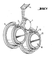
- the typical device shown in Figure 1 includes three wheels. Wheels 2 and 3 are the fiberizing wheels.
- the wheel 1 is a distribution wheel.
- the material to be fiberized flows from a chute 4, onto the distribution wheel 1. In contact with this wheel, it is accelerated and returned to the wheel 2 rotating in the opposite direction to the distribution wheel. From the wheel 2_, the material which does not adhere sufficiently is projected onto the wheel 3.
- the material adhering to the wheel is further accelerated until, under the effect of centrifugal force, it detaches and forms filaments which are projected into a gaseous current surrounding the wheel, and which carries them towards the receiving member, not shown.
- the gas stream is generated from the orifices arranged on the blowing ring 5. This ring produces the gas stream only in the areas where the fibers detach from the fiberizing wheels.
- the device of FIG. 1 comprises three wheels, there are also commonly found devices with 4 wheels or with 2 wheels operating on the same principle.
- the de.projection member of the treatment composition surrounded by a flange 32 is shown diagrammatically at 10.
- the treatment composition escapes through the slot 22 disposed on the face of this member.
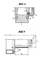
- FIG 2 In Figure 2 are shown the elements of the device directly involved in the fiberizing process: the wheel itself formed by the rim 7 supported by two flanges 8 and 9 and carried by the shaft 6, the projection member 10 of the fiber treatment composition, also consisting of two flanges 11 and 12. To these mobile elements must be added the blowing member 13 which is fixed, and generally integral with the frame, not shown.
- FIGS. 3 and 4 The detail of an example of the mounting of the elements on the shaft 6 is given in FIGS. 3 and 4.
- the flange 8 is brought against the stop 17 of the shaft 6.
- Each flange 8 and 9 has at its periphery a projection 14 and 15 which engages in the corresponding housing of the rim.
- the end of the hub 16 of the flange 11 of the projection member is housed in a recess of the flange 9.
- the hub 16 is screwed in cantilever at the threaded end 18 of the shaft 6, tightening the two flanges 8 and 9 on the rim 7.
- the locking of the wheel and body assembly projection is obtained by means of screws 19, the end of which is housed in the shaft 6. For the sake of clarity, only one screw is shown.
- the dimensions of the screw through holes in the different flanges and the dimensions of the screws are adjusted so that in practice the different fluids used in the device cannot flow from one compartment to another. However, it is not necessary to seal these various compartments. In fact, the coolant, or the treatment composition, after they have left the axial duct, follow a path controlled by the centrifugation movement.
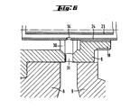
- FIG. 7 The method of assembling the parts constituting the projection member and the cooling water supply and treatment composition pipes is illustrated in FIG. 7.
- the fixing screws 19 do not are not shown.
- the attachment of the flange 12 to the flange 11 is obtained for example by means of screws arranged at the level of the flap 20.
- the two flanges 11 and 12 thus define a compartment 21 in which the treatment composition can circulate. This compartment opens outwards through the continuous slot 22 delimited by the two flanges.
- the treatment composition flows from the compartment 21 towards the slot 22 through a series of grooves formed radially in the flat 20.
- the size and distribution of the grooves connecting the compartment 21 and the slot 22 are such that they allow a uniform distribution of the composition over the entire periphery of the projection member.
- Figure 7 shows a section of the flanges 11 and 12 at the level of the flat. The cut of the figure is made at a groove in this flat.
- Line 23 leads the treatment composition into the compartment 21. It is placed inside the line 24 which contains the water. wheel cooling.
- the two pipes are joined by means of an annular plug 25 which closes the end of the pipe 24. This plug can be screwed or fixed in any other similar analogous manner.
- a seal 28 is held tight against the bearing 26 by the shoulder 29 of the hub 16.
- the circulation of the cooling water is carried out successively by the pipe 24 and by means of openings 34 made in this pipe, (only one opening is shown) inside the shaft. 6, and more precisely in a groove 30 formed on the wall of the shaft.
- the groove 30 aims to direct the water towards one or more openings 31 located at the bottom of this groove.
- the openings 31 are arranged so that the water flows between the flanges 8 and 9 of the wheel.
- the openings 31 are offset relative to the holes of the screws 19.
- the cooling water After contact with the rim 7, the cooling water is discharged (possibly in the form of vapor) through openings, not shown, arranged on the sides of the wheel.
- FIG. 8 An alternative embodiment of the projection member is shown diagrammatically in FIG. 8.
- This variant is substantially different from the previous modes in that the composition leaving the pipe located in the axis of the shaft is not maintained in a confined space. It is applied to a disc 33 of conical shape whose concavity is turned towards the fiberizing wheel, the composition progresses along the "internal" face of the disc, from the point where it is applied. The taper maintains the composition plated on the disc up to the periphery thereof.
- FIG. 4 shows an embodiment of a protection element for the projection disk 10.
- This element is here a flange 32.
- the flange is fixed to the flange 9 of the fiberizing wheel. It partially envelops the disk 10.
- the rim of the disk from which the drops of composition stand out, of course, is not enveloped.
- the rim of the wheel is shown with a flat outer surface, for the convenience of the drawing. In fact, in practice, to facilitate "hanging" of the material to be fiberized, this surface is normally provided with longitudinal grooves.
- a fiberizing apparatus comprising three wheels arranged as shown in FIG. 1.
- the diameters of the wheels and their rotation speeds are respectively:
- the width (l R ) of the surface of the fiberizing wheels is 85 mm (the surface is grooved longitudinally).
- the blowing member envelops the wheels as shown in FIG. 1. It comprises a series of orifices, 405 in total, the opening diameter of which is 2 mm. The spacing between two consecutive holes is 6 mm. These holes are at a radial distance from the wheel y RJ of 30 mm and axial x RJ of 10 mm.
- the steam used is at a pressure of approximately 3.5 ⁇ 10 5 Pa.
- the complete appliance blows approximately 2.5 tonnes / hour of steam.
- the projection of binder is carried out on the two fiberizing wheels by devices as shown in FIG. 7.
- the diameter of the centrifuge discs is 320 mm.
- An aqueous binder composition based on formo-phenolic resol is sprayed.
- the fiber material is a glass of melilite.
- the feed rate is approximately 3 tonnes / hour.
- a 50 mm thick fiber mat is formed, the thermal conductivity of which at 23.9 ° C is 38.2 mW / m. ° C.
- fiberizing is carried out under similar conditions by spraying the binder on the fibers upstream of the wheel.
- the blowing ramp has only 33 orifices, 16 of which are used for spraying the binder.
- the diameter of the orifices is 3 mm. They are arranged at a radial distance y RJ of 120 to 150 mm.
- the binder supply holes have a diameter of 2 mm.
- the steam pressure in the boom is 3 to 4.10 5 Pa.
- the steam consumption is 1.2 tonnes / hour.
- the fiber mat obtained has the same insulating characteristics but its mechanical properties are less good, as indicated in the following table.
- the product obtained according to the invention has a significant improvement in tensile strength, which characterizes the "cohesion" of the mattress, and a lower rate of sagging under pressure.
- the invention therefore makes it possible to improve the operating conditions of the fiber-drawing techniques of the type under consideration while maintaining or even improving the qualities of the products obtained.
- the mode of spraying the treatment composition according to the invention is also remarkable for its flexibility of use. It allows in particular to project compositions of varied nature with the same ease.
- the viscosity of linseed oil is much higher than that of formo-phenolic resins and in the products bound to linseed oil the proportion of binder is usually lower. These two aspects, lower viscosity and higher amount are the ten - dance to clogging of spray orifices is increased considerably, so that this type of binder is rarely used.
- the particularities of the compositions based on linseed oil raised no difficulty. Centrifugation takes place regularly and the fibers are coated very satisfactorily.
- the self-cleaning nature of the device appeared to be particularly advantageous.
- the transition from one composition to another can be carried out almost instantaneously and without the need for a prior purging operation.
Abstract
Description
L'invention concerne des perfectionnements apportés aux techniques de fibrage centrifuge dans lesquelles le matériau à fibrer est conduit à l'état fondu de l'extérieur à la périphérie de roues de fibrage, est entrainé par ces roues et s'en détache sous forme de fibres sous l'effet de la force centrifuge. Ces techniques font partie de celles que l'on dit à centrifugation "libre", par opposition aux techniques dans lesquelles l'organe de centrifugation joue en plus le rôle de filière.The invention relates to improvements made to centrifugal fiberizing techniques in which the material to be fiberized is led in the molten state from the outside to the periphery of fiberizing wheels, is driven by these wheels and detaches from them in the form of fibers under the effect of centrifugal force. These techniques are part of those which are said to be "free" centrifugation, as opposed to techniques in which the centrifuge member also plays the role of a die.
Dans ces techniques, on utilise en général plusieurs roues de fibrage disposées à proximité les unes des autres. Le matériau passe d'une roue à l'autre, chaque roue transformant en fibre une partie du matériau reçu, et renvoyant l'excédent sur la roue suivante.In these techniques, several fiberizing wheels are generally used which are arranged close to one another. The material passes from one wheel to another, each wheel transforming part of the material received into fiber, and returning the excess to the next wheel.
La production de fibres par centrifugation n'est pas limitée à ces techniques. Il est également connu de conduire la matière à fibrer sur la face d'un disque ou d'une assiette en rotation, ou encore d'utiliser un tambour dont la périphérie est percée de multiples orifices formant filière et d'où la matière s'échappe sous l'effet de la force centrifuge.The production of fibers by centrifugation is not limited to these techniques. It is also known to conduct the material to be fiberized on the face of a rotating disc or plate, or even to use a drum whose periphery is pierced with multiple orifices forming a die and from which the material s' escapes under the effect of centrifugal force.
Ces deux derniers types de procédés se distinguent de ceux auxquels l'invention se rattache, aussi bien par les moyens employés que par les résultats qu'ils permettent d'atteindre. Ainsi la centrifugation au moyen d'un disque ne conduit pas en pratique à des fibres suffisamment fines pour de nombreuses applications, par ailleurs, l'utilisation de certains matériaux traditionnels dans ce genre de fabrication est impossible dans un tambour formant filière en raison par exemple d'une température de traitement trop élevée ou de la présence de défauts d'homogénéité du matériau.These last two types of process are distinguished from those to which the invention relates, both by the means employed and by the results which they make it possible to achieve. Thus centrifugation by means of a disc does not lead in practice to fibers sufficiently fine for many applications, moreover, the use of certain traditional materials in this kind of manufacture is impossible in a drum forming die due for example too high a processing temperature or the presence of material homogeneity defects.
Vis-à-vis de ces autres techniques, celles dans lesquelles on procède au fibrage en déposant le matériau de l'extérieur sur la surface périphérique de la façon rappelée ci-dessus présentent donc certains avantages. Mais pour d'autres caractéristiques, ce type de fibrage ne donne pas entièrement satisfaction en dépit des nombreuses améliorations qui ont été proposées jusqu'à présent.With respect to these other techniques, those in which fiberizing is carried out by depositing the material from the outside on the peripheral surface in the manner recalled above therefore have certain advantages. But for other characteristics, this type of fiberizing does not not entirely satisfactory despite the many improvements that have been proposed so far.
Le but de l'invention est de permettre la mise en oeuvre de ce type de fibrage dans des conditions plus satisfaisantes. En particulier l'invention se propose de donner à l'utilisateur. des moyens pour mieux conduire la formation et le traitement des fibres. Un autre but de l'invention est d'accroitre le rendement en fibre, c'est-à-dire la proportion du matériau récupéré sous forme de fibres par rapport à l'ensemble du matériau utilisé. On sait en effet qu'une des difficultés permanentes de ce type de technique est la présence d'une quantité relativement importante de produits infibrés. Un autre but de l'invention est d'améliorer les qualités des produits préparés, notamment les propriétés mécaniques et les propriétés isolantes. Un autre but de l'invention est de faciliter le fonctionnement continu des installations en réduisant la fréquence et la durée des arrêts occasionnés par les remises en état périodiques.The object of the invention is to allow the implementation of this type of fiberizing under more satisfactory conditions. In particular, the invention proposes to give to the user. means to better conduct the formation and treatment of fibers. Another object of the invention is to increase the fiber yield, that is to say the proportion of the material recovered in the form of fibers relative to all of the material used. It is known that one of the permanent difficulties of this type of technique is the presence of a relatively large quantity of fiber-containing products. Another object of the invention is to improve the qualities of the products prepared, in particular the mechanical properties and the insulating properties. Another object of the invention is to facilitate the continuous operation of the installations by reducing the frequency and the duration of the stoppages caused by the periodic overhauls.
En raison des très nombreux facteurs entrant en jeu dans les mécanismes conduisant à la formation de la fibre puis à celle du produit final, ces techniques se prêtent difficilement à une analyse systématique. Ceci explique en partie la diversité des solutions antérieures proposées pour parvenir à ce genre d'améliorations.Because of the very many factors involved in the mechanisms leading to the formation of the fiber and then that of the final product, these techniques are difficult to lend to systematic analysis. This partly explains the diversity of previous solutions proposed to achieve this kind of improvement.
Les premières études de ces systèmes se sont efforcées de déterminer les meilleures conditions de centrifugation : mode d'introduction du matériau à fibrer, forme de la surface des roues, vitesse de rotation, dimensions, position relative et nombre des roues, etc...The first studies of these systems endeavored to determine the best centrifugation conditions: mode of introduction of the material to be fiberized, shape of the surface of the wheels, speed of rotation, dimensions, relative position and number of the wheels, etc.
Ultérieurement, l'accent a été mis sur les conditions dans lesquelles les fibres, se détachant des roues de fibrage, sont traitées et transportées jusqu'à l'endroit où elles sont collectées.Subsequently, emphasis was placed on the conditions under which the fibers, coming loose from the fiberizing wheels, are processed and transported to the place where they are collected.
Ainsi il a été envisagé de soumettre les fibres au moment de leur formation à un courant gazeux qui les entraine et les sépare des particules infibrées.Thus, it has been envisaged to subject the fibers at the time of their formation to a gas stream which entrains them and separates them from the infibrated particles.
Pour améliorer ces techniques, diverses propositions ont été également faites en ce qui concerne le traitement des fibres pour leur utilisation sous forme de matelas isolants. De façon générale, pour ces utilisations, les fibres sont enduites par pulvérisation d'une composition liquide de liants, destinés après séchage et/ou traitement thermique à conférer sa cohésion et ses propriétés mécaniques au produit final.To improve these techniques, various proposals have also been made with regard to the treatment of fibers for their use in the form of insulating blankets. In general, for these uses, the fibers are coated by spraying with a liquid composition of binders, intended after drying and / or heat treatment to impart its cohesion and its mechanical properties to the final product.
Ce traitement pour être satisfaisant ne doit bien évidemment pas perturber l'opération de fibrage proprement dite. Il doit également conduire à une enduction des fibres aussi homogène que possible.To be satisfactory, this treatment must obviously not not disturb the fiber drawing operation itself. It must also lead to a coating of the fibers as homogeneous as possible.
Dans un mode de réalisation traditionnel, la pulvérisation est effectuée sur le trajet du courant gazeux portant les fibres vers la surface collectrice, ceci à distance .des roues de fibrage. Cette façon de faire ne permet pas d'obtenir une bonne homogénéité de l'enduction. La raison exacte n'en est pas connue mais on peut remarquer que l'écoulement du courant gazeux conduit les fibres de façon très irrégulière devant l'organe de pulvérisation. Par ailleurs, il est d'autant plus difficile d'enduire correctement toutes les fibres que celles-ci ont tendance à se rassembler en paquets ou mèches, au cours de leur progression vers l'organe collecteur.In a traditional embodiment, the spraying is carried out on the path of the gas stream carrying the fibers towards the collecting surface, this at a distance from the fiberizing wheels. This procedure does not allow good homogeneity of the coating to be obtained. The exact reason is not known but it can be noted that the flow of the gas stream leads the fibers very irregularly in front of the spraying member. Furthermore, it is all the more difficult to properly coat all the fibers as these tend to collect in bundles or wicks, during their progression towards the collecting member.
Pour tenter d'améliorer cette enduction, il a été proposé de projeter la composition pulvérisée sur la trajet des fibres au-delà des roues de fibrage avec la même vitesse et dans la même direction que celles du courant gazeux portant les fibres. Il ne semble pas que ces mesures aient permis d'améliorer les résultats de façon pleinement satisfaisante.In an attempt to improve this coating, it has been proposed to project the sprayed composition onto the path of the fibers beyond the fiberizing wheels with the same speed and in the same direction as those of the gas stream carrying the fibers. These measures do not seem to have resulted in a fully satisfactory improvement of the results.
Pour éviter les difficultés précédentes, il a été proposé, et ceci constitue également un mode traditionnel, de pulvériser la composition de traitement au voisinage des roues de fibrage, éventuellement dans le courant gazeux et destiné à entraîner les fibres et les séparer des particules infibrées. Dans ce dernier cas la pulvérisation est faite dans ces gaz avant qu'ils n'entrent au contact avec les fibres.To avoid the above difficulties, it has been proposed, and this also constitutes a traditional method, to spray the treatment composition in the vicinity of the fiberizing wheels, possibly in the gas stream and intended to entrain the fibers and separate them from the infibrated particles. In the latter case the spraying is done in these gases before they come into contact with the fibers.
En opérant de cette façon, les fibres sont mises au contact de la composition de traitement dès leur formation, dans des conditions mieux contrôlées. Néanmoins, ce mode d'enduction comporte certains inconvénients.By operating in this way, the fibers are brought into contact with the treatment composition as soon as they are formed, under better controlled conditions. However, this coating method has certain drawbacks.
Un de ceux-ci provient de la présence des organes de pulvérisation à proximité de la surface de la roue. Dans cette position, ces organes sont exposés à la chaleur rayonnant depuis la surface portée à haute température par le contact avec le matériau fondu. Ils sont aussi exposés aux projections accidentelles de matériau fondu. Mais surtout ces organes de pulvérisation ont tendance à retenir les fibres échappées du courant qui les conduit vers la surface de réception. Ces fibres enduites de composition habituellement sensible à la chaleur subissent alors une "cuisson". Il se forme ainsi sur l'organe de pulvérisation des dépôts aboutissant rapidement à l'obstruction de cet organe.One of these stems from the presence of the spraying members near the surface of the wheel. In this position, these organs are exposed to radiant heat from the surface brought to high temperature by contact with the molten material. They are also exposed to accidental splashes of molten material. But above all these spraying members tend to retain the fibers escaped from the current which leads them to the receiving surface. These coated fibers of composition usually sensitive to heat then undergo a "cooking". There is thus formed on the spraying member deposits quickly leading to the obstruction of this member.
Pour minimiser ces inconvénients, on peut utiliser des buses dont les orifices sont relativement grands, ce qui pour un débit donné conduit à réduire le nombre de buses. En définitive ces buses, moins nombreuses, sont plus espacées les unes des autres et il en résulte une moins bonne homogénéité du traitement, préjudiciable. à la qualité du produit final.To minimize these drawbacks, nozzles with relatively large orifices can be used, which for a given flow rate results in a reduction in the number of nozzles. Ultimately these fewer nozzles are more spaced from each other and this results in a less homogeneous treatment, which is detrimental. the quality of the final product.
Par ailleurs, quelles que soient les précautions prises, on n'évite pas complètement l'encrassage progressif qui conduit au bouchage des buses de pulvérisation, et les interventions pour remise en état occasionnent des arrêts de production relativement fréquents.In addition, whatever precautions are taken, progressive fouling which leads to clogging of the spray nozzles is not completely avoided, and interventions for reconditioning cause relatively frequent production stoppages.
Dans les dispositifs comportant plusieurs roues de fibrage, il apparait préférable du point de vue de la circulation de la matière d'une roue à l'autre, d'éviter le soufflage et/ou la pulvérisation entre les roues, en particulier pour ne pas refroidir le matériau non encore fibré. On s'efforce en général de faire en sorte que les fibres se forment en dehors de ces zones comprises entre les roues. Cependant, une certaine quantité de fibres, qu'elle se forme ou soit entrainée, passe dans ces zones et n'est pas directement touchée par la composition pulvérisée ce qui accroit le risque de défaut d'homogénéité.In devices comprising several fiberizing wheels, it appears preferable from the point of view of the circulation of the material from one wheel to another, to avoid blowing and / or spraying between the wheels, in particular so as not to cool the material not yet fiberized. In general, efforts are made to ensure that the fibers form outside of these zones comprised between the wheels. However, a certain quantity of fibers, whether formed or entrained, passes through these areas and is not directly affected by the sprayed composition, which increases the risk of lack of homogeneity.
L'amélioration de l'enduction des fibres, en présence ou non de mèches, et par suite l'amélioration des qualités du produit final sont parmi les avantages procurés par l'invention qui concerne un procédé de formation d'un matelas de fibres. Dans ce procédé, le matériau destiné à former les fibres est conduit à l'état étirable sur la surface périphérique d'une roue de centrifugation. Une partie au moins de ce matériau est projetée sous forme de fibres dans une direction radiale par rapport à la roue. Les fibres qui se forment sont entraînées en nappe par un courant gazeux dirigé transversalement au sens de projection des fibres hors de la roue. Le courant gazeux portant les fibres déviées de leur trajectoire initiale est mis au contact d'une composition de traitement liquide à l'état finement divisé.Improving the coating of fibers, whether or not wicks are present, and consequently improving the qualities of the final product are among the advantages provided by the invention which relates to a process for forming a fiber mat. In this process, the material intended to form the fibers is led in the stretchable state on the peripheral surface of a centrifuge wheel. At least part of this material is projected in the form of fibers in a radial direction relative to the wheel. The fibers which form are entrained in the form of a gas current directed transversely to the direction of projection of the fibers out of the wheel. The gas stream carrying the fibers deviated from their initial trajectory is brought into contact with a liquid treatment composition in the finely divided state.
Dans le procédé selon l'invention la composition liquide est projetée sous forme de gouttelettes dans le courant gazeux portant les fibres, transversalement à celui-ci, par centrifugation depuis la zone située à l'intérieur de la nappe de fibres et à proximité immédiate de la roue de fibrage, et les gouttelettes entrant dans le courant gazeux sont finement divisées par celui-ci.In the process according to the invention, the liquid composition is sprayed in the form of droplets into the gas stream carrying the fibers, transverse thereto, by centrifugation from the zone located inside the sheet of fibers and in the immediate vicinity of the fiberizing wheel, and the droplets entering the gas stream are finely divided by it.
Selon l'invention, l'énergie qu'il faut communiquer à la composition liquide provient essentiellement de la rotation d'un organe mécanique sur ou dans lequel elle est conduite, qui l'entraîne et dont elle s'échappe sous l'effet de la force centrifuge. C'est dans ce sens qu'il s'agit d'une projection par centrifugation. L'énergie des gouttelettes doit être suffisante pour leur permettre d'atteindre ce courant et d'y pénétrer.According to the invention, the energy which must be communicated to the liquid composition comes essentially from the rotation of an organ mechanical on or in which it is driven, which drives it and from which it escapes under the effect of centrifugal force. It is in this sense that it is a projection by centrifugation. The energy of the droplets must be sufficient to allow them to reach and penetrate this current.
La zone située à l'intérieur de la nappe de fibres est celle qui se trouve en aval de la roue de fibrage (dans le sens du courant entraînant les fibres), et est au moins partiellement enveloppée par cette nappe. Il faut remarquer que selon l'invention, la projection n'étant pas limitée à un secteur particulier de la roue, toutes les fibres, même celles qui se présenteraient entre les roues, seraient soumises au traitement.The zone located inside the fiber sheet is that which is downstream of the fiberizing wheel (in the direction of the current driving the fibers), and is at least partially enveloped by this sheet. It should be noted that according to the invention, the projection not being limited to a particular sector of the wheel, all the fibers, even those which would appear between the wheels, would be subjected to the treatment.
La nappe de fibre et le courant gazeux qui la porte sont habituellement orientés suivant une direction peu inclinée par rapport à l'axe de rotation de la roue, notamment pour permettre une évacuation commode des fibres. De préférence la direction du courant gazeux est parallèle à l'axe de la roue.The fiber sheet and the gaseous current which carries it are usually oriented in a direction which is not very inclined relative to the axis of rotation of the wheel, in particular to allow a convenient evacuation of the fibers. Preferably the direction of the gas stream is parallel to the axis of the wheel.
Pour des raisons de simplicité d'exécution, la centrifugation de la composition liquide est avantageusement réalisée à partir d'un organe coaxial à la roue. Les gouttelettes de composition sont donc projetées suivant une direction sensiblement normale à l'axe de rotation et au courant gazeux portant les fibres.For reasons of simplicity of execution, the centrifugation of the liquid composition is advantageously carried out from a member coaxial with the wheel. The composition droplets are therefore projected in a direction substantially normal to the axis of rotation and to the gas stream carrying the fibers.
La projection de la composition de traitement est avantageusement effectuée aussi près que possible de la roue de fibrage.The spraying of the treatment composition is advantageously carried out as close as possible to the fiberizing wheel.
Dans la pratique la projection de la composition de traitement est réalisée suffisamment près de la roue de fibrage pour que les gouttelettes rencontrent le courant gazeux portant les fibres en un point où son écoulement n'est pas encore perturbé par le mélange avec l'air induit. Bien entendu, le désordre dans l'écoulement occasionné par ce mélange va en s'accroissant au fur et à mesure que l'on s'éloigne de la roue. Il n'y a pas à proprement parler de limite stricte, mais plus la projection de composition est opérée près de la roue, d'une part plus intense est l'action du courant gazeux sur les gouttes de composition, et d'autre part meilleure est l'homogénéité de la distribution des particules de composition au sein du courant gazeux portant les fibres (notamment en raison de ce que les dimensions utiles du courant, à ce point de sa progression, sont relativement limitées).In practice, the spraying of the treatment composition is carried out close enough to the fiberizing wheel so that the droplets meet the gas current carrying the fibers at a point where its flow is not yet disturbed by the mixture with the induced air. . Of course, the disorder in the flow caused by this mixture increases as one moves away from the wheel. Strictly speaking, there is no strict limit, but the closer the projection of composition is made to the wheel, on the one hand more intense is the action of the gas current on the drops of composition, and on the other hand better is the homogeneity of the distribution of the particles of composition within the gas stream carrying the fibers (in particular because the useful dimensions of the stream, at this point of its progression, are relatively limited).
Dans des modes de réalisation avantageux, la distance séparant le bord aval de la roue de centrifugation du plan dans lequel la projection de la composition de traitement est réalisée ne dépasse pas 150 mm, et de préférence est inférieure à 60 mm.In advantageous embodiments, the distance separating the downstream edge of the centrifuge wheel from the plane in which the projection of the treatment composition is carried out does not exceed 150 mm, and preferably is less than 60 mm.
Si cela apparait nécessaire compte tenu de l'appareillage et/ou des conditions opératoires, un minimum de distance entre le bord aval de la roue et l'organe de projection peut être maintenu pour éviter, par exemple, que les transferts de chaleur ne perturbent le fonctionnement de l'organe de projection de la composition de traitement.If this appears necessary taking into account the apparatus and / or the operating conditions, a minimum distance between the downstream edge of the wheel and the projection member can be maintained to avoid, for example, that heat transfers do not disturb the operation of the projection member of the treatment composition.
L'organe de centrifugation libère la composition de traitement à une distance de l'axe de rotation telle que les gouttes qui s'échappent aient acquis une énergie suffisante pour atteindre le courant gazeux portant les fibres. Plus petite est la distance séparant le point où les gouttes se détachent de l'organe de projection du courant gazeux, plus l'énergie conférée est grande. En outre, la localisation du point de rencontre des gouttes avec le courant gazeux est d'autant mieux assurée que la distance parcourue par les gouttes sans le support de cet organe de projection est plus courte. S'il parait donc avantageux de réduire cette distance, il faut néanmoins ménager un certain espace entre le courant gazeux et l'extrémité de l'organe de projection pour éviter de perturber la trajectoire des fibres ou pour éviter de soumettre cet organe aux particules de matériau fondu qui, débordant la surface de la roue, viendraient le frapper accidentellement.The centrifuge member releases the treatment composition at a distance from the axis of rotation such that the escaping drops have acquired sufficient energy to reach the gas stream carrying the fibers. The smaller the distance between the point where the drops detach from the projection member of the gas stream, the greater the energy imparted. In addition, the location of the meeting point of the drops with the gas stream is all the better ensured the shorter the distance traveled by the drops without the support of this projection member. If it therefore seems advantageous to reduce this distance, it is nevertheless necessary to provide a certain space between the gas stream and the end of the projection member to avoid disturbing the path of the fibers or to avoid subjecting this member to particles of molten material which, beyond the surface of the wheel, would accidentally strike it.
La vitesse radiale à communiquer à la composition, à la périphérie de l'organe de projection, peut varier en fonction. de nombreux facteurs : dimension des gouttes, distance du courant gazeux, vitesse du courant gazeux ... Compte tenu des paramètres de dimension de l'appareillage dont il est donné des exemples dans la suite de la description et également des caractéristiques du courant gazeux, des vitesses avantageuses se situent entre 50 et 120 m/s et de préférence entre 70 et 100 m/s.The radial speed to be communicated to the composition, at the periphery of the projection member, can vary as a function. many factors: size of the drops, distance from the gas stream, speed of the gas stream, etc. Given the parameters of the size of the apparatus, examples of which are given in the description below and also the characteristics of the gas stream, advantageous speeds are between 50 and 120 m / s and preferably between 70 and 100 m / s.
Un avantage lié au fait que la composition est projetée par centrifugation est d'éviter de perturber l'écoulement normal du courant gazeux portant les fibres par un jet gazeux en aval de la roue de fibrage comme c'est le cas lorsque l'on pulvérise au moyen d'un fluide propulseur. L'impact des gouttes de composition sur l'écoulement du courant gazeux est sensiblement moindre que celui du jet de pulvérisation. On réduit ainsi le risque d'apparition de tourbillons et les inconvénients que l'on a dit, notamment en ce qui concerne l'enduction des mèches de fibres.An advantage linked to the fact that the composition is sprayed by centrifugation is to avoid disturbing the normal flow of the gaseous current carrying the fibers by a gas jet downstream of the fiberizing wheel as is the case when spraying by means of a propellant fluid. The impact of the drops of composition on the flow of the gas stream is significantly less than that of the spray jet. This reduces the risk of the appearance of vortices and the disadvantages that have been said, in particular as regards the coating of the strands of fibers.
Dans ce qui précède on a indiqué que la projection se faisait par centrifugation. Il va de soi que si la centrifugation est le moyen principal, il peut être associé à d'autres moyens. Ainsi, normalement la composition de traitement est envoyée à l'organe de projection sous une pression qui ne dépasse pas celle permettant sa progression jusqu'à cet organe. Il est possible néanmoins d'envoyer la composition sous une pression plus forte. On peut aussi le cas échéant associer l'utilisation de l'organe de centrifugation à celle d'un fluide propulseur dans la mesure où ce dernier ne perturbe pas la formation ou le transport des fibres, ou encore la constitution du produit final.In the above it was indicated that the projection was done by centrifugation. It goes without saying that if centrifugation is the main means, it can be combined with other means. Thus, normally the treatment composition is sent to the spraying member under a pressure which does not exceed that allowing its progression to this member. It is nevertheless possible to send the composition under higher pressure. It is also possible, if necessary, to associate the use of the centrifuge member with that of a propellant fluid insofar as the latter does not disturb the formation or the transport of the fibers, or even the constitution of the final product.
Il est remarquable de constater que selon l'invention, contrairement à ce qui avait été envisagé antérieurement, il n'est pas nécessaire d'opérer une dispersion très fine de la composition de traitement au niveau de l'organe de projection pour avoir une bonne enduction des fibres. Pour faciliter la projection et la pénétration des gouttes dans le courant gazeux, il peut même être préférable que ces gouttes soient de dimensions relativement importantes. Ceci est rendu possible par le fait que la dispersion de ces gouttes s'achève dans et sous l'action du courant gazeux.It is remarkable to note that according to the invention, contrary to what had been envisaged previously, it is not necessary to operate a very fine dispersion of the treatment composition at the level of the projection member to have good coating of fibers. To facilitate the projection and penetration of the drops into the gas stream, it may even be preferable for these drops to be of relatively large dimensions. This is made possible by the fact that the dispersion of these drops ends in and under the action of the gas stream.
En effet, l'introduction de la composition dans le courant gazeux, à proximité de la zone de fibrage, c'est-à-dire en un point où le courant gazeux présente un maximum de vitesse et d'énergie favorise l'éclatement des gouttes et d'autant plus qu'elles sont plus volumineuses.Indeed, the introduction of the composition into the gas stream, near the fiberizing zone, that is to say at a point where the gas stream has a maximum speed and energy promotes the bursting of the drops and especially since they are more voluminous.
L'éclatement des gouttes de composition dans le courant gazeux portant les fibres est une caractéristique particulièrement avantageuse de l'invention. On obtient de cette façon une composition aussi finement divisée qu'au moyen d'une pulvérisation sans en avoir les inconvénients indiqués précédemment, à savoir, soit la difficulté de faire pénétrer l'aérosol dans le courant gazeux à grande vitesse, soit la présence de buses de pulvérisation dans une position préjudiciable à leur bon fonctionnement. En effet d'une part les gouttes centrifugées pénètrent plus aisément dans le courant gazeux qu'un aérosol, et d'autre part, en raison même de son mode de fonctionnement, l'organe de centrifugation présente un caractère que l'on peut qualifier d"'auto- décrassant" (ceci notamment dans le cas où la composition projetée assure un refroidissement de l'organe de projection et évite ainsi le collage des fibres)_.The bursting of the drops of composition in the gas stream carrying the fibers is a particularly advantageous characteristic of the invention. In this way a composition is obtained which is as finely divided as by spraying without having the drawbacks indicated above, namely, either the difficulty of making the aerosol penetrate into the gas stream at high speed, or the presence of spray nozzles in a position prejudicial to their proper functioning. Indeed, on the one hand, the centrifuged drops penetrate more easily into the gas stream than an aerosol, and on the other hand, because of its very mode of operation, the centrifuge member has a character which can be qualified. of "self-cleaning" (this in particular in the case where the projected composition ensures cooling of the projection member and thus avoids the sticking of the fibers).
Un autre avantage de la modification des gouttes dans le courant est lié à la façon dont s'effectue cette modification. L'étude du comportement d'une goutte projetée dans un courant gazeux intense montre que l'éclatement en multiples particules est l'aboutissement d'une série de déformations au cours desquelles la goutte "déformée" voit ses dimensions considérablement accrues. Ces déformations, peuvent prendre plusieurs formes et notamment celle d'une bulle de grande dimension. Ce processus de déformation non seulement prépare l'éclatement mais en outre, compte tenu de l'accroissement des dimensions, augmente la probabilité de rencontre avec les fibres.Another benefit of changing the drops in the neck rant is related to how this change is made. The study of the behavior of a drop projected in an intense gas current shows that the bursting into multiple particles is the result of a series of deformations during which the drop "deformed" sees its dimensions considerably increased. These deformations can take several forms, in particular that of a large bubble. This deformation process not only prepares the burst but also, given the increase in dimensions, increases the probability of meeting with the fibers.
De façon générale, quels que soient les phénomènes auxquels sont soumises les gouttes, il en résulte une bonne homogénéité de leur dispersion dans le courant gazeux et par suite une bonne répartition de la composition sur le produit récupéré sur la surface collectrice.In general, whatever the phenomena to which the drops are subjected, the result is good homogeneity of their dispersion in the gas stream and consequently a good distribution of the composition on the product recovered on the collecting surface.
Dans la pratique, beaucoup des paramètres qui déterminent les conditions dans lequelles les gouttes sont projetées, entrent dans le courant gazeux, et sont divisées, sont fixés en fonction des conditions de fibrage. C'est le cas notamment de la vitesse de rotation de la roue lorsque l'organe de projection est solidaire de celle-ci. C'est le cas aussi dans une certaine mesure des caractéristiques du courant gazeux. L'expérimentateur dispose néanmoins de certains moyens pour intervenir de façon spécifique sur la détermination des caractéristiques des gout- _.tes de composition. Il s'agit essentiellement de la position de l'organe de projection, de sa géométrie et notamment de la distance à l'axe de rotation du point d'où s'échappent les goutes. Il est aussi possible de modifier les orifices de l'organe de projection ou le cheminement de la composition dans cet organe.In practice, many of the parameters that determine the conditions under which the drops are sprayed, enter the gas stream, and are divided, are set according to the fiberizing conditions. This is particularly the case with the speed of rotation of the wheel when the projection member is integral with the latter. This is also to some extent the characteristics of the gas stream. The experimenter nevertheless has certain means to intervene specifically in determining the characteristics of the drops of composition. This is essentially the position of the projection member, its geometry and in particular the distance to the axis of rotation of the point from which the drops escape. It is also possible to modify the orifices of the projection member or the path of the composition in this member.
Dans les conditions préférées de vitesse de rotation et de soufflage qui sont données à titre d'exemple dans la description, on peut être conduit à. projeter des gouttes dont les dimensions moyennes sont plus de 10 fois celles des aérosols traditionnellement utilisés et reconnus pour permettre une bonne distribution. A titre indicatif, dans une composition aqueuse de liant pulvérisée de façon traditionnelle sur des fibres minérales, 90 % des gouttelettes ont une dimension moyenne de l'ordre de 30 . Lorsque selon l'invention la composition est projetée par centrifugation les gouttes formées de façon typique ont des dimensions comprises entre 40 et 500 , et une dimension moyenne de l'ordre de 250 .Under the preferred conditions of rotation speed and blowing which are given by way of example in the description, it may be necessary to. spray drops whose average dimensions are more than 10 times those of aerosols traditionally used and recognized to allow a good distribution. As an indication, in an aqueous binder composition sprayed in the traditional way on mineral fibers, 90% of the droplets have an average size of the order of 30. When, according to the invention, the composition is sprayed on by centrifugation, the drops typically formed have dimensions between 40 and 500, and an average dimension of the order of 250.
Suivant une autre caractéristique de l'invention, il est apparu avantageux de faire en sorte que le courant gazeux ait une vitesse élevée dans la zone où il rencontre la composition projetée.According to another characteristic of the invention, it appeared advantageous to ensure that the gas stream has a speed high in the area where it meets the intended composition.
Comme indiqué ci-dessus, l'utilisation d'un courant gazeux rapide est favorable à la dispersion de la composition de traitement en facilitant l'éclatement des gouttes.As indicated above, the use of a rapid gas stream is favorable to the dispersion of the treatment composition by facilitating the bursting of the drops.
Par ailleurs, le choix d'un courant gazeux.à vitesse élevée pourrait avoir une influence favorable sur le taux de fibrage et même sur les qualités du produit final.Furthermore, the choice of a gaseous stream at high speed could have a favorable influence on the fiber drawing rate and even on the qualities of the final product.
Les raisons précises de ces améliorations ne sont pas parfaitement élucidées. En ce qui concerne l'amélioration du taux de fibrage, on peut penser qu'une certaine quantité de particules infibrées, ou insuffisamment fibrées, est étirée de façon complémentaire en pénétrant dans le courant gazeux, et d'autant mieux qu'il est plus rapide.The precise reasons for these improvements are not fully understood. With regard to the improvement of the fiber-drawing rate, it may be thought that a certain quantity of particles which are fiber-free, or insufficiently fiber-coated, is stretched in a complementary manner by penetrating into the gas stream, and all the better the more fast.
Pour le produit final on peut avancer l'hypothèse suivante.For the final product, the following hypothesis can be advanced.
En formant dans la zone de fibrage et d'enduction un courant gazeux rapide, on crée dans cette zone un écoulement qui entraîne les fibres en les maintenant dispersées. Les mouvements tourbillonnaires engendrés par le mélange du courant gazeux avec l'air ambiant induit, et que l'on suppose favoriser le développement des mèches, sont repoussés à distance de la roue de fibrage. La dispersion des gouttes et leur éclatement se développe dans un temps où les fibres sont bien individualisées. Dans le courant gazeux, le mélange particules de composition et fibres est par suite bien homogène, même s'il se forme des mèches dans la progression ultérieure vers la surface de réception. En outre en rejetant vers la surface de réception les phénomènes développant les mèches, on réduit le temps pendant lequel ce développement peut se produire et ainsi le nombre et la dimension des mèches.By forming a rapid gas stream in the fiberizing and coating area, a flow is created in this area which entrains the fibers while keeping them dispersed. The vortex movements generated by the mixture of the gaseous current with the induced ambient air, and which is supposed to favor the development of the wicks, are repelled at a distance from the fiberizing wheel. The dispersion of the drops and their bursting develops in a time when the fibers are well individualized. In the gas stream, the mixture of composition particles and fibers is consequently very homogeneous, even if wicks form in the subsequent progression towards the receiving surface. In addition, by rejecting the phenomena developing the wicks towards the reception surface, the time during which this development can occur is reduced, thereby reducing the number and size of the wicks.
Quel que soit le phénomène qui conduit à cette amélioration, il est certain que les conditions de soufflage de ce courant gazeux sont différentes de celles qui étaient réalisées antérieurement dans ces techniques de fibrage par centrifugation à partir de la surface périphérique d'une roue.Whatever the phenomenon which leads to this improvement, it is certain that the conditions for blowing this gas stream are different from those which were carried out previously in these fiber-drawing techniques by centrifugation from the peripheral surface of a wheel.
Dans ces techniques antérieures,le but du soufflage est essentiellement, comme on l'a indiqué, d'emporter les fibres vers la surface de réception et éventuellement d'opérer une séparation des infibrés, ce qui, dans les deux cas, peut être obtenu à des vitesses relativement faibles. L'opération de soufflage selon l'invention semble par contre intervenir sur les conditions dans lesquelles se forment les fibres. Contrairement à ce que l'on pouvait craindre antérieurement, l'accroissement de la vitesse des gaz de soufflage, dans les limites indiquées ci-après, ne perturbe pas la formation de la fibre et améliore la qualité du produit final.In these prior techniques, the purpose of blowing is essentially, as indicated, to carry the fibers towards the receiving surface and possibly to carry out a separation of the fibers, which, in both cases, can be obtained at relatively low speeds. The blowing operation according to the invention, on the other hand, seems to intervene in the conditions in which the fibers are formed. Contrary to what was feared previously, the increase in the speed of the blowing gases, within the limits indicated below, does not disturb the formation of the fiber and improves the quality of the final product.
Dans la pratique, le courant gazeux est établi au voisinage de la surface de la roue, mais pas directement au contact de celle-ci. Il est nécessaire pour le bon fonctionnement du système que, dans un premier temps, les fibres prennent naissance et se développent sous l'effet de la centrifugation. Un courant longeant la surface, surtout s'il est rapide, pourrait pulvériser le matériau déposé à la surface de la roue sans permettre la formation de fibres. En sens inverse, le courant gazeux, pour jouer son rôle, ne doit pas être trop éloigné de la surface de la roue. En effet, quelle que soit la vitesse initiale d'éjection de la matière formant les fibres, ces dernières, en raison de leur finesse, sont très vite ralenties. Pour que les fibres soient projetées dans le courant gazeux, la distance qui sépare ce dernier de la surface est donc nécessairement limitée.In practice, the gas current is established in the vicinity of the surface of the wheel, but not directly in contact with the latter. It is necessary for the proper functioning of the system that, initially, the fibers arise and develop under the effect of centrifugation. A current along the surface, especially if it is rapid, could spray the material deposited on the surface of the wheel without allowing the formation of fibers. Conversely, the gas stream, to play its role, must not be too far from the surface of the wheel. Indeed, whatever the initial speed of ejection of the material forming the fibers, the latter, because of their fineness, are very quickly slowed down. In order for the fibers to be projected into the gas stream, the distance which separates the latter from the surface is therefore necessarily limited.
Avantageusement, cette distance est de l'ordre de 10 à 200 mm et de préférence de 25 à 100 mm.Advantageously, this distance is of the order of 10 to 200 mm and preferably from 25 to 100 mm.
Le courant gazeux est établi autour de la roue de centrifugation au moins dans le secteur de celle-ci d'où s'échappent les fibres.The gas stream is established around the centrifuge wheel at least in the sector thereof from which the fibers escape.
Lorsque l'on dispose d'un ensemble comprenant plusieurs roues de fibrage ce qui constitue le cas le plus usuel, le courant gazeux est avantageusement établi sur le pourtour des roues dans les secteurs où les roues ne se font pas face. Le courant gazeux dans ces conditions forme une sorte d'enveloppe pour l'ensemble des roues.When an assembly comprising several fiberizing wheels is available, which constitutes the most usual case, the gas current is advantageously established around the periphery of the wheels in the sectors where the wheels do not face each other. The gas stream under these conditions forms a kind of envelope for all of the wheels.
Le courant gazeux disposé comme on vient de l'indiquer dans la zone où il rencontré les fibres doit avoir en outre une vitesse suffisante pour que les effets favorables énoncés plus haut soient obtenus. Bien entendu, cette vitesse ne doit pas être telle qu'elle aboutisse à la destruction des fibres. Si, dans une certaine mesure, des fibres plus courtes ne constituent pas un désavantage et même peuvent contribuer à la réduction du nombre et/ou de l'importance des mèches, ces fibres doivent néanmoins avoir une longueur suffisante pour pouvoir constituer la texture du matelas isolant. Des conditions préférées pour la vitesse des gaz dans la zone en question se situent entre 50 et 180 m/s et de préférence entre 100 et 150 m/s.The gaseous current arranged as we have just indicated in the zone where it meets the fibers must also have a sufficient speed so that the favorable effects stated above are obtained. Of course, this speed should not be such that it results in the destruction of the fibers. If, to a certain extent, shorter fibers do not constitute a disadvantage and even can contribute to the reduction in the number and / or the size of the wicks, these fibers must nevertheless have a sufficient length to be able to constitute the texture of the mattress insulating. Preferred conditions for the velocity of the gases in the area in question are between 50 and 180 m / s and preferably between 100 and 150 m / s.
La vitesse du courant gazeux peut faire l'objet d'une comparaison avec celle qui est communiquée au matériau par les roues de centrifugation. Pour ces dernières, les vitesses préférées dépendent de nombreux facteurs, en particulier de la nature du matériau à traiter, de sa viscosité, de la surface de la roue, etc... Pour le traitement des matériaux du type laitier de fonderie, basalte, diabase, verres, ou des matériaux analogues utilisés pour la formation de fibres minérales, des vitesses périphériques préférées des roues de fibrage sont de l'ordre de 60 à 150 m/s. Dans ces conditions, le rapport de la vitesse du courant gazeux à la vitesse périphérique de rotation est avantageusement compris entre 1,8 et 0,8 et plus particulièrement entre 1,5 et 1.The speed of the gas stream can be compared with that communicated to the material by the centrifuge wheels. For the latter, the preferred speeds depend on many factors, in particular on the nature of the material to be treated, of its viscosity, of the surface of the wheel, etc. For the treatment of materials of the foundry dairy type, basalt, diabase, glasses, or similar materials used for the formation of mineral fibers, preferred peripheral speeds of the wheels fibers are in the range of 60 to 150 m / s. Under these conditions, the ratio of the speed of the gas stream to the peripheral speed of rotation is advantageously between 1.8 and 0.8 and more particularly between 1.5 and 1.
La vitesse du courant gazeux est rapprochée de celle de la roue de fibrage car il est apparu que ces deux facteurs dans une certaine mesure étaient dépendants l'une de l'autre, dans l'établissement des conditions opératoires. On a vu que, globalement, l'accroissement de la vitesse des gaz pouvait conduire à une diminution du taux d'infibrés et à un étirage complémentaire des fibres. Autrement dit l'accroissement de la vitesse du gaz conduit dans l'ensemble à des fibres plus fines.The speed of the gas stream is brought closer to that of the fiberizing wheel because it appeared that these two factors to a certain extent were dependent on each other, in establishing the operating conditions. We have seen that, overall, the increase in the speed of the gases could lead to a reduction in the rate of infibers and to a complementary drawing of the fibers. In other words, increasing the speed of the gas leads overall to finer fibers.
Pour certaines utilisations, il peut ne pas être souhaitable d'avoir des fibres trop fines, par exemple pour des raisons de tenue ou de résistance à la température. Pour garder les avantages du soufflage à grande vitesse sans pour autant réduire le diamètre des fibres, on peut alors réduire la vitesse de la roue de fibrage.For certain uses, it may not be desirable to have fibers that are too fine, for example for reasons of resistance or resistance to temperature. To keep the advantages of high speed blowing without reducing the fiber diameter, the speed of the fiberizing wheel can then be reduced.
L'utilisateur dispose ainsi d'un moyen supplémentaire de réglage des conditions de fibrage, par l'ajustement de la combinaison vitesse des gaz-vitesse de la roue aux valeurs conduisant aux meilleurs résultats. Cette possibilité supplémentaire est très appréciable, par exemple pour fixer au mieux la localisation de la zone de la roue d'où les fibres se détachent.The user thus has an additional means of adjusting the fiber drawing conditions, by adjusting the gas speed-wheel speed combination to the values leading to the best results. This additional possibility is very significant, for example to best fix the location of the area of the wheel from which the fibers detach.
La quantité de gaz soufflé doit être suffisante pour assurer une vitesse pratiquement uniforme sur toute la largeur de la surface de la roue. Cette quantité doit également être suffisante pour dévier et entraîner le matériau constituant les fibres de même que la composition de traitement. Avantageusement, pour la vapeur d'eau, la quantité soufflée est comprise entre 0,5 et 2 kg par kg de matériau fibré. Compte tenu de la géométrie de l'ensemble, comme on peut le constater, le courant gazeux enveloppant les roues peut présenter une épaisseur relativement limitée. Un courant plus volumineux serait également utilisable mais il en résulterait une consommation de gaz accrue sans amélioration supplémentaire sensible de la qualité des produits obtenus.The quantity of gas blown must be sufficient to ensure a practically uniform speed over the entire width of the surface of the wheel. This amount must also be sufficient to deflect and entrain the material constituting the fibers as well as the treatment composition. Advantageously, for water vapor, the quantity blown is between 0.5 and 2 kg per kg of fiber material. Given the geometry of the assembly, as can be seen, the gas stream enveloping the wheels may have a relatively limited thickness. A larger current would also be usable, but this would result in increased gas consumption without any appreciable additional improvement in the quality of the products obtained.
Si le gaz est soufflé sur le pourtour des roues dans les zones où se détachent les fibres, la quantité de gaz soufflé peut avantageusement être réglée en fonction de la quantité de fibres qui se détache dans la zone considérée. Il va de soi que dans une zone donnée l'énergie, et donc la quantité de gaz nécessaire, sont d'autant plus importantes que les fibres sont plus abondantes.If the gas is blown around the edges of the wheels in the zo nes where the fibers are detached, the quantity of blown gas can advantageously be adjusted as a function of the quantity of fibers which is detached in the zone considered. It goes without saying that in a given area the energy, and therefore the quantity of gas required, are all the more important as the fibers are more abundant.
Les jets gazeux de faibles dimensions perdent rapidement de la vitesse au contact de l'air ambiant. Aussi lorsque l'on utilise de tels jets, pour former le courant gazeux selon l'invention, est-il préférable de disposer le ou les orifices d'émission à proximité de la roue. Autrement dit la distance du ou des orifices d'émission au plan du bord amont de la surface de la roue de fibrage est avantageusement aussi petite que les impératifs de construction le permettent. En rapprochant ces orifices de la surface de la roue, on s'assure que la vitesse du courant au niveau de la roue est peu différente de ce qu'elle est au point d'émission. On dispose aussi de cette façon, au voisinage dé la roue de fibrage, d'un courant dont la géométrie est relativement bien définie.Gaseous jets of small dimensions quickly lose speed when in contact with ambient air. Also when using such jets, to form the gas stream according to the invention, it is preferable to have the emission orifice (s) close to the wheel. In other words, the distance from the emission orifice (s) to the plane of the upstream edge of the surface of the fiberizing wheel is advantageously as small as the construction requirements allow. By bringing these holes closer to the surface of the wheel, it is ensured that the speed of the current at the wheel is little different from what it is at the point of emission. There is also in this way, in the vicinity of the fiberizing wheel, a current whose geometry is relatively well defined.
La distance entre le ou les orifices d'émission et le plan du bord amont de la surface de la roue est avantageusement inférieure à 50 mm.The distance between the emission orifice (s) and the plane of the upstream edge of the surface of the wheel is advantageously less than 50 mm.
Les orifices d'émission peuvent se trouver au niveau de la surface de la roue ou même s'avancer un peu sur celle-ci sans pour autant se trouver sur le trajet des fibres. En effet, avant même d'être entrainées dans le courant gazeux provenant de l'organe de soufflage, les fibres sont déviées par les courants induits.The emission orifices may be at the level of the surface of the wheel or even advance a little thereon without however being on the path of the fibers. Indeed, even before being entrained in the gas stream coming from the blowing member, the fibers are deflected by the induced currents.
Lorsque l'on utilise des jets de petites dimensions, c'est-à-dire des jets engendrés à partir d'orifices dont la largeur ne dépasse pas 6 mm et de préférence est comprise entre 0,5 et 4 mm, et dans les conditions de distance entre ces orifices et la surface de la roue indiquée ci-dessus, la pression nécessaire pour conférer au courant gazeux les vitesses adéquates se situe ordinairement entre 1 et 10 x 105 Pa.When using small jets, that is to say jets generated from orifices whose width does not exceed 6 mm and preferably is between 0.5 and 4 mm, and in the conditions of distance between these orifices and the surface of the wheel indicated above, the pressure necessary to give the gas stream the adequate speeds is usually between 1 and 10 × 10 5 Pa.
Selon l'invention il est également possible d'effectuer plusieurs opérations de traitement des fibres au moyen de compositions liquides, l'une au moins de ces opérations étant réalisée suivant les modalités décrites précédemment.According to the invention, it is also possible to carry out several operations for treating the fibers by means of liquid compositions, at least one of these operations being carried out according to the methods described above.
Ces opérations peuvent être successives ou simultanées et mettre en oeuvre des compositions identiques ou différentes. Ainsi dans la formation de matelas isolants en matériaux minéraux on peut, par exemple traiter les fibres au moyen de deux compositions qui par réaction forment un liant, ou encore projeter séparément une composition de liant et une composition tensio-active, etc...These operations can be successive or simultaneous and use identical or different compositions. Thus in the formation of insulating blankets made of mineral materials it is possible, by example treat the fibers by means of two compositions which by reaction form a binder, or alternatively spray a binder composition and a surfactant composition, etc.
L'invention a également pour objet un dispositif pour la fabrication de fibres, du type comprenant au moins une roue de centrifugation à l'extérieur et à la périphérie de laquelle est dirigé le matériau à étirer. Le dispositif selon l'invention se caractérise par le fait qu'il comprend un organe de projection par centrifugation de composition liquide pour le traitement des fibres, disposé par rapport à la roue de façon telle que la composition soit projetée dans un plan proche du bord aval de la surface périphérique de la roue de fibrage. Il se caractérise également par le fait que la forme et les dimensions de l'organe de projection sont telles que la composition s'échappe de celui-ci à une distance de l'axe de rotation de la roue au plus égale au rayon de cette roue.The invention also relates to a device for manufacturing fibers, of the type comprising at least one centrifuge wheel outside and at the periphery of which is directed the material to be drawn. The device according to the invention is characterized in that it comprises a member for projecting by centrifugation of liquid composition for the treatment of fibers, arranged relative to the wheel so that the composition is projected in a plane close to the edge downstream of the peripheral surface of the fiberizing wheel. It is also characterized by the fact that the shape and the dimensions of the projection member are such that the composition escapes from it at a distance from the axis of rotation of the wheel at most equal to the radius of this wheel.
Pour des raisons de commodité de mise en oeuvre, il est préférable de faire en sorte que l'organe de projection soit rendu solidaire de la roue et entrainé en rotation par celle-ci.For reasons of convenience of implementation, it is preferable to ensure that the projection member is made integral with the wheel and rotated by the latter.
Avantageusement, l'organe de projection présente une symétrie de révolution, et l'axe de révolution se confond avec celui de la roue de fibrage. De préférence, cet organe a la forme générale d'un disque.Advantageously, the projection member has a symmetry of revolution, and the axis of revolution merges with that of the fiberizing wheel. Preferably, this member has the general shape of a disc.
Dans un mode de réalisation particulièrement préféré, l'organe de projection, ayant la forme générale d'un disque, est constitué par deux flasques accolés définissant entre eux un compartiment dans lequel la composition à projeter est acheminée. Ce compartiment est en communication d'une part avec un conduit d'alimentation en composition, et d'autre part avec un ou plusieurs orifices disposés à la périphérie ou au voisinage de la périphérie du disque. L'orifice peut en particulier être constitué par une fente circulaire. Lorsque la composition s'échappe par plusieurs orifices distincts, la répartition et le nombre de ceux-ci sont tels que la projection s'effectue de manière pratiquement homogène en tout point à la périphérie du disque. Il peut s'agir dans ce cas notamment d'orifices disposés en cercle et suffisamment rapprochés les uns des autres. Le cas échéant ces orifices peuvent être disposés en plusieurs rangées concentriques.In a particularly preferred embodiment, the projection member, having the general shape of a disc, is constituted by two joined flanges defining between them a compartment in which the composition to be projected is conveyed. This compartment is in communication on the one hand with a composition supply duct, and on the other hand with one or more orifices arranged at the periphery or in the vicinity of the periphery of the disc. The orifice can in particular be constituted by a circular slot. When the composition escapes through several separate orifices, the distribution and the number of these are such that the projection takes place in a practically homogeneous manner at any point on the periphery of the disc. In this case, these may in particular be orifices arranged in a circle and sufficiently close to one another. If necessary, these orifices can be arranged in several concentric rows.
Avantageusement, selon l'invention, les orifices sont disposés non pas à la périphérie dans une direction radiale, mais sur une face de l'organe de projection sensiblement normale à l'axe de rotation et à une certaine distance de la périphérie. De cette façon les projections accidentelles de matériau ne peuvent frapper ces orifices.Advantageously, according to the invention, the orifices are arranged not at the periphery in a radial direction, but on a face of the projection member substantially normal to the axis of rotation and at a certain distance from the periphery. In this way the projects accidental material cannot hit these holes.
Quand les orifices ne sont pas à la périphérie, de façon générale, la composition qui s'échappe sous l'effet de la force centrifuge longe la face correspondante de l'organe de projection jusqu'à la périphérie. Pour améliorer l'entrainement de la composition sur ce trajet relativement court il est possible de donner à la partie concernée de la face un relief particulier. Ainsi il peut être avantageux de disposer des rainures ou des stries radiales.When the orifices are not at the periphery, in general, the composition which escapes under the effect of centrifugal force runs along the corresponding face of the projection member to the periphery. To improve the training of the composition over this relatively short path, it is possible to give the part concerned of the face a particular relief. Thus it may be advantageous to have grooves or radial grooves.
Pour éviter les transferts de chaleur entre la roue de fibrage et l'organe de projection lorsque ceux-ci sont rendus solidaires, il est préférable de faire en sorte que la fixation soit réalisée au voisinage du moyeu, c'est-à-dire dans une région peu exposée à la chaleur, et de prévoir un certain espacement entre le flasque de la roue et l'organe de projection. Etant donné qu'il s'agit de prévenir les transferts de chaleur par contact cet espacement peut être de petite dimension ; ceci permet de ne pas contrarier les conditions de distance dans lesquelles les gouttes doivent être projetées par rapport au bord de la surface périphérique de la roue. En pratique un espacement de quelques millimètres peut être suffisant. Cet espacement est d'autant moins gênant que, par leur forme, les flasques de la roue peuvent se trouver en retrait par rapport à la surface de travail de la roue. Autrement dit, la surface de travail de la roue peut déborder en porte à faux au-dessus des flasques et même éventuellement sur une partie de l'organe de projection.To avoid heat transfers between the fiberizing wheel and the projection member when these are made integral, it is preferable to ensure that the fixing is carried out in the vicinity of the hub, that is to say in a region little exposed to heat, and to provide a certain spacing between the flange of the wheel and the projection member. Since it is a question of preventing heat transfers by contact this spacing can be of small dimension; this allows not to contradict the distance conditions in which the drops must be projected relative to the edge of the peripheral surface of the wheel. In practice a spacing of a few millimeters may be sufficient. This spacing is all the less annoying because, by their shape, the flanges of the wheel can be set back relative to the working surface of the wheel. In other words, the working surface of the wheel can overhang cantilevered above the flanges and even possibly over a part of the projection member.
D'autres moyens de protection de l'organe de projection sont également utilisables. On peut notamment disposer sur le flasque de la roue une collerette protectrice circulaire couvrant une partie de la périphérie de cet organe de projection. Cette collerette peut faire partie intégrante du flasque de la roue. Il peut aussi s'agir d'un élément distinct fixé sur le flasque.Other means of protection of the projection member can also be used. One can in particular have on the flange of the wheel a circular protective flange covering part of the periphery of this projection member. This flange can be an integral part of the flange of the wheel. It can also be a separate element attached to the flange.
Dans tous les cas, comme indiqué précédemment, les dimensions radiales de l'organe de projection sont de préférence telles que la libération de la composition se produise à une distance de l'axe de rotation qui corresponde au moins à 70 % du rayon de la roue de fibrage.In all cases, as indicated above, the radial dimensions of the projection member are preferably such that the release of the composition occurs at a distance from the axis of rotation which corresponds to at least 70% of the radius of the fiberizing wheel.
L'acheminement de la composition de traitement jusqu'à l'organe de projection est avantageusement effectué au moyen d'une canalisation disposée dans l'arbre de la roue et de préférence co- axialement.Advantageously, the treatment composition is conveyed to the spraying member by means of a pipe disposed in the shaft of the wheel and preferably coaxially.
Dans les dispositifs destinés à fibrer des matériaux à température élevée, des moyens sont généralement mis en oeuvre pour éviter la déformation et l'usure rapide des pièces soumises aux contraintes les plus sévères. Ainsi il est connu de refroidir la surface de fibrage des roues, en amenant de l'eau sur la face interne de la surface de fibrage. Selon l'invention, lorsqu'une telle disposition est utilisée il est avantageux de conduire l'eau de refroidissement par une canalisation située également dans l'arbre de la roue, et enveloppant la canalisation en composition de traitement. On protège ainsi la composition contre une élévation de température indésirable.In devices for fiberizing tempered materials high erection, means are generally used to avoid deformation and rapid wear of the parts subjected to the most severe constraints. Thus, it is known to cool the fiber drawing surface of the wheels, by bringing water to the internal face of the fiber drawing surface. According to the invention, when such an arrangement is used it is advantageous to conduct the cooling water through a pipe also located in the shaft of the wheel, and enveloping the pipe in treatment composition. The composition is thus protected against an undesirable rise in temperature.
Comme indiqué précédemment, les organes de projection compre= nant un compartiment dans lequel la composition à projeter est confinée sur une partie du trajet correspondant à son accélération sous l'effet de la centrifugation, constituent des modes de réalisation préférés.As indicated above, the projection devices include an = ing a compartment in which the composition is confined to project over part of the path corresponding to the acceleration under the effect of centrifugation, constitute preferred embodiments.
D'autres modes de réalisation de l'organe de projection sont également possibles. Suivant l'un de ces modes, l'organe de projection peut en particulier comprendre une surface en rotation sur laquelle la composition est déposée. Il faut, bien entendu, que la composition déposée sur cette surface soit entraînée, et par suite, bien accélérée. Ceci peut être obtenu de diverses manières.Other embodiments of the projection member are also possible. According to one of these modes, the projection member can in particular comprise a rotating surface on which the composition is deposited. It is, of course, necessary that the composition deposited on this surface is entrained, and consequently, well accelerated. This can be achieved in various ways.
Si l'on utilise par exemple un disque dont la surface est normale à l'axe de rotation, on peut prévoir sur cette surface des rainures ou des stries radiales pour éviter le glissement de la composition. On peut également déposer la composition sur la surface d'un organe présentant une concavité, de façon que la force centrifuge maintienne la composition plaquée contre cette surface. Une telle surface peut présenter par exemple une forme conique ou une forme analogue.If, for example, a disc is used whose surface is normal to the axis of rotation, it is possible to provide grooves or radial grooves on this surface to prevent the composition from sliding. The composition can also be deposited on the surface of a member having a concavity, so that the centrifugal force keeps the composition pressed against this surface. Such a surface may for example have a conical shape or a similar shape.
Dans ce qui précède l'organe, de projection envisagé est distinct de la roue de fibrage. Selon l'invention, dans un autre mode de réalisation, l'organe de projection, au moins pour certains éléments qui le constituent, fait partie de la roue de fibrage. En particulier le flasque aval de la roue peut faire partie de l'organe de projection. Notamment, on peut associer à ce flasque de la roue un flasque additionnel, l'ensemble étant analogue au disque décrit précédemment.In the foregoing part, the projected projection is distinct from the fiberizing wheel. According to the invention, in another embodiment, the projection member, at least for certain elements which constitute it, is part of the fiberizing wheel. In particular, the downstream flange of the wheel can be part of the projection member. In particular, this flange of the wheel can be associated with an additional flange, the assembly being analogous to the disc described above.
La disposition selon l'invention comprend aussi un organe engendrant un courant gazeux. Le ou les orifices de cet organe sont situés à proximité de la surface périphérique de la roue. Dans la direction radiale les orifices sont à distance suffisante pour que le courant gazeux, dirigé essentiellement dans la direction de l'axe de la roue ne balaie pas la surface périphérique, comme indiqué précédemment. De préférence la distance dans la direction radiale séparant la surface de la roue de l'axe des orifices est de l'ordre de 25 à 100 mm. Dans la direction axiale les orifices sont aussi près que possible du bord de la roue et de préférence à moins de 10 mm.The arrangement according to the invention also comprises a member generating a gas stream. The orifice (s) of this member are located near the peripheral surface of the wheel. In the radial direction the orifices are at a sufficient distance so that the gas stream, directed essentially in the direction of the axis of the wheel does not sweep the peripheral surface, as indicated above. Preferably the distance in the radial direction separating the surface of the wheel from the axis of the orifices is of the order of 25 to 100 mm. In the axial direction the holes are as close as possible to the edge of the wheel and preferably within 10 mm.
Le ou les orifices engendrent un courant gazeux qui enveloppe toutes les zones du pourtour de la roue d'où les fibres se détachent, et, avantageusement toutes les zones du pourtour de la roue de fibrage qui ne font pas face à une autre roue sauf le cas échéant dans l'espace situé entre deux roues tournant dans le-même sens.The orifice (s) generate a gas current which envelops all the zones around the periphery of the wheel from which the fibers detach, and, advantageously all the zones around the periphery of the fiberizing wheel which do not face another wheel except the if necessary in the space between two wheels rotating in the same direction.
Lorsque plusieurs roues de fibrage sont utilisées conjointement dans le même dispositif, un seul organe peut engendrer le courant gazeux correspondant à chacune d'elles. A l'inverse plusieurs organes distincts peuvent être utilisés pour les différentes roues de fibrage ou même sur une seule roue, chacun engendrant une fraction du courant.When several fiberizing wheels are used together in the same device, a single member can generate the gas current corresponding to each of them. Conversely, several separate members can be used for the different fiberizing wheels or even on a single wheel, each generating a fraction of the current.
Les dispositifs comportant plusieurs roues de fibrage ont généralement aussi une première roue dont le rôle est d'accélérer et de distribuer le matériau sur la roue de fibrage suivante. Cette roue de distribution ne produit pratiquement pas de fibre et il n'est normalement pas nécessaire de lui associer un organe de soufflage. Bien entendu, si la première roue du dispositif effectue un certain fibrage il est préférable de lui associer un organe de soufflage.Devices comprising several fiberizing wheels generally also have a first wheel whose role is to accelerate and distribute the material on the following fiberizing wheel. This distribution wheel produces practically no fiber and there is normally no need to associate it with a blowing member. Of course, if the first wheel of the device performs a certain fiber drawing, it is preferable to associate a blowing member therewith.
Que l'orifice soit constitué par une fente ou par une rangée d'orifices séparés, le courant gazeux lorsqu'il rencontre les fibres doit se présenter comme une nappe pratiquement continue. Si les orifices sont multiples, ils doivent être suffisamment rapprochés pour que les jets adjacents se rejoignent.Whether the orifice is formed by a slit or by a row of separate orifices, the gas stream when it meets the fibers must appear as a practically continuous sheet. If the orifices are multiple, they must be close enough so that the adjacent jets meet.
Ordinairement une seule rangée d'orifices est utilisée, mais si cela apparait nécessaire soit pour élargir le courant gazeux soit pour assurer une vitesse plus constante sur toute la largeur de la surface de la roue de fibrage, il est également possible de mettre en oeuvre plusieurs rangées d'orifices présentant entre elles des caractéristiques semblables ou différentes. En particulier lorsque plusieurs rangées sont utilisées, peuvent varier : les dimensions des orifices, leur inclinaison par rapport à l'axe de la roue ou leur position relative par rapport à la roué.Usually only one row of orifices is used, but if this appears necessary either to widen the gas stream or to ensure a more constant speed over the entire width of the surface of the fiberizing wheel, it is also possible to use several rows of orifices having similar or different characteristics between them. In particular when several rows are used, the following may vary: the dimensions of the orifices, their inclination relative to the axis of the wheel or their relative position relative to the wheel.
Comme il a été dit plus haut, le courant gazeux peut être d'importance variable selon la zone correspondante du pourtour de la roue. Il est avantageux de faire en sorte que la quantité de gaz soit en fonction de l'abondance des fibres.As mentioned above, the gas current can be of variable importance depending on the corresponding zone around the wheel. It is advantageous to ensure that the amount of gas is a function of the abundance of fibers.
Le nombre ou la dimension des orifices peut être avantageusement choisi en fonction de la zone à laquelle correspondent ces orifices. Dans les zones où se détache une grande quantité de fibres il est préférable d'avoir des orifices plus grands ou en plus grand nombre.The number or the size of the orifices can advantageously be chosen as a function of the zone to which these orifices correspond. In areas where a large amount of fiber comes off it is better to have larger or more orifices.
Une chambre alimente les orifices. Cette chambre est avantageusement de forme annulaire. Elle reçoit par des moyens traditionnels les gaz sous pression utilisés : air, vapeur d'eau, gaz de combustion...A chamber supplies the orifices. This chamber is advantageously of annular shape. It receives by traditional means the pressurized gases used: air, water vapor, combustion gases ...
Les autres moyens constituant le dispositif de fibrage sont des moyens analogues à des moyens décrits dans la littérature antérieure. Il en est ainsi pour tout ce qui concerne les roues de fibrage elles-mêmes ou les moyens d'entraînement. Sont aussi analogues à ce qui apparaît dans la littérature les moyens d'alimentation en matériau à fibrer et les organes de réception des fibres formées.The other means constituting the fiberizing device are means analogous to means described in the prior literature. This is so for all that concerns the fiberizing wheels themselves or the drive means. Are also analogous to what appears in the literature the means of supply of material to be fiberized and the members for receiving the fibers formed.
De même, sauf indication contraire, dans la suite de la description, les grandeurs caractéristiques pour la mise en oeuvre des procédés selon l'invention, notamment la température et le débit des matériaux sont analogues aux grandeurs correspondantes mentionnées dans la littérature antérieure pour ces techniques.Similarly, unless otherwise indicated, in the following description, the characteristic quantities for the implementation of the methods according to the invention, in particular the temperature and the flow rate of the materials are analogous to the corresponding quantities mentioned in the prior literature for these techniques. .
La description des figures annexes ainsi que les exemples de mise en oeuvre de modes de réalisation particuliers illustrent de façon plus détaillée le procédé et le dispositif faisant l'objet de l'invention.
- La figure 1 représente de façon schématique un dispositif de fibrage type selon l'invention, en perspective ;
- La figure 2 est une vue schématique de profil en coupe partielle d'une roue de fibrage selon l'invention ;
- La figure 3 est une vue partielle à plus grande échelle du dispositif représenté à la figure 2 ;
- La figure 4 est une autre vue partielle à plus grande échelle du dispositif de la figure 2 ;
- La figure 5 représente schématiquement les principaux éléments du dispositif selon l'invention avec indication des mesures fixant la position relative de ces éléments entre eux ;
- La figure 6 est une vue en coupe d'un détail du circuit d'amenée de l'eau de refroidissement ;
- La figure 7 est une vue en coupe montrant le détail du circuit conduisant la composition de traitement et l'organe de projection de cette composition ;
- La figure 8 présente en coupe partielle un autre type d'organe de projection de la composition de traitement.
- Figure 1 shows schematically a typical fiberizing device according to the invention, in perspective;
- Figure 2 is a schematic profile view in partial section of a fiberizing wheel according to the invention;
- Figure 3 is a partial view on a larger scale of the device shown in Figure 2;
- Figure 4 is another partial view on a larger scale of the device of Figure 2;
- FIG. 5 schematically represents the main elements of the device according to the invention with indication of the measurements fixing the relative position of these elements with one another;
- Figure 6 is a sectional view of a detail of the cooling water supply circuit;
- Figure 7 is a sectional view showing the detail of the circuit conducting the treatment composition and the projection member of this composition;
- FIG. 8 shows in partial section another type of member for spraying the treatment composition.
Le dispositif type représenté à la figure 1 comprend trois roues. Les roues 2 et 3 sont les roues de fibrage. La roue 1 est une roue de distribution. Dans ce dispositif la matière à fibrer s'écoule à partir d'une goulotte 4, sur la roue de distribution 1. Au contact de cette roue, elle est accélérée et renvoyée sur la roue 2 tournant en sens inverse de la roue de distribution. De la roue 2_, la matière qui n'adhère pas suffisamment est projetée sur la roue 3. La matière adhérant à la roue est encore accélérée jusqu'à ce que, sous l'effet de la force centrifuge, elle se détache et forme des filaments qui sont projetés dans un courant gazeux entourant la roue, et qui les entraîne vers l'organe de réception non représenté. Le courant gazeux est engendré à partir des orifices disposés sur la couronne 5 de soufflage. Cette couronne ne produit le courant gazeux que dans les zones où les fibres se détachent des roues de fibrage.The typical device shown in Figure 1 includes three wheels.
Si le dispositif de la figure 1 comprend trois roues, on trouve également couramment des dispositifs à 4 roues ou à 2 roues fonctionnant suivant le même principe.If the device of FIG. 1 comprises three wheels, there are also commonly found devices with 4 wheels or with 2 wheels operating on the same principle.
Sur cette figure l'organe de.projection de la composition de traitement entouré d'une collerette 32 est schématisé en 10. La composition de traitement s'échappe par la fente 22 disposée sur la face de cet organe.In this figure, the de.projection member of the treatment composition surrounded by a
A la figure 2 sont représentés les éléments du dispositif intervenant directement dans le processus de fibrage : la roue elle-même formée par la jante 7 supportée par deux flasques 8 et 9 et portée par l'arbre 6, l'organe de projection 10 de la composition de traitement des fibres, constitué également par deux flasques 11 et 12. A ces éléments mobiles il faut ajouter l'organe de soufflage 13 qui est fixe, et généralement solidaire du bâti, non représenté.In Figure 2 are shown the elements of the device directly involved in the fiberizing process: the wheel itself formed by the
Le détail d'un exemple du montage des éléments sur l'arbre 6 est donné aux figures 3 et 4. Le flasque 8 est amené contre la butée 17 de l'arbre 6. Chaque flasque 8 et 9 comporte à sa périphérie une saillie 14 et 15 qui s'engage dans le logement correspondant de la jante. L'extrémité du moyeu 16 du flasque 11 de l'organe de projection vient se loger dans un évidement du flasque 9. Le moyeu 16 est vissé en porte à faux à l'extrémité 18 filetée de l'arbre 6, resserrant les deux flasques 8 et 9 sur la jante 7. Le blocage de l'ensemble roue et organe de projection est obtenu au moyen de vis 19 dont l'extrémité vient se loger dans l'arbre 6. Par souci de clarté une seule vis est représentée.The detail of an example of the mounting of the elements on the
Les dimensions des trous de passage des vis dans les différents flasques et les dimensions des vis sont ajustées de façon à ce qu'en pratique les différents fluides mis en oeuvre dans le dispositif ne puissent s'écouler d'un compartiment à un autre. Il n'est cependant pas nécessaire d'assurer l'étanchéité de ces différents compartiments. En effet le liquide de refroidissement, ou la composition de traitement,,après qu'ils aient quitté la canalisation axiale, suivent un cheminement commandé par le mouvement de centrifugation.The dimensions of the screw through holes in the different flanges and the dimensions of the screws are adjusted so that in practice the different fluids used in the device cannot flow from one compartment to another. However, it is not necessary to seal these various compartments. In fact, the coolant, or the treatment composition, after they have left the axial duct, follow a path controlled by the centrifugation movement.
Le mode d'assemblage des pièces constituant l'organe de projection et des canalisations d'alimentation en eau de refroidissement et en composition de traitement est illustré à la figure 7. Sur cette figure, pour plus de clarté, les vis de fixation 19 ne sont pas représentées. La fixation du flasque 12 sur le flasque 11 est obtenue par exemple au moyen de vis disposées au niveau du replat 20. Les deux flasques 11 et 12 définissent ainsi un compartiment 21 dans lequel peut circuler la composition de traitement. Ce compartiment s'ouvre vers l'extérieur par la fente continue 22 délimitée par les deux flasques. La composition de traitement s'écoule du compartiment 21 vers la fente 22 par une série de rainures ménagées de façon radiale dans le replat 20.The method of assembling the parts constituting the projection member and the cooling water supply and treatment composition pipes is illustrated in FIG. 7. In this figure, for clarity, the fixing screws 19 do not are not shown. The attachment of the
La dimension et la répartition des rainures mettant en communication le compartiment 21 et la fente 22 sont telles qu'elles permettent une distribution uniforme de la composition sur tout le pourtour de l'organe de projection.The size and distribution of the grooves connecting the
La figure 7 représente une coupe des flasques 11 et 12 au niveau du replat. La coupe de la figure est effectuée au niveau d'une rainure ménagée dans ce replat.Figure 7 shows a section of the
Dans l'axe de l'arbre 6 sont disposées deux canalisations concentriques. La canalisation 23 conduit la composition de traitement jusque dans le compartiment 21. Elle est placée à l'intérieur de la canalisation 24 qui renferme l'eau de. refroidissement de la roue. Les deux canalisations sont réunies au moyen d'un bouchon annulaire 25 qui ferme l'extrémité de la canalisation 24. Ce bouchon peut être vissé ou fixé de toute autre façon analogue connue.In the axis of the
Ces deux canalisations sont maintenues en position dans l'axe de l'arbre par un roulement 26 qui repose sur la face interne du moyeu 16. Le roulement 26 est fixé longitudinalement au moyen d'un circlips 27.These two pipes are held in position in the axis of the shaft by a bearing 26 which rests on the inner face of the
Un joint d'étanchéité 28 est maintenu serré contre le roulement 26 par l'épaulement 29 du moyeu 16.A
La circulation de l'eau de refroidissement (voir figure 6) s'effectue successivement par la canalisation 24 et par l'intermédiaire d'ouvertures 34 pratiquées dans cette canalisation, (une seule ouverture est représentée) à l'intérieur de l'arbre 6, et plus précisément dans une gorge 30 ménagée sur la paroi de l'arbre. La gorge 30 a pour but de diriger l'eau vers une ou plusieurs ouvertures 31 situées au fond de cette gorge. Les ouvertures 31 sont disposées de façon que l'eau s'écoule entre les flasques 8 et 9 de la roue.The circulation of the cooling water (see FIG. 6) is carried out successively by the
Comme indiqué à la figure 3, les ouvertures 31 sont décalées par rapport aux trous des vis 19.As indicated in FIG. 3, the
Après son contact avec la jante 7 l'eau de refroidissement est évacuée (éventuellement sous forme de vapeur) par des ouvertures non représentées, disposées sur les côtés de la roue.After contact with the
Une variante de réalisation de l'organe de projection est schématisée à la figure 8.An alternative embodiment of the projection member is shown diagrammatically in FIG. 8.
Cette variante est sensiblement différente des modes précédents en ce sens que la composition sortant de la canalisation située dans l'axe de l'arbre n'est pas maintenue dans un espace confiné. Elle est appliquée sur un disque 33 de forme conique dont la concavité est tournée vers la roue de fibrage, la composition progresse le long de la face "interne" du disque, à partir du point où elle est appliquée. La conicité maintient la composition plaquée sur le disque jusqu'à la périphérie de celui-ci.This variant is substantially different from the previous modes in that the composition leaving the pipe located in the axis of the shaft is not maintained in a confined space. It is applied to a
La figure 4 présente un mode de réalisation d'un élément de protection du disque de projection 10. Cet élément est ici une collerette 32. La collerette est fixée sur le flasque 9 de la roue de fibrage. Elle enveloppe partiellement le disque 10. Le rebord du disque d'où se détachent les gouttes de composition bien entendu n'est pas enveloppé.FIG. 4 shows an embodiment of a protection element for the
Sur les figures, la jante de la roue est représentée avec une surface externe plane, pour la commodité du dessin. En fait dans la pratique, pour faciliter "l'accrochage" du matériau à fibrer, cette surface est normalement pourvue de rainures longitudinales.In the figures, the rim of the wheel is shown with a flat outer surface, for the convenience of the drawing. In fact, in practice, to facilitate "hanging" of the material to be fiberized, this surface is normally provided with longitudinal grooves.
Les mesures utiles pour définir les positions des éléments mis en oeuvre selon les caractéristiques de l'invention sont indiquées à la figure 5. Il s'agit :
- - des rayons respectifs de la roue R et de l'organe de projection r,
- - de la distance du bord aval de la roue de fibrage au plan de projection de la composition xRD,
- - de la distance radiale de la surface de la roue à l'axe du jet yRJ,
- - de la distance de l'orifice du jet au plan du bord amont de la roue xRJ,
- - de la largeur de la surface de fibrage.de la roue IR.
- - the respective radii of the wheel R and of the projection member r,
- - the distance from the downstream edge of the fiberizing wheel to the projection plane of the composition x RD ,
- - the radial distance from the surface of the wheel to the axis of the jet y RJ ,
- - the distance from the jet orifice to the plane of the upstream edge of the wheel x RJ ,
- - the width of the fiberizing surface of the wheel I R.
On utilise un appareil de fibrage comprenant trois roues disposées de la façon représentée à la figure 1.A fiberizing apparatus is used comprising three wheels arranged as shown in FIG. 1.
Les diamètres des roues et leurs vitesses dé rotation sont respectivement :

La largeur (lR) de la surface des roues de fibrage est de 85 mm (la surface est cannelée longitudinalement).The width (l R ) of the surface of the fiberizing wheels is 85 mm (the surface is grooved longitudinally).
L'organe de soufflage enveloppe les roues de la façon représentée sur la figure 1. Il comprend une série d'orifices, 405 au total, dont le diamètre d'ouverture est de 2 mm. L'espacement entre deux orifices consécutifs est de 6 mm. Ces orifices sont à une distance radiale de la roue yRJ de 30 mm et axiale xRJ de 10 mm.The blowing member envelops the wheels as shown in FIG. 1. It comprises a series of orifices, 405 in total, the opening diameter of which is 2 mm. The spacing between two consecutive holes is 6 mm. These holes are at a radial distance from the wheel y RJ of 30 mm and axial x RJ of 10 mm.
La vapeur utilisée est à une pression d'environ 3,5.105Pa.The steam used is at a pressure of approximately 3.5 × 10 5 Pa.
L'appareil complet souffle une quantité d'environ 2,5 tonnes/heure de vapeur.The complete appliance blows approximately 2.5 tonnes / hour of steam.
La projection de liant est réalisée sur les deux roues de fibrage par des dispositifs tels que représenté à la figure 7. Le diamètre des disques de centrifugation est de 320 mm.The projection of binder is carried out on the two fiberizing wheels by devices as shown in FIG. 7. The diameter of the centrifuge discs is 320 mm.
On projette une composition aqueuse de liant à base de résol formo-phénolique.An aqueous binder composition based on formo-phenolic resol is sprayed.
Le matériau fibré est un verre de mélilite. Le débit d'alimentation est d'environ 3 tonnes/heure.The fiber material is a glass of melilite. The feed rate is approximately 3 tonnes / hour.
On forme un matelas de fibre d'épaisseur 50 mm dont la conductivité thermique à 23,9 °C est de 38,2 mW/m.°C.A 50 mm thick fiber mat is formed, the thermal conductivity of which at 23.9 ° C is 38.2 mW / m. ° C.
A titre de comparaison on effectue le fibrage dans des conditions analogues en pulvérisant le liant sur les fibres en amont de la roue.For comparison, fiberizing is carried out under similar conditions by spraying the binder on the fibers upstream of the wheel.
Dans cet essai la rampe de soufflage ne comporte que 33 orifices dont 16 servent à la pulvérisation du liant. Le diamètre des orifices est de 3 mm. Ils sont disposés à une distance radiale yRJ de 120 à 150 mm.In this test, the blowing ramp has only 33 orifices, 16 of which are used for spraying the binder. The diameter of the orifices is 3 mm. They are arranged at a radial distance y RJ of 120 to 150 mm.
Les orifices d'amenée du liant ont un diamètre de 2 mm.The binder supply holes have a diameter of 2 mm.
La pression de la vapeur dans la rampe est de 3 à 4.105Pa. La consommation de vapeur est 1,2 tonne/heure.The steam pressure in the boom is 3 to 4.10 5 Pa. The steam consumption is 1.2 tonnes / hour.
Les autres conditions sont les mêmes que pour l'exemple selon l'invention.The other conditions are the same as for the example according to the invention.
Le matelas de fibre obtenu présente les mêmes caractéristiques isolantes mais ses propriétés mécaniques sont moins bonnes, comme l'indique le tableau suivant.The fiber mat obtained has the same insulating characteristics but its mechanical properties are less good, as indicated in the following table.
Le produit obtenu selon l'invention présente une amélioration significative de la résistance à la traction, qui caractérise la "cohésion" du matelas, et un moindre taux d'affaissement sous pression.The product obtained according to the invention has a significant improvement in tensile strength, which characterizes the "cohesion" of the mattress, and a lower rate of sagging under pressure.
Par ailleurs, au cours d'essais prolongés aucun encrassement de l'organe de projection n'est constaté. Ainsi sur une période continue de fonctionnement de 600 heures aucun arrêt n'a été nécessaire pour le nettoyage de cet organe de projection.Furthermore, during prolonged tests, no fouling of the projection member is observed. Thus over a continuous period of operation of 600 hours no stop was necessary for the cleaning of this projection member.
L'invention permet donc une amélioration des conditions d'exploitation des techniques de fibrage du type considéré tout en maintenant ou même en améliorant les qualités des produits obtenus.

Le mode de projection de la composition de traitement selon l'invention est remarquable aussi pour sa souplesse d'utilisation. Il permet notamment de projeter des compositions de nature variée avec la même facilité.The mode of spraying the treatment composition according to the invention is also remarkable for its flexibility of use. It allows in particular to project compositions of varied nature with the same ease.
Si par exemple les résines formo-phénoliqueé sont les plus couramment utilisées, d'autres produits liants présentent un intérêt certain. C'est le cas des compositions à base d'huile siccative, notamment d'huile de lin qui présente l'avantage d'être relativement peu couteuse.If, for example, formophenolic resins are the most commonly used, other binding products are of certain interest. This is the case of compositions based on drying oil, in particular linseed oil which has the advantage of being relatively inexpensive.
Dans les modes d'application traditionnels, l'utilisation d'huile de lin, ou de compositions à base d'huile de lin, présente certaines difficultés.In traditional modes of application, the use of linseed oil, or compositions based on linseed oil, presents certain difficulties.
La viscosité de l'huile de lin est beaucoup plus élevée que celle des résines formo-phénoliques et dans les produits liés à l'huile de lin la proportion de liant est ordinairement plus faible. Ces deux aspects, quantité plus faible et viscosité plus élevée font que la ten- dance au bouchage des orifices de pulvérisation est considérablement accrue, au point que ce type de liant est rarement utilisé.The viscosity of linseed oil is much higher than that of formo-phenolic resins and in the products bound to linseed oil the proportion of binder is usually lower. These two aspects, lower viscosity and higher amount are the ten - dance to clogging of spray orifices is increased considerably, so that this type of binder is rarely used.
Dans le mode de projection du liant selon l'invention les particularités des compositions à base d'huile de lin n'ont soulevé aucune difficulté. La centrifugation s'effectue de façon régulière et les fibres sont enduites de façon très satisfaisante.In the method of spraying the binder according to the invention, the particularities of the compositions based on linseed oil raised no difficulty. Centrifugation takes place regularly and the fibers are coated very satisfactorily.
A l'occasion des essais des différentes compositions le caractère auto-nettoyant du dispositif est apparu particulièrement avantageux. Le passage d'une composition à une autre peut être réalisé de façon pratiquement instantanée et sans qu'il soit nécessaire de procéder à une opération de purge préalable.When testing the various compositions, the self-cleaning nature of the device appeared to be particularly advantageous. The transition from one composition to another can be carried out almost instantaneously and without the need for a prior purging operation.
Claims (17)
Priority Applications (1)
| Application Number | Priority Date | Filing Date | Title |
|---|---|---|---|
| AT82400315T ATE14296T1 (en) | 1981-02-24 | 1982-02-23 | METHOD AND DEVICE FOR THE PRODUCTION OF MINERAL FIBERS USING CENTRIFUGAL WHEELS. |
Applications Claiming Priority (2)
| Application Number | Priority Date | Filing Date | Title |
|---|---|---|---|
| FR8103580 | 1981-02-24 | ||
| FR818103580A FR2500492B1 (en) | 1981-02-24 | 1981-02-24 | IMPROVEMENT IN METHODS AND DEVICES FOR FORMING MINERAL FIBERS USING CENTRIFUGATION WHEELS |
Publications (3)
| Publication Number | Publication Date |
|---|---|
| EP0059152A1 true EP0059152A1 (en) | 1982-09-01 |
| EP0059152B1 EP0059152B1 (en) | 1985-07-17 |
| EP0059152B2 EP0059152B2 (en) | 1990-05-16 |
Family
ID=9255546
Family Applications (1)
| Application Number | Title | Priority Date | Filing Date |
|---|---|---|---|
| EP82400315A Expired - Lifetime EP0059152B2 (en) | 1981-02-24 | 1982-02-23 | Method and apparatus for making mineral fibres by means of centrifuging wheels |
Country Status (22)
| Country | Link |
|---|---|
| US (1) | US4433992A (en) |
| EP (1) | EP0059152B2 (en) |
| JP (1) | JPS57176209A (en) |
| KR (1) | KR890001422B1 (en) |
| AT (1) | ATE14296T1 (en) |
| AU (1) | AU550842B2 (en) |
| CA (1) | CA1177651A (en) |
| CS (1) | CS256373B2 (en) |
| DE (1) | DE3264711D1 (en) |
| DK (1) | DK158612B (en) |
| ES (1) | ES8302129A1 (en) |
| FI (1) | FI71118C (en) |
| FR (1) | FR2500492B1 (en) |
| GR (1) | GR74774B (en) |
| IE (1) | IE52983B1 (en) |
| IN (1) | IN153857B (en) |
| NO (1) | NO154750C (en) |
| PL (1) | PL133238B1 (en) |
| PT (1) | PT74477B (en) |
| TR (1) | TR21595A (en) |
| YU (1) | YU42259B (en) |
| ZA (1) | ZA821029B (en) |
Cited By (1)
| Publication number | Priority date | Publication date | Assignee | Title |
|---|---|---|---|---|
| EP0622341A1 (en) * | 1993-04-29 | 1994-11-02 | Isover Saint-Gobain | Process and apparatus for determining the position of a jet of molten material |
Families Citing this family (25)
| Publication number | Priority date | Publication date | Assignee | Title |
|---|---|---|---|---|
| JPS59102830A (en) * | 1982-11-30 | 1984-06-14 | Nitto Boseki Co Ltd | Method for applying processing liquid to inorganic short fiber and apparatus therefor |
| FR2541323A1 (en) * | 1983-02-23 | 1984-08-24 | Saint Gobain Isover | IMPROVING DISTRIBUTION IN A FELT OF FIBERS PRODUCED FROM CENTRIFUGATION WHEELS |
| FR2572390B1 (en) * | 1984-10-30 | 1986-12-19 | Saint Gobain Isover | IMPROVEMENTS IN SUPPLYING STRETCHABLE MATERIAL IN MINERAL FIBER PRODUCTION TECHNIQUES |
| FR2579196B1 (en) * | 1985-03-21 | 1992-06-26 | Saint Gobain Isover | IMPROVEMENT IN DEVICES FOR FORMING MINERAL FIBERS USING CENTRIFUGATION WHEELS |
| FR2609708B1 (en) * | 1987-01-21 | 1989-04-28 | Fibraconsult Management Beratu | DEVICE FOR MANUFACTURING FIBERS FROM A MOLTEN MINERAL MASS |
| FI77638C (en) * | 1987-02-20 | 1989-04-10 | Partek Ab | MINERALULLCENTRIFUG. |
| FI77834C (en) * | 1987-04-06 | 1989-05-10 | Partek Ab | FIBRERINGSANORDNING FOER FRAMSTAELLNING AV MINERALULL. |
| FR2657077B1 (en) * | 1990-01-16 | 1993-07-02 | Saint Gobain Isover | METHOD AND DEVICE FOR FIBRATION OF MINERAL WOOL BY FREE CENTRIFUGATION. |
| GB9001124D0 (en) * | 1990-01-18 | 1990-03-21 | Rockwool Int | Spinning apparatus and method |
| GB9100887D0 (en) * | 1991-01-16 | 1991-02-27 | Rockwool Int | Process and apparatus for making mineral wool fibres |
| DK126593D0 (en) * | 1993-11-08 | 1993-11-08 | Rockwool Int | MINERAL WOOL |
| GB9524606D0 (en) * | 1995-12-01 | 1996-01-31 | Rockwool Int | Man-made vitreous fibre products and their use in fire protection systems |
| GB9524608D0 (en) * | 1995-12-01 | 1996-01-31 | Rockwool Int | Manufacture of man-made vitreous fibre products |
| GB9524607D0 (en) * | 1995-12-01 | 1996-01-31 | Rockwool Int | Apparatus and process for forming mineral fibres |
| FR2742744A1 (en) * | 1995-12-22 | 1997-06-27 | Saint Gobain Isover | IMPROVEMENT IN DEVICES FOR MANUFACTURING MINERAL FIBERS BY FREE CENTRIFUGATION |
| WO2001023313A1 (en) * | 1999-09-28 | 2001-04-05 | Rockwool International A/S | Processes and apparatus for the production of man-made vitreous fibre products |
| MY127992A (en) * | 1999-09-28 | 2007-01-31 | Rockwool Int | Processes and apparatus for the production of man-made vitreous fibre products |
| US7743629B2 (en) * | 2002-10-21 | 2010-06-29 | Johns Manville | Process of applying atomized binder to fiberous product using a rotary member |
| FI121784B (en) * | 2004-12-31 | 2011-04-15 | Paroc Oy Ab | System and method for making mineral wool and defibrator |
| FI120388B (en) * | 2004-12-31 | 2009-10-15 | Paroc Oy Ab | Method and apparatus for the manufacture of mineral fibers and the pulley system |
| US7562540B2 (en) * | 2006-06-16 | 2009-07-21 | Green Material Corporation | Fiberizing device for producing fibers from molten waste |
| FI123701B (en) * | 2007-01-09 | 2013-09-30 | Paroc Oy Ab | Apparatus and method for making mineral fibers |
| DE102008035129B3 (en) * | 2008-07-28 | 2009-11-05 | Grenzebach Bsh Gmbh | Method and apparatus for producing mineral wool fibers, computer program and machine-readable carrier |
| FR3068033B1 (en) | 2017-06-23 | 2019-08-02 | Saint-Gobain Isover | PROCESS FOR PRODUCING A MINERAL FIBER INSULATION PRODUCT |
| CN109457308B (en) * | 2018-12-05 | 2023-12-29 | 北京宇航高科新材料有限公司 | Center glue spraying structure of centrifugal fiber spinning machine |
Citations (3)
| Publication number | Priority date | Publication date | Assignee | Title |
|---|---|---|---|---|
| US2944284A (en) * | 1957-10-09 | 1960-07-12 | United States Gypsum Co | Binder distribution and atomizing system for fiberizing apparatus |
| FR1495189A (en) * | 1966-09-26 | 1967-09-15 | Vsesojuzny, Nauchno Issledovatelsky I Proektny Institut Teploproekt | Centrifuge for the production of mineral fiber impregnated with binder |
| FR2038309A1 (en) * | 1969-04-08 | 1971-01-08 | Rockwool Ab | Impregnating mineral wool during centri - fuging |
Family Cites Families (7)
| Publication number | Priority date | Publication date | Assignee | Title |
|---|---|---|---|---|
| US2561843A (en) | 1948-07-06 | 1951-07-24 | Johns Manville | Apparatus for fiber collection |
| US3159475A (en) | 1955-05-05 | 1964-12-01 | Johns Manville | Apparatus for forming fibers |
| NL110809C (en) | 1957-05-09 | |||
| US3022538A (en) | 1957-09-03 | 1962-02-27 | United States Gypsum Co | Means for manufacturing mineral wool |
| US3343933A (en) | 1964-05-08 | 1967-09-26 | Celotex Corp | Binder distribution method for producing mineral wool board |
| FR1588880A (en) | 1968-09-06 | 1970-03-16 | ||
| US4342582A (en) | 1981-09-08 | 1982-08-03 | United States Gypsum Company | Apparatus for fiberization of mineral fiber having directional shroud |
-
1981
- 1981-02-24 FR FR818103580A patent/FR2500492B1/en not_active Expired
-
1982
- 1982-02-16 AU AU80534/82A patent/AU550842B2/en not_active Ceased
- 1982-02-17 ZA ZA821029A patent/ZA821029B/en unknown
- 1982-02-17 IN IN186/CAL/82A patent/IN153857B/en unknown
- 1982-02-22 IE IE374/82A patent/IE52983B1/en not_active IP Right Cessation
- 1982-02-22 FI FI820570A patent/FI71118C/en not_active IP Right Cessation
- 1982-02-23 NO NO820558A patent/NO154750C/en unknown
- 1982-02-23 YU YU401/82A patent/YU42259B/en unknown
- 1982-02-23 TR TR21595A patent/TR21595A/en unknown
- 1982-02-23 US US06/351,521 patent/US4433992A/en not_active Expired - Lifetime
- 1982-02-23 GR GR67384A patent/GR74774B/el unknown
- 1982-02-23 EP EP82400315A patent/EP0059152B2/en not_active Expired - Lifetime
- 1982-02-23 ES ES82509835A patent/ES8302129A1/en not_active Expired
- 1982-02-23 AT AT82400315T patent/ATE14296T1/en not_active IP Right Cessation
- 1982-02-23 DE DE8282400315T patent/DE3264711D1/en not_active Expired
- 1982-02-23 DK DK078782A patent/DK158612B/en not_active IP Right Cessation
- 1982-02-24 KR KR8200814A patent/KR890001422B1/en active
- 1982-02-24 PL PL1982235210A patent/PL133238B1/en unknown
- 1982-02-24 CS CS821272A patent/CS256373B2/en unknown
- 1982-02-24 CA CA000396943A patent/CA1177651A/en not_active Expired
- 1982-02-24 JP JP57027557A patent/JPS57176209A/en active Granted
- 1982-02-24 PT PT74477A patent/PT74477B/en unknown
Patent Citations (3)
| Publication number | Priority date | Publication date | Assignee | Title |
|---|---|---|---|---|
| US2944284A (en) * | 1957-10-09 | 1960-07-12 | United States Gypsum Co | Binder distribution and atomizing system for fiberizing apparatus |
| FR1495189A (en) * | 1966-09-26 | 1967-09-15 | Vsesojuzny, Nauchno Issledovatelsky I Proektny Institut Teploproekt | Centrifuge for the production of mineral fiber impregnated with binder |
| FR2038309A1 (en) * | 1969-04-08 | 1971-01-08 | Rockwool Ab | Impregnating mineral wool during centri - fuging |
Cited By (2)
| Publication number | Priority date | Publication date | Assignee | Title |
|---|---|---|---|---|
| EP0622341A1 (en) * | 1993-04-29 | 1994-11-02 | Isover Saint-Gobain | Process and apparatus for determining the position of a jet of molten material |
| FR2704544A1 (en) * | 1993-04-29 | 1994-11-04 | Saint Gobain Isover | Determination of the position of a jet of molten material. |
Also Published As
Similar Documents
| Publication | Publication Date | Title |
|---|---|---|
| EP0059152B2 (en) | Method and apparatus for making mineral fibres by means of centrifuging wheels | |
| EP0072300B1 (en) | Process and device for the distribution, on a receiving surface, of fibres conveyed by a gas flow | |
| CA2034187A1 (en) | Process and devise for fiberizing mineral wool by free centrifugation | |
| EP0519797B1 (en) | Method and apparatus for making fibers | |
| EP0189354B1 (en) | Production of mineral fibres | |
| EP1360152A1 (en) | Method and device for forming mineral wool | |
| EP0238403B1 (en) | Method for lubricating a surface, such as a mould for making a glass object | |
| FR2559793A1 (en) | PROCESS FOR PRODUCING MINERAL FIBER MATTRESSES FROM A MELT MATERIAL | |
| CA1221514A (en) | Technique involving centrifugation for the manufacture of fibers | |
| EP1593816A1 (en) | Turbomachine provided with a blocking system for the main engine shaft with frangible bearing | |
| EP0195725B1 (en) | Devices for making mineral fibres by centrifugal wheels | |
| EP0091381B1 (en) | Manufacture of fibres by centrifuging and blowing | |
| CA2392338C (en) | Method and device for forming mineral wool by internal centrifuging | |
| EP0465310B1 (en) | Method for making mineral fibres | |
| EP0072301A1 (en) | Process and device for improving fibre mat formation conditions | |
| EP0801635B1 (en) | Free mineral fibre centrifuging method and device | |
| CA2294440C (en) | Method and device for drawing out mineral wool fibres by free centrifuging | |
| EP0059145A1 (en) | Method and apparatus for making fibres from extrudable materials | |
| FR2740770A1 (en) | Manufacture of a bonded mineral fibre mattress layer | |
| WO1997023421A1 (en) | Improvements to devices for producing mineral fibres by free centrifuging | |
| BE529263A (en) |
Legal Events
| Date | Code | Title | Description |
|---|---|---|---|
| PUAI | Public reference made under article 153(3) epc to a published international application that has entered the european phase |
Free format text: ORIGINAL CODE: 0009012 |
|
| AK | Designated contracting states |
Designated state(s): AT BE CH DE GB IT LU NL SE |
|
| 17P | Request for examination filed |
Effective date: 19821023 |
|
| ITF | It: translation for a ep patent filed |
Owner name: ING. ZINI MARANESI & C. S.R.L. |
|
| GRAA | (expected) grant |
Free format text: ORIGINAL CODE: 0009210 |
|
| AK | Designated contracting states |
Designated state(s): AT BE CH DE GB IT LI LU NL SE |
|
| REF | Corresponds to: |
Ref document number: 14296 Country of ref document: AT Date of ref document: 19850815 Kind code of ref document: T |
|
| REF | Corresponds to: |
Ref document number: 3264711 Country of ref document: DE Date of ref document: 19850822 |
|
| PLBI | Opposition filed |
Free format text: ORIGINAL CODE: 0009260 |
|
| 26 | Opposition filed |
Opponent name: OY PARTEK AB Effective date: 19860415 |
|
| NLR1 | Nl: opposition has been filed with the epo |
Opponent name: OY PARTEK AB |
|
| PUAH | Patent maintained in amended form |
Free format text: ORIGINAL CODE: 0009272 |
|
| 27A | Patent maintained in amended form |
Effective date: 19900516 |
|
| AK | Designated contracting states |
Kind code of ref document: B2 Designated state(s): AT BE CH DE GB IT LU NL SE |
|
| NLR2 | Nl: decision of opposition | ||
| ITF | It: translation for a ep patent filed |
Owner name: DR. ING. A. RACHELI & C. |
|
| NLR3 | Nl: receipt of modified translations in the netherlands language after an opposition procedure | ||
| ITTA | It: last paid annual fee | ||
| PUAC | Information related to the publication of a b1 document modified or deleted |
Free format text: ORIGINAL CODE: 0009299EPPU |
|
| PUAD | Information related to the publication of a b2 document modified or deleted |
Free format text: ORIGINAL CODE: 0009399EPPU |
|
| PUAH | Patent maintained in amended form |
Free format text: ORIGINAL CODE: 0009272 |
|
| STAA | Information on the status of an ep patent application or granted ep patent |
Free format text: STATUS: PATENT MAINTAINED AS AMENDED |
|
| REG | Reference to a national code |
Ref country code: CH Ref legal event code: PK |
|
| DB2 | B2 document published (deleted) | ||
| R27A | Patent maintained in amended form (corrected) | ||
| RB1 | B1 document published (corrected) |
Effective date: 19850717 |
|
| 27A | Patent maintained in amended form |
Effective date: 19930127 |
|
| AK | Designated contracting states |
Kind code of ref document: B2 Designated state(s): AT BE CH DE GB IT LI LU NL SE |
|
| REG | Reference to a national code |
Ref country code: CH Ref legal event code: AEN |
|
| NLXE | Nl: other communications concerning ep-patents (part 3 heading xe) |
Free format text: PAT.BUL.14/90 DECISION ON OPPOSITION SHOULD BE DELETED |
|
| NLR2 | Nl: decision of opposition |
Free format text: OPPOSITIE GEDEELTELIJK GEGROND. OCTROOI GEWIJZIGD GEHANDHAAFD. |
|
| ITF | It: translation for a ep patent filed |
Owner name: DR. ING. A. RACHELI & C. |
|
| NLR3 | Nl: receipt of modified translations in the netherlands language after an opposition procedure | ||
| PGFP | Annual fee paid to national office [announced via postgrant information from national office to epo] |
Ref country code: BE Payment date: 19940127 Year of fee payment: 13 |
|
| PGFP | Annual fee paid to national office [announced via postgrant information from national office to epo] |
Ref country code: LU Payment date: 19940331 Year of fee payment: 13 |
|
| EPTA | Lu: last paid annual fee | ||
| EAL | Se: european patent in force in sweden |
Ref document number: 82400315.6 |
|
| PG25 | Lapsed in a contracting state [announced via postgrant information from national office to epo] |
Ref country code: LU Free format text: LAPSE BECAUSE OF NON-PAYMENT OF DUE FEES Effective date: 19950223 |
|
| PG25 | Lapsed in a contracting state [announced via postgrant information from national office to epo] |
Ref country code: BE Effective date: 19950228 |
|
| BERE | Be: lapsed |
Owner name: ISOVER SAINT-GOBAIN Effective date: 19950228 |
|
| APAC | Appeal dossier modified |
Free format text: ORIGINAL CODE: EPIDOS NOAPO |
|
| APAC | Appeal dossier modified |
Free format text: ORIGINAL CODE: EPIDOS NOAPO |
|
| PGFP | Annual fee paid to national office [announced via postgrant information from national office to epo] |
Ref country code: GB Payment date: 20000118 Year of fee payment: 19 |
|
| PGFP | Annual fee paid to national office [announced via postgrant information from national office to epo] |
Ref country code: NL Payment date: 20000201 Year of fee payment: 19 |
|
| PGFP | Annual fee paid to national office [announced via postgrant information from national office to epo] |
Ref country code: AT Payment date: 20000208 Year of fee payment: 19 |
|
| PGFP | Annual fee paid to national office [announced via postgrant information from national office to epo] |
Ref country code: DE Payment date: 20000210 Year of fee payment: 19 |
|
| PGFP | Annual fee paid to national office [announced via postgrant information from national office to epo] |
Ref country code: CH Payment date: 20000509 Year of fee payment: 19 |
|
| PGFP | Annual fee paid to national office [announced via postgrant information from national office to epo] |
Ref country code: SE Payment date: 20010220 Year of fee payment: 20 |
|
| PG25 | Lapsed in a contracting state [announced via postgrant information from national office to epo] |
Ref country code: GB Free format text: LAPSE BECAUSE OF NON-PAYMENT OF DUE FEES Effective date: 20010223 Ref country code: AT Free format text: LAPSE BECAUSE OF NON-PAYMENT OF DUE FEES Effective date: 20010223 |
|
| PG25 | Lapsed in a contracting state [announced via postgrant information from national office to epo] |
Ref country code: LI Free format text: LAPSE BECAUSE OF NON-PAYMENT OF DUE FEES Effective date: 20010228 Ref country code: CH Free format text: LAPSE BECAUSE OF NON-PAYMENT OF DUE FEES Effective date: 20010228 |
|
| PG25 | Lapsed in a contracting state [announced via postgrant information from national office to epo] |
Ref country code: NL Free format text: LAPSE BECAUSE OF NON-PAYMENT OF DUE FEES Effective date: 20010901 |
|
| REG | Reference to a national code |
Ref country code: CH Ref legal event code: PL |
|
| GBPC | Gb: european patent ceased through non-payment of renewal fee |
Effective date: 20010223 |
|
| NLV4 | Nl: lapsed or anulled due to non-payment of the annual fee |
Effective date: 20010901 |
|
| PG25 | Lapsed in a contracting state [announced via postgrant information from national office to epo] |
Ref country code: DE Free format text: LAPSE BECAUSE OF NON-PAYMENT OF DUE FEES Effective date: 20011201 |
|
| PG25 | Lapsed in a contracting state [announced via postgrant information from national office to epo] |
Ref country code: SE Free format text: LAPSE BECAUSE OF NON-PAYMENT OF DUE FEES Effective date: 20020224 |
|
| EUG | Se: european patent has lapsed |
Ref document number: 82400315.6 |
|
| APAH | Appeal reference modified |
Free format text: ORIGINAL CODE: EPIDOSCREFNO |