EP0058351B1 - Connecting device for the beginnings and ends of the coils of an induction motor rotor winding - Google Patents
Connecting device for the beginnings and ends of the coils of an induction motor rotor winding Download PDFInfo
- Publication number
- EP0058351B1 EP0058351B1 EP82100810A EP82100810A EP0058351B1 EP 0058351 B1 EP0058351 B1 EP 0058351B1 EP 82100810 A EP82100810 A EP 82100810A EP 82100810 A EP82100810 A EP 82100810A EP 0058351 B1 EP0058351 B1 EP 0058351B1
- Authority
- EP
- European Patent Office
- Prior art keywords
- winding
- switching ring
- induction motor
- coils
- rotor
- Prior art date
- Legal status (The legal status is an assumption and is not a legal conclusion. Google has not performed a legal analysis and makes no representation as to the accuracy of the status listed.)
- Expired
Links
- 238000004804 winding Methods 0.000 title claims abstract description 147
- 230000006698 induction Effects 0.000 title claims abstract description 30
- 238000003475 lamination Methods 0.000 claims abstract 6
- 239000004020 conductor Substances 0.000 claims abstract 2
- 239000011248 coating agent Substances 0.000 claims description 3
- 238000000576 coating method Methods 0.000 claims description 3
- RYGMFSIKBFXOCR-UHFFFAOYSA-N Copper Chemical compound [Cu] RYGMFSIKBFXOCR-UHFFFAOYSA-N 0.000 claims description 2
- 229910052802 copper Inorganic materials 0.000 claims description 2
- 239000010949 copper Substances 0.000 claims description 2
- 238000004519 manufacturing process Methods 0.000 description 8
- 238000000034 method Methods 0.000 description 6
- 238000010586 diagram Methods 0.000 description 3
- 238000005266 casting Methods 0.000 description 2
- 239000000463 material Substances 0.000 description 2
- 238000003825 pressing Methods 0.000 description 2
- 239000011347 resin Substances 0.000 description 2
- 229920005989 resin Polymers 0.000 description 2
- 229910000679 solder Inorganic materials 0.000 description 2
- 230000002411 adverse Effects 0.000 description 1
- 230000001427 coherent effect Effects 0.000 description 1
- 150000001875 compounds Chemical class 0.000 description 1
- 238000009826 distribution Methods 0.000 description 1
- 238000005516 engineering process Methods 0.000 description 1
- 230000002349 favourable effect Effects 0.000 description 1
- 238000002347 injection Methods 0.000 description 1
- 239000007924 injection Substances 0.000 description 1
- 230000001681 protective effect Effects 0.000 description 1
- 239000000243 solution Substances 0.000 description 1
- 230000007704 transition Effects 0.000 description 1
- 238000009423 ventilation Methods 0.000 description 1
- 238000005406 washing Methods 0.000 description 1
Images

Classifications
-
- H—ELECTRICITY
- H02—GENERATION; CONVERSION OR DISTRIBUTION OF ELECTRIC POWER
- H02K—DYNAMO-ELECTRIC MACHINES
- H02K3/00—Details of windings
- H02K3/46—Fastening of windings on the stator or rotor structure
- H02K3/50—Fastening of winding heads, equalising connectors, or connections thereto
- H02K3/51—Fastening of winding heads, equalising connectors, or connections thereto applicable to rotors only
-
- H—ELECTRICITY
- H02—GENERATION; CONVERSION OR DISTRIBUTION OF ELECTRIC POWER
- H02K—DYNAMO-ELECTRIC MACHINES
- H02K17/00—Asynchronous induction motors; Asynchronous induction generators
- H02K17/02—Asynchronous induction motors
- H02K17/16—Asynchronous induction motors having rotors with internally short-circuited windings, e.g. cage rotors
-
- H—ELECTRICITY
- H02—GENERATION; CONVERSION OR DISTRIBUTION OF ELECTRIC POWER
- H02K—DYNAMO-ELECTRIC MACHINES
- H02K99/00—Subject matter not provided for in other groups of this subclass
- H02K99/20—Motors
-
- Y—GENERAL TAGGING OF NEW TECHNOLOGICAL DEVELOPMENTS; GENERAL TAGGING OF CROSS-SECTIONAL TECHNOLOGIES SPANNING OVER SEVERAL SECTIONS OF THE IPC; TECHNICAL SUBJECTS COVERED BY FORMER USPC CROSS-REFERENCE ART COLLECTIONS [XRACs] AND DIGESTS
- Y02—TECHNOLOGIES OR APPLICATIONS FOR MITIGATION OR ADAPTATION AGAINST CLIMATE CHANGE
- Y02P—CLIMATE CHANGE MITIGATION TECHNOLOGIES IN THE PRODUCTION OR PROCESSING OF GOODS
- Y02P10/00—Technologies related to metal processing
- Y02P10/25—Process efficiency
Abstract
Description
Die Erfindung bezieht sich auf eine Verbindungsvorrichtung für Wicklungsanfänge und Wicklungsenden der Induktionsmotor-Läuferwicklung eines elektrischen Motors der im ersten Teil des Anspruchs 1 angegebenen Art. Eine derartige Verbindungsvorrichtung wird bei einer aus der DE-B-2 530 294 bekannten Motorwicklung verwendet.The invention relates to a connecting device for winding starts and winding ends of the induction motor rotor winding of an electric motor of the type specified in the first part of
Ein Ausführungsbeispiel der bekannten Wick- lung zeigt eine zweisträngige, zwölfpolige, sämtliche vierundzwanzig Nuten des Läuferblechpaketes belegende Induktionsmotor-Wicklung ; die Nutzahl entspricht damit der üblichen aufgrund von Polzahl, Phasenzahl und Nutzahl pro Pol und Strang sich ergebenden Formel N2 = 2p . m2 . q2. Die die beiden Spulengruppen bildenden Stränge bestehen aus je sechs Spulen, die jeweils in Reihe geschaltet sind ; jeder Wicklungsanfang einer solchen Reihenschaltung ist dann zusätzlich mit einem Wicklungsende dieser Reihenschaltung unmittelbar im Sinne eines Kurzschlußkreises verbunden. Dazu bedarf es einer Verbindungsvorrichtung, die sicherstellt, daß die beim Wickeln je nach Spulengruppenzahl entstehenden Wicklungsanfänge und Wicklungsenden in richtiger Weise miteinander verbunden werden. Es ist bekannt, dazu nach dem Wickeln der einzelnen Spulengruppen die Wicklungsenden und Wicklungsanfänge mittels Gasflamme abzuisolieren und mittels Hartlot miteinander zu verlöten ; anschließend werden die Wicklungsenden und Wicklungsanfänge um die Läuferwelle gewickelt und zur Gewährleistung einer hohen Drehzahlfestigkeit durch eine gegen Feuchtigkeit geschützte Bandage gesichert. Mit einer derartig gesicherten Wicklung ist ein Wicklungs-Prüfgerät nicht mehr kontaktierbar. Mit größer werdender Zahl der Spulengruppen und entsprechend zunehmender Anzahl von zu verbindenden Wicklungsanfängen und Wicklungsenden steigt der Schwierigkeitsgrad einer solchen Handhabung, insbesondere wegen der Gefahr einer Verwechslung der während des Wickelns zunächst frei hängenden oder provisorisch an der Läuferwelle gehaltenen Wicklungsanfänge und Wicklungsenden sowie hinsichtlich der Gewährleistung einer sorgfältigen Verbindung der Wicklungsenden und genügenden Fliehkraftfestigkeit sowie der Vermeidung einer zu großen Unwucht.An embodiment of the known winding shows a double-stranded, twelve-pole, all twenty-four slots of the rotor core occupying induction motor winding; the number of uses thus corresponds to the usual formula N 2 = 2p resulting from the number of poles, number of phases and number of uses per pole and strand. m2. q2. The strands forming the two coil groups each consist of six coils, each of which is connected in series; each winding start of such a series connection is then additionally connected to a winding end of this series connection directly in the sense of a short circuit. This requires a connecting device that ensures that the winding starts and ends that occur during winding, depending on the number of groups of coils, are correctly connected to one another. It is known to do this after the winding of the individual coil groups to strip the ends of the winding and the beginning of the winding by means of a gas flame and to solder them to one another by means of hard solder; The winding ends and winding starts are then wrapped around the rotor shaft and secured by a bandage that is protected against moisture to ensure high speed stability. A winding tester can no longer be contacted with such a secured winding. With an increasing number of coil groups and a correspondingly increasing number of winding starts and winding ends to be connected, the degree of difficulty of such handling increases, in particular because of the risk of confusion of the winding starts and winding ends that are initially freely hanging or temporarily held on the rotor shaft during winding, and with regard to ensuring one careful connection of the winding ends and sufficient centrifugal strength as well as avoiding excessive unbalance.
Es ist daher Aufgabe der vorliegenden Erfindung, eine Verbindungsvorrichtung der eingangs genannten Art zu schaffen, die bei maximaler Betriebssicherheit, insbesondere für hochtourige Antriebe wie Waschautomaten mit hohen Schleuder-Enddrehzahlen, eine wesentlich vereinfachte, insbesondere voll mechanisierbare Herstellung der Verbindungspunkte zwischen den einzelnen Wicklungsanfängen und Wicklungsenden der Spulengruppen erlaubt.It is therefore an object of the present invention to provide a connecting device of the type mentioned which, with maximum operational reliability, in particular for high-speed drives such as washing machines with high final spin speeds, a substantially simplified, in particular fully mechanizable, production of the connection points between the individual winding starts and winding ends of the coil groups allowed.
Die Lösung dieser Aufgabe erfolgt erfindungsgemäß durch die kennzeichnenden Teil des Anspruchs 1 angegebenen Maßnahmen. Ausgehend von der Erkenntnis, daß eine zusätzliche Kurzschlußverbindung zwischen den Verbindungspunkten der Wicklungsanfänge und Wicklungsenden der einzelnen Spulengruppen die prinzipielle Funktion des vorgenannten Motor nicht ungünstig beeinflußt, erlaubt der erfindungsgemäß vorgesehene Schaltring mit den von der Wicklung umschlungenen Schaltringhaken eine zusammenhängende Fertigung der gesamten Induktionsmotor-Läuferwicklung mit ununterbrochenem Wicklungsdraht, beispielsweise mittels eines sogenannten Flyers, der während des Wickelvorganges jeweils beim Übergang von dem Spulenende der einen Spulengruppe zum Spulenanfang der anderen Spulengruppe einen der Schaltringhaken des Schaltringes umschlingt. Dadurch sind die Verbindungen der Wicklungsanfänge und Wicklungsenden in ihrer richtigen Verschaltung mittels einer voll mechanisierbaren Fertigung bereits während des Wickelvorganges herstellbar und positionierbar ; nach dem Wickelvorgang kann dann durch einfaches Heißverstemmen der Schaltringhaken mit den eingehängten Wicklungsdrähten die endgültige elektrische Kontaktierung und drehzahlfeste mechanische Fixierung erfolgen.This object is achieved according to the invention by the characterizing part of
Da der Schaltring vor dem Wickelkopf der Induktionsmotor-Wicklung angeordnet ist, der dem allein mit der Universatmotor-Wicklung verbundenen Kollektor abgewandt ist, kann mit Sicherheit verhindert werden, daß sich die mechanisierten Wickelvorgänge der mit dem Kommutator zu kontaktierenden Universal MotorWicklung einerseits und der mit dem Schaltring zu kontaktierenden Induktionsmotor-Wicklung andererseits gegenseitig behindern. Dadurch, daß der Schaltring mit mehreren, an seinem Umfang gleichmäßig verteilt angeordneten Schaltringhaken versehen ist, deren Anzahl zumindest gleich der Anzahl der herzustellenden Verbindungen ist, ist einerseits im Sinne einer geringen Unwucht eine Verteilung der Wicklungsanschlüsse über den gesamten Umfang möglich und wird andererseits erreicht, daß an jedem Schaltringhaken nur jeweils ein Draht zu kontaktieren ist.Since the switching ring is arranged in front of the winding head of the induction motor winding, which faces away from the collector connected to the universal motor winding alone, it can be prevented with certainty that the mechanized winding processes of the universal motor winding to be contacted with the commutator, on the one hand, and that with the Switching ring to be contacted induction motor winding on the other hand mutually. Because the switching ring is provided with a plurality of switching ring hooks, which are evenly distributed around its circumference and the number of which is at least equal to the number of connections to be made, distribution of the winding connections over the entire circumference is possible on the one hand in the sense of low imbalance and is achieved on the other hand, that only one wire is to be contacted on each switching ring hook.
Möglichst kurze stirnseitige Drahtverbindungen zwischen den Spulengruppen und den Schaltringhaken erhält man dadurch, daß die jeweils von einem Wicklungsende und einem anschließenden Wicklungsanfang kontaktierten bzw. umschlungenen Schaltringhaken in ihrer tangentialen Lage zum Läuferblechpaket etwa in der Mitte zwischen der Nutöffnung des Wicklungsendes und der Nutöffnung des Wicklungsanfangs angeordnet sind.The shortest possible front wire connections between the coil groups and the switching ring hooks are obtained by arranging the switching ring hooks contacted or wrapped by a winding end and a subsequent winding start in their tangential position to the rotor laminated core approximately in the middle between the slot opening of the winding end and the slot opening of the winding start are.
Nach einer weiteren vorteilhaften Ausgestaltung der Erfindung ist vorgesehen, daß der Schaltring in einer zumindest zweiteiligen, isolierenden Kassette einkapselbar ist, deren erster, zunächst axial über die Welle schiebbarer Kassettenteil als Träger für den ihn konzentrisch umgebenden Schaltring und deren zweiter, abschließend über die Welle des Läufers schiebbarer Kassettenteil in Form einer zur Stirnseite des Läuferblechpaketes offenen, den Schaltring nach außen schützenden Abdeckglocke ausgebildet ist. Dadurch ist es möglich, bei einfachster Fertigung und Montage der Einzelteile schrittweise zunächst den Schaltring auf der Welle elektrisch isoliert zu montieren und anschließend bei der Wicklung der Induktionsmotor-Wicklung die Schaltring-Haken zu kontaktieren; nach der Wicklung der gesamten Läuferwicklung kann ungehindert ein Wicklungs-Prüfgerät an den Schaltring angeschlossen werden, der seinerseits abschließend nach der Wicklungsprüfung durch Aufstecken des äußeren Kassettenteils nach außen geschützt und isoliert eingekapselt ist. Durch spezielle Formgebung der Abdeckglocke, ist es auf einfache Weise möglich, die Wicklungsdrahtenden zwischen den Schaltring-Haken und dem Wickelkopf gleichzeitig, insbesondere fliehkraftfest, zu fixieren. In vorteilhafter Weise kann der äußere Kassettenteil auch zusätzlich zur Aufnahme eines Lüfterrades dienen, das entweder auf den äußeren Kassetteinteil aufgesteckt oder mit diesem einstückig gefertigt, insbesondere spritzgegossen, ist.According to a further advantageous embodiment of the invention, it is provided that the switching ring can be encapsulated in an at least two-part, insulating cassette, the first of which, initially axially slidable over the shaft, serves as a carrier for the switching ring concentrically surrounding it and the second, from Closing part of the cassette which can be pushed over the shaft of the rotor is designed in the form of a cover bell which is open to the end face of the rotor laminated core and protects the switching ring from the outside. This makes it possible, with the simplest manufacture and assembly of the individual parts, to first mount the switching ring on the shaft in an electrically insulated manner and then to contact the switching ring hooks when winding the induction motor winding; after the winding of the entire rotor winding, a winding tester can be connected to the switching ring without hindrance, which in turn is protected after the winding test by plugging the outer part of the cassette outwards and encapsulated in an insulated manner. Due to the special shape of the cover bell, it is easily possible to fix the winding wire ends between the switching ring hook and the end winding at the same time, in particular centrifugally. Advantageously, the outer part of the cassette can also serve to accommodate a fan wheel, which is either attached to the outer part of the cassette or manufactured in one piece with it, in particular injection molded.
Die Erfindung sowie weitere vorteilhafte Ausgestaltungen werden im folgenden anhand schematisch dargestellter Ausführungsbeispiele in der Zeichnung näher erläutert. Darin zeigen :
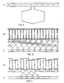
Figuren Figur 3 eine Draufsicht auf den Schaltring gemäß Fig. 1, 2,Figur 4 bis 8 in einem Querschnitt jeweils verschiedene Formen von Schaltring-Haken,Figur 9 das Wicklungs- und Anschlußschema einer in den achtzehn Nuten eines Läuferblechpaketes untergebrachten zweipoligen Universaimotor-Läuferwicklung,Figur 10 das Wicklungs- und Anschlußschema einer in den gleichen achtzehn Nuten des Läuferblechpaketes untergebrachten achpoligen Induktionsmotor-Läuferwicklung mit an neun Schaltringhaken angeschlossenen neun Spulenpaaren mit je zwei zu einem Kurzschlußkreis in Reihe geschalteten Einzelspulen,Figur 11 das Wicklungs- und Anschlußschema einer in achtzehn Nuten des Läuferblechpaketes untergebrachten sechspoligen Induktionsmotor-Läuferwicklung mit an vier Schaltringhaken angeschlossenen drei Spulenpaaren mit je drei zu einem Kurzschlußkreis in Reihe geschalteten Einzelspulen.
- FIGS. 1, 2 each show, in a longitudinal section, two different versions of a switching ring which is encapsulated in a separable cassette in front of a winding head of the runners
- FIG. 3 shows a top view of the switching ring according to FIGS. 1, 2,
- FIGS. 4 to 8 each have different shapes of switching ring hooks in a cross section,
- 9 shows the winding and connection diagram of a two-pole universal motor rotor winding accommodated in the eighteen slots of a rotor laminated core, FIG.
- FIG. 10 shows the winding and connection diagram of an axis-pole induction motor rotor winding accommodated in the same eighteen slots of the rotor laminated core, with nine coil pairs connected to nine switch ring hooks, each with two individual coils connected in series to form a short circuit,
- 11 shows the winding and connection diagram of a six-pole induction motor rotor winding accommodated in eighteen slots in the rotor laminated core with three coil pairs connected to four switch ring hooks, each with three individual coils connected in series to form a short circuit.
Die Figuren 1 und 2 zeigen jeweils in einem Längsschnitt zwei verschiedene Ausführungsformen des an der linken Stirnseite des Läufers in einer teilbaren Kassette 8 gekapselt gehaltenen Schaltrings S. In den Nuten des auf der Welle 7 angeordneten Läuferblechpaketes 9 ist radial innen zunächst die zweipolige Universalmotor-Wicklung 10 gemäß Fig. 1 und radial außen die in Fig. 2 hinsichtlich ihres Anschluß- und Wicklungsschemas dargestellte achtpolige Induktionsmotor-Wicklung angeordnet, deren über das Läuferblechpaket 9 axial hinausragender Wickelkopf das Bezugszeichen 5 trägt. Die Wicklungen sind gegenüber der Stirnseite des Läuberblechpaketes 9 und gegenüber der Welle 7 durch eine Isolierendscheibe 12 isoliert. Der in Fig. 3 in einer Draufsicht gezeigte Schaltring S besteht aus Elektrolytkupfer und weist an seinem Umfang verteilt neun Schaltringhaken S1 bis S9 auf. Diese Schaltringhaken können entsprechend den verschiedenen Ausführungsformen nach Fig.4 4 bis Fig. entweder radial (Fig. bis Fig. 6) oder axial (Fig. 7, 8) an den Schaltring S angeformt sein. Die Wahl der jeweiligen unterschiedlichen Schaltringhakenausführungen kann durch verschiedene Parameter, wie z. B. die Drahtdicke, die betriebliche mechanische Beanspruchung der Wicklung, die Drahtzugrichtung beim Bewickeln, die notwendige Kontaktfläche zwischen Schaltringhaken und Draht usw. bestimmt sein.FIGS. 1 and 2 each show in a longitudinal section two different embodiments of the switching ring S which is encapsulated in a
Zur isolierten und mechanisch sicheren Halterung ist der Schaltring S z. B. auf den zuvor auf die Welle 7 aufgeschobenen ersten Kassettenteil 81 der teilbaren Kassette 8 aufgesteckt und im Preßsitz gehalten. Anstelle dieser Preßsitzhalterung zwischen innerem Kassettenteil 81 und Schaltring S könnte in fertigungstechnisch günstiger Weise auch vorgesehen werden, den Schaltring als vorzugsweise offenen Ring in den inneren Kassettenteil 81 eingebettet zu halten. Der innere Kassetenteil 81 besteht vorzugsweise aus einem mit Rücksicht auf den Heißverstemmvorgang temperaturfesten Material. An sich könnte der innere Kassettenteil 81 auch mit der Isolierendsheibe 12 einstückig integriert sein, jedoch würde in einem solchen Fall auch die Isolierendscheibe 12 eine erhöhte Temperaturfestigkeit und damit einen höheren Materialaufwand erfordern.For isolated and mechanically secure mounting, the switching ring S z. B. on the previously pushed onto the
In Fig. 1, 2 ist in gestrichelter Form jeweils die Stellung des Schaltringhakens S6 nach dem Heißverstemmen gezeigt, bei dem durch Hitze der Isolierüberzug des Wicklungsdrahtes 13 entfernt und der Wicklungsdraht selbst mechanisch im Schaltringhaken eindeutig festgelegt wird. In vorteilhafter Weise ist vorgesehen, daß die Ver- ' bindungen der Wicklungsanfänge und Wicklungsenden mit den Schaltringhaken insgesamt und somit insbesondere die Außenoberfläche der Schaltringhaken frei von einem Isolierüberzug bleiben ; dies bedeutet insbesondere, daß bei einer abschließenden Gießharztränkung der Wickelköpfe keine Gießharzmasse zu den Schaltringhaken gelangt. Auf diese Art und Weise kann z. B. ein Wicklungs-Prüfgerät von außen an den Schaltring und somit an die Wicklung angeschlossen werden.In Fig. 1, 2, the position of the switching ring hook S6 after hot caulking is shown in broken lines, in which the insulating coating of the winding
In vorteilhafter Weise ist weiterhin vorgesehen, daß der Schaltring S mit seinen Schaltringhaken S1 bis S9-nach einem solchen Prüflauf dadurch isolierend und geschützt einkapselbar ist, daß abschließend der zweite Kassettenteil 82 in Form einer zum Wickelkopf der Läuferwicklung offenen, den Schaltring in seiner Endposition nach außen schützenden Abdeckglocke ausgebildet ist. Zweckmäßigerweise kann diese Abdeckgloche gleichzeitig als Nabendom für ein gesondert oder einstückig mit dem zweiten Kassettenteil verbundenes Lüfterrad 11 vorgesehend werden. Die Glockenwandung des zweiten Kassettenteils 82 weist außerdem ein axial auf den Wicklungsdraht 13 gerichtetes Andruckteil auf, das den ansonsten freien Wicklungsdraht 13 zwischen dem Wickelkopf 5 und dem Schaltring- haken S6 fixiert ; dazu ist als Gegenstück zum Andruckteil des zweiten Kassettenteils 82 eine entsprechende Anlegeschulter 811 am ersten Kassettenteil 81 angeformt. Bei dem Ausführungsbeispiel gemäß Fig. 1 ist das Andruckteil des zweiten Kassettenteils 82 als fertigungstechnisch besonders einfach herstellbare axial gerichtete Andrucknase 821, nach dem Ausführungsbeispiel gemäß Fig.2 als zusätzlich schräg nach außen in Richtung des Wicklungsdrahtes 13 hochgezogene, den Wicklungsdraht 13 über einen größeren Bereich abstützender sowie abdeckender und in vorteilhafter Weise mit Lüftungsöffnungen 823 versehener Andruckteller 822 ausgebildet.It is also advantageously provided that the switching ring S with its switching ring hooks S1 to S9 can be encapsulated in an insulated and protected manner after such a test run in that the
Die Figuren 10 und 11 zeigen zwei vorteilhafte Wicklungen für den eingangs genannten Motor, deren Fertigung mit Hilfe des Schaltringes wesentliche erleichtert, im Fall der Fig. 10 überhaupt erst für einen wirtschaftlichen Einsatz als Massenprodukt ermöglicht wird. Voraussetzung für die vorteilhafte Kombination der in Fig. 10, 11 dargestellten Wicklungsart einerseits und ihrer einfachen Verschaltung durch die Schaltring-Verbindungsvorrichtung andererseits ist die Erkenntnis, daß die bei bekannten Lösungen je für sich gebildeten und erst nach der gesamten Wicklung des Läufers einzeln verschalteten Kurzschlußkreis-Verbindungspunkte eines Wicklungsanfangs und eines Wicklungsendes einer jeden Spulengruppe untereinander verbunden werden können, ohne daß die prinzipielle Funktion des Motors gestört wird. Während bei der Wicklung gemäß Fig. 11 die Nutzahl N2 im Läufer der an sich üblichen Formel N2 = 2p - m2 . q2 entspricht, ist bei der Wicklung nach Fig. 10 die gesamte Nutzahl des Läufers unterschliedlich von der aufgrund von Polzahl, Phasenzahl und Nutzahl pro Pol und Strang für eine Ganzlochwicklung nach der Formel N2 = 2p - M2 . q2 bestimmbaren Nutzahl.FIGS. 10 and 11 show two advantageous windings for the motor mentioned at the outset, the manufacture of which is made considerably easier with the aid of the switching ring, in the case of FIG. 10 this is only possible for economical use as a mass product. A prerequisite for the advantageous combination of the type of winding shown in FIGS. 10, 11 on the one hand and their simple connection by the switching ring connecting device on the other hand is the knowledge that the short-circuit circuits which are formed in known solutions and are individually connected only after the complete winding of the rotor Connection points of a winding start and a winding end of each coil group can be connected to one another without the basic function of the motor being disturbed. 11, the usable number N2 in the rotor of the usual formula N 2 = 2p-m 2 . q is equal to 2, wherein the coil of Figure 10, the total number of slots of the rotor unterschliedlich the basis of pole number, phase number and number of slots per pole and phase for a full-slot winding according to the formula N 2 = 2p -. M 2. q 2 determinable number of uses.
Durch die freie Wahl der Nutzahlverhältnisse ist eine günstige Voraussetzung für die Auslegung eines Doppelfunktionsmotors mit geringen magnetischen Geräuschen geschaffen. Bisher war dies nur in Verbindung mit einer sogenannten vollintegrierten Wicklung gemäß der DE-B-27 44 472 mit jeweils beiden an einen gemeinsamen Kommutator angeschlossenen Wicklungen des Induktionsmotors und des Universalmotors möglich. Die Kombination zwischen der Wicklung gemäß Fig. 10, die an sich eine bisher nicht übliche Vielzahl von in bestimmter Weise zu verbindenden Wicklungsanfängen und Wicklungsenden beinhaltet, mit der erfindungsgemäßen Verbindungsvorrichtung ermöglicht die gemeinsame Ausnutzung der Vorteile der Motoren gemäß der eingangs genannten DE-B-25 30 294 und der DE-B-2444472. Vgl. zu den beschriebenen Wicklungen auch die prioritätsgleiche europäische-Anmeldung 82100812.5 (EP-A. 58352)The free choice of the usable ratios creates a favorable prerequisite for the design of a double-function motor with low magnetic noises. So far, this was only possible in connection with a so-called fully integrated winding according to DE-B-27 44 472, each with two windings of the induction motor and the universal motor connected to a common commutator. The combination between the winding according to FIG. 10, which in itself contains a previously not usual large number of winding starts and winding ends to be connected in a certain way, with the connecting device according to the invention enables the advantages of the motors according to the aforementioned DE-B-25 to be shared 30 294 and DE-B-2444472. See also the European application 82100812.5 (EP-A. 58352) of the same priority for the windings described.
Der Läufer gemäß Fig. 10 weist also abweichend von der aufgrund der Formel N2 = 2p - m2 . q2 sich ergebenden Nutzahl, achtzehn Nuten auf. Die Spulenweite w, der Spulen entspricht, so genau wie aufgrund dieser Nutzahl möglich, der einfachen Polteilung einer achtpoligen Induktionsmotor-Wicklung. Im vorliegenden Fall würde der genaue Wert der Polteilung τp = 45° geometrisch betragen ; aufgrund der gewählten Nutzahl ergibt sich ein praktischer Wert der Spulenweite von w, = 40° geometrisch. Der räumliche Winkelabstand zwischen zwei aufeinanderfolgenden Spulen einer Spulengruppe beträgt, wie aus Fig. 10 ohne weiteres ersichtlich, 180° geometrisch.10 thus deviates from that due to the formula N 2 = 2p - m 2 . q 2 resulting number of uses, eighteen grooves. The coil width w, which corresponds to the coils of an eight-pole induction motor winding, is as precise as possible on the basis of this number of uses. In the present case, the exact value of the pole pitch would be τ p = 45 ° geometrically; based on the selected number of uses, there is a practical value of the coil width of w = 40 ° geometrically. The spatial angular distance between two successive coils of a coil group is, as is readily apparent from FIG. 10, 180 ° geometrically.
Fig. zeigt zunächst die in den auch für die Induktionsmotor-Wicklung vorgesehenen Nuten N1 bis N18 des Läuferpaketes angeordnete zweipolige Universalmotor-Wicklung, wobei von dieser Wicklung nur eine einzige, an die Lamellen C6, C7 des Kollektors C angeschlossene, Schleifenwicklung dargestellt ist. Durch Anordnung des Schaltringes S an der Unterseite der in Fig. 10 bzw. 11 dargestellten Induktionsmotor-Wicklung einerseits und des Kollektors C an der Oberseite der in Fig. dargestellten Universalmotor-Wicklung soll angedeutet werden, daß insbesondere in für die maschinelle Fertigung der beiden Wicklungen vorteilhafter Weise Kollektor C und Schaltring S an gegenüberliegenden Stirnseiten des Läuferblechpaketes 9 anzuordnen sind.Fig. First shows the two-pole universal motor winding arranged in the slots N1 to N18 of the rotor assembly, which are also provided for the induction motor winding, only a single loop winding of this winding being connected to the lamellae C6, C7 of the collector C being shown. By arranging the switching ring S on the underside of the induction motor winding shown in FIGS. 10 and 11 on the one hand and the collector C on the top of the universal motor winding shown in FIG. 1, it is to be indicated that in particular for the mechanical production of the two windings Collector C and switching ring S are advantageously to be arranged on opposite end faces of the rotor laminated
Die in Fig. 10 dargestellte achtpolige Induktionsmotor-Wicklung kann unter Zuhilfenahme des für diese Wicklung vorteilhaften elektrisch leitenden und mit neuen Haken S1 bis S9 versehenen Schaltringes S wie folgt maschinell, z. B. mit Hilfe eines Flyers, auf einfache und betriebssichere Weise erfolgen : Der Anfang des ununterbrochenen Wicklungsdrahtes wird z. B. am Schaltringhaken S3 kontaktiert und zur Nut N3 gezogen, die Spule N3, N1 wird gewickelt, der Wicklungsdraht wird ohne Kontaktierung des Schaltrings S im Sinne einer Reihenschaltung zur nächsten Spule der die Spule N1, N3 enthaltenden Spulengruppen, nämlich zur Nut N12 gezogen, die Spule N12, N10 wird gewickelt, der Spulendraht wird zum nächstfolgenden Schaltringhaken S4 gezogen, um diesen eingelegt und zur Nut N5 gezogen, dann wird mit dem Wickeln der ersten Spule N5, N3 der nächstfolgenden Spulengruppen N5, N3 ; N14, N12 begonnen. Dieses Wicklungsverfahren wird fortgeführt, bis das Ende des Wicklungsdrahtes am Schaltringhaken S3 wieder angelangt und die gesamte Wicklung mit neun Spulenpaaren ohne Unterbrechung des Wicklungsdrahtes verschaltet ist. Durch Heißverstemmen kann dann die elektrische Kontaktierung und endgültige mechanische Festlegung zwischen den Schaltringhaken und dem einliegenden Wicklungsdraht erfolgen.The eight-pole induction motor winding shown in FIG. 10 can be machined with the aid of the electrically conductive switching ring S advantageous for this winding and provided with new hooks S1 to S9, as follows, for example. B. with the help of a flyer, in a simple and reliable manner: The beginning of the uninterrupted winding wire is z. B. contacted on the switching ring hook S3 and pulled to the slot N3, the coil N3, N1 is wound, the winding wire is pulled without contacting the switching ring S in the sense of a series connection to the next coil of the coil groups containing the coil N1, N3, namely to the slot N12, the coil N12, N10 is wound, the coil wire is drawn to the next switching ring hook S4, inserted around this and pulled to the groove N5, then with the winding of the first coil N5, N3 the next coil groups N5, N3; N14, N12 started. This winding process is continued until the end of the winding wire reaches the switching ring hook S3 again and the entire winding is connected to nine pairs of coils without interrupting the winding wire. By hot caulking, the electrical contacting and final mechanical fixing between the Switch ring hook and the inserted winding wire.
Fig. 11 zeigt eine Wicklung mit N2 = 2p - M2 - q2 Nuten im Läufer. Jede Spulengruppe besteht aus drei Spulenpaaren mit je drei in Reihe geschalteten Spulen. Ein erstes Spulenpaar umfaßt z. B. die Spulen N1, N4 ; N7, N10 ; N13, N16. Die Reihenschaltungen sind über die Verbindungen der Schaltringhaken S1 bis S4 jeweils zu Kurzschlußkreisen zusammengehaltet, wobei auch im Fall gemäß Fig. 11 die gesamte Wicklung mit einem ununterbrochenen Wicklungsdraht fortschreitend wickelbar ist. Für den Schaltring S ist in Fig. 10 und Fig. 11 die gleiche Schaltring-Bauart als Einheitsbauteil verwendet.Fig. 11 shows a winding with N 2 = 2p - M2 - q 2 slots in the rotor. Each coil group consists of three pairs of coils, each with three coils connected in series. A first pair of coils comprises e.g. B. the coils N1, N4; N7, N10; N13, N16. The series connections are each held together to form short-circuit circuits via the connections of the switching ring hooks S1 to S4, the entire winding also being able to be progressively wound with an uninterrupted winding wire in the case according to FIG. 11. For the switching ring S, the same switching ring type is used as a unit component in FIGS. 10 and 11.
Claims (12)
Priority Applications (1)
| Application Number | Priority Date | Filing Date | Title |
|---|---|---|---|
| AT82100810T ATE13733T1 (en) | 1981-02-13 | 1982-02-04 | CONNECTING DEVICE FOR WINDING STARTS AND END WINDINGS OF THE INDUCTION MOTOR ROTOR WINDING OF AN ELECTRIC MOTOR. |
Applications Claiming Priority (2)
| Application Number | Priority Date | Filing Date | Title |
|---|---|---|---|
| DE3105318 | 1981-02-13 | ||
| DE3105318A DE3105318C2 (en) | 1981-02-13 | 1981-02-13 | Arrangement for short-circuiting the beginnings and ends of the coil groups of an induction motor rotor winding of an electric two-motor drive |
Publications (2)
| Publication Number | Publication Date |
|---|---|
| EP0058351A1 EP0058351A1 (en) | 1982-08-25 |
| EP0058351B1 true EP0058351B1 (en) | 1985-06-05 |
Family
ID=6124824
Family Applications (1)
| Application Number | Title | Priority Date | Filing Date |
|---|---|---|---|
| EP82100810A Expired EP0058351B1 (en) | 1981-02-13 | 1982-02-04 | Connecting device for the beginnings and ends of the coils of an induction motor rotor winding |
Country Status (8)
| Country | Link |
|---|---|
| EP (1) | EP0058351B1 (en) |
| AT (1) | ATE13733T1 (en) |
| CS (1) | CS235007B2 (en) |
| DD (1) | DD209328A5 (en) |
| DE (2) | DE3105318C2 (en) |
| DK (1) | DK58082A (en) |
| HU (1) | HU183821B (en) |
| PL (1) | PL136486B1 (en) |
Families Citing this family (5)
| Publication number | Priority date | Publication date | Assignee | Title |
|---|---|---|---|---|
| DE19832680C2 (en) * | 1998-07-21 | 2001-03-29 | Sachsenwerk Gmbh | Variable switching connection for the winding starts and ends of a rotor winding of a rotating electrical machine |
| US6147423A (en) * | 1999-09-30 | 2000-11-14 | Reliance Electric Technologies, Llc | Electric motor having improved rotor assembly, and method by which the rotor assembly is made |
| AU782017B2 (en) | 1999-10-18 | 2005-06-30 | Lg Electronics Inc. | A driving unit for a drum type washing machine |
| EP1815581A1 (en) * | 2004-11-26 | 2007-08-08 | Matsushita Electric Industrial Co., Ltd. | Commutator motor and method of manufacturing the same |
| CN108599496B (en) * | 2018-05-08 | 2019-07-23 | 刘建平 | Double-stator permanent magnet asynchronous motor and its speed-regulating control circuit |
Family Cites Families (8)
| Publication number | Priority date | Publication date | Assignee | Title |
|---|---|---|---|---|
| DE276610C (en) * | ||||
| US1803493A (en) * | 1927-11-12 | 1931-05-05 | Volet Rene Alfred Laurent | Rotor |
| FR740581A (en) * | 1931-08-03 | 1933-01-27 | Brown | Double squirrel cage armature motor |
| US3144572A (en) * | 1962-03-26 | 1964-08-11 | Smader Charles Louis | Terminal construction for electric motors |
| FR2247842A1 (en) * | 1973-10-10 | 1975-05-09 | Ferodo Sa | Rotor design for low power electric motor - ends of winding slot walls have winding guide discs with inclined fingers |
| DE2530294C3 (en) * | 1975-07-07 | 1982-10-28 | Siemens AG, 1000 Berlin und 8000 München | Electric washing machine drive |
| DE2643904C3 (en) * | 1976-09-29 | 1979-03-15 | Siemens Ag, 1000 Berlin Und 8000 Muenchen | Induction motor with a wound rotor winding inserted in rotor slots |
| DE2744419C2 (en) * | 1977-10-03 | 1985-02-21 | Siemens AG, 1000 Berlin und 8000 München | Hook commutator |
-
1981
- 1981-02-13 DE DE3105318A patent/DE3105318C2/en not_active Expired
-
1982
- 1982-02-04 CS CS82788A patent/CS235007B2/en unknown
- 1982-02-04 DE DE8282100810T patent/DE3263972D1/en not_active Expired
- 1982-02-04 EP EP82100810A patent/EP0058351B1/en not_active Expired
- 1982-02-04 AT AT82100810T patent/ATE13733T1/en not_active IP Right Cessation
- 1982-02-05 DD DD82237226A patent/DD209328A5/en not_active IP Right Cessation
- 1982-02-11 DK DK58082A patent/DK58082A/en not_active Application Discontinuation
- 1982-02-12 HU HU82444A patent/HU183821B/en not_active IP Right Cessation
- 1982-02-12 PL PL1982235047A patent/PL136486B1/en unknown
Also Published As
| Publication number | Publication date |
|---|---|
| ATE13733T1 (en) | 1985-06-15 |
| EP0058351A1 (en) | 1982-08-25 |
| HU183821B (en) | 1984-06-28 |
| PL136486B1 (en) | 1986-02-28 |
| PL235047A1 (en) | 1982-09-13 |
| DK58082A (en) | 1982-08-14 |
| DE3105318C2 (en) | 1983-10-06 |
| DD209328A5 (en) | 1984-04-25 |
| CS235007B2 (en) | 1985-04-16 |
| DE3263972D1 (en) | 1985-07-11 |
| DE3105318A1 (en) | 1982-08-19 |
Similar Documents
| Publication | Publication Date | Title |
|---|---|---|
| DE60119051T2 (en) | electric motor | |
| DE2211184C3 (en) | Disc anchor | |
| DE10056555A1 (en) | Stator for dynamo-electrical machines | |
| DE19917579A1 (en) | Dynamo electric machine for generation of electric power | |
| DE2744419A1 (en) | ELECTRIC MOTOR WITH HOOK COMMUTATOR | |
| WO2009000586A2 (en) | Winding body for an electric motor and method for producing a winding body for an electric motor | |
| EP0058351B1 (en) | Connecting device for the beginnings and ends of the coils of an induction motor rotor winding | |
| DE102014217289A1 (en) | Winding arrangement and method for producing a winding arrangement | |
| EP2994980B1 (en) | Continuous stator winding wound on a coil carrier | |
| DE19757279C1 (en) | Commutator motor, in particular for driving a motor vehicle servo drive, and method for its production | |
| DE2117048C3 (en) | Process for the production of a disk-shaped wave winding from insulated wire for an electric axial air gap machine | |
| WO2019057597A1 (en) | Electric machine | |
| DE3105300C2 (en) | Electric two-motor drive, in particular for driving a washing machine | |
| DE102018113422A1 (en) | Engine with a single-prism air gap winding | |
| EP0809345A1 (en) | Method of manufacturing a rotor unit for an angular-position indicator with rotary transformer and coil bobbin to be used in this method | |
| DE102020114065A1 (en) | Stator for an electric motor | |
| DE8104018U1 (en) | CONNECTING DEVICE WITH DETERMINED WINDING BEGINNINGS AND WINDING END OF INDUCTION MOTOR-RUNNER WINDING OF AN ELECTRIC TWO-MOTOR DRIVE | |
| DE102009001543A1 (en) | Electric machine and method for manufacturing an electric machine | |
| DE2134490C3 (en) | Shaded pole motor | |
| DE3012506A1 (en) | COMMUTATOR MOTOR | |
| DE202010002424U1 (en) | Device for converting electrical energy into mechanical energy and / or vice versa, as well as wound bodies for such a device | |
| DE2609776C2 (en) | Compensating conductor arrangement for armature windings | |
| DE8104002U1 (en) | ELECTRIC TWO-MOTOR DRIVE, ESPECIALLY TO DRIVE A WASHING MACHINE | |
| DE1613787A1 (en) | Single-phase asynchronous motor | |
| DE2746995A1 (en) | Electric motor with hooked commutator - has hook at segment end, with recess below surface for at least one winding wire |
Legal Events
| Date | Code | Title | Description |
|---|---|---|---|
| PUAI | Public reference made under article 153(3) epc to a published international application that has entered the european phase |
Free format text: ORIGINAL CODE: 0009012 |
|
| AK | Designated contracting states |
Designated state(s): AT BE CH DE FR GB IT NL SE |
|
| 17P | Request for examination filed |
Effective date: 19820916 |
|
| ITF | It: translation for a ep patent filed |
Owner name: STUDIO JAUMANN |
|
| GRAA | (expected) grant |
Free format text: ORIGINAL CODE: 0009210 |
|
| AK | Designated contracting states |
Designated state(s): AT BE CH DE FR GB IT LI NL SE |
|
| REF | Corresponds to: |
Ref document number: 13733 Country of ref document: AT Date of ref document: 19850615 Kind code of ref document: T |
|
| REF | Corresponds to: |
Ref document number: 3263972 Country of ref document: DE Date of ref document: 19850711 |
|
| ET | Fr: translation filed | ||
| PLBE | No opposition filed within time limit |
Free format text: ORIGINAL CODE: 0009261 |
|
| STAA | Information on the status of an ep patent application or granted ep patent |
Free format text: STATUS: NO OPPOSITION FILED WITHIN TIME LIMIT |
|
| 26N | No opposition filed | ||
| PGFP | Annual fee paid to national office [announced via postgrant information from national office to epo] |
Ref country code: CH Payment date: 19890524 Year of fee payment: 8 |
|
| PG25 | Lapsed in a contracting state [announced via postgrant information from national office to epo] |
Ref country code: LI Effective date: 19900228 Ref country code: CH Effective date: 19900228 |
|
| PGFP | Annual fee paid to national office [announced via postgrant information from national office to epo] |
Ref country code: NL Payment date: 19900228 Year of fee payment: 9 |
|
| PGFP | Annual fee paid to national office [announced via postgrant information from national office to epo] |
Ref country code: BE Payment date: 19900301 Year of fee payment: 9 |
|
| REG | Reference to a national code |
Ref country code: CH Ref legal event code: PL |
|
| PGFP | Annual fee paid to national office [announced via postgrant information from national office to epo] |
Ref country code: GB Payment date: 19910118 Year of fee payment: 10 |
|
| PGFP | Annual fee paid to national office [announced via postgrant information from national office to epo] |
Ref country code: SE Payment date: 19910222 Year of fee payment: 10 |
|
| ITTA | It: last paid annual fee | ||
| PG25 | Lapsed in a contracting state [announced via postgrant information from national office to epo] |
Ref country code: BE Effective date: 19910228 |
|
| PG25 | Lapsed in a contracting state [announced via postgrant information from national office to epo] |
Ref country code: NL Effective date: 19910901 |
|
| NLV4 | Nl: lapsed or anulled due to non-payment of the annual fee | ||
| PGFP | Annual fee paid to national office [announced via postgrant information from national office to epo] |
Ref country code: AT Payment date: 19920129 Year of fee payment: 11 |
|
| PG25 | Lapsed in a contracting state [announced via postgrant information from national office to epo] |
Ref country code: GB Effective date: 19920204 |
|
| PG25 | Lapsed in a contracting state [announced via postgrant information from national office to epo] |
Ref country code: SE Effective date: 19920205 |
|
| PGFP | Annual fee paid to national office [announced via postgrant information from national office to epo] |
Ref country code: FR Payment date: 19920220 Year of fee payment: 11 |
|
| GBPC | Gb: european patent ceased through non-payment of renewal fee | ||
| PG25 | Lapsed in a contracting state [announced via postgrant information from national office to epo] |
Ref country code: AT Effective date: 19930204 |
|
| PG25 | Lapsed in a contracting state [announced via postgrant information from national office to epo] |
Ref country code: FR Effective date: 19931029 |
|
| REG | Reference to a national code |
Ref country code: FR Ref legal event code: ST |
|
| PGFP | Annual fee paid to national office [announced via postgrant information from national office to epo] |
Ref country code: DE Payment date: 19940419 Year of fee payment: 13 |
|
| EUG | Se: european patent has lapsed |
Ref document number: 82100810.9 Effective date: 19920904 |
|
| PG25 | Lapsed in a contracting state [announced via postgrant information from national office to epo] |
Ref country code: DE Effective date: 19951101 |