EP0057930A2 - Hydraulischer Antrieb mit mehreren Motoren - Google Patents
Hydraulischer Antrieb mit mehreren Motoren Download PDFInfo
- Publication number
- EP0057930A2 EP0057930A2 EP82100900A EP82100900A EP0057930A2 EP 0057930 A2 EP0057930 A2 EP 0057930A2 EP 82100900 A EP82100900 A EP 82100900A EP 82100900 A EP82100900 A EP 82100900A EP 0057930 A2 EP0057930 A2 EP 0057930A2
- Authority
- EP
- European Patent Office
- Prior art keywords
- hydraulic
- valve
- pressure
- pilot
- directional control
- Prior art date
- Legal status (The legal status is an assumption and is not a legal conclusion. Google has not performed a legal analysis and makes no representation as to the accuracy of the status listed.)
- Granted
Links
- 239000012530 fluid Substances 0.000 claims abstract description 60
- 238000006073 displacement reaction Methods 0.000 claims abstract description 44
- 238000004891 communication Methods 0.000 claims description 6
- 230000000903 blocking effect Effects 0.000 claims 1
- 230000007935 neutral effect Effects 0.000 description 21
- 238000000034 method Methods 0.000 description 13
- 230000008569 process Effects 0.000 description 13
- 238000010276 construction Methods 0.000 description 4
- 238000010586 diagram Methods 0.000 description 4
- 238000012986 modification Methods 0.000 description 4
- 230000004048 modification Effects 0.000 description 4
- 230000036316 preload Effects 0.000 description 4
- 230000007423 decrease Effects 0.000 description 3
- 239000000314 lubricant Substances 0.000 description 2
- 230000002159 abnormal effect Effects 0.000 description 1
- 230000000694 effects Effects 0.000 description 1
- 230000009467 reduction Effects 0.000 description 1
Images


Classifications
-
- F—MECHANICAL ENGINEERING; LIGHTING; HEATING; WEAPONS; BLASTING
- F16—ENGINEERING ELEMENTS AND UNITS; GENERAL MEASURES FOR PRODUCING AND MAINTAINING EFFECTIVE FUNCTIONING OF MACHINES OR INSTALLATIONS; THERMAL INSULATION IN GENERAL
- F16H—GEARING
- F16H61/00—Control functions within control units of change-speed- or reversing-gearings for conveying rotary motion ; Control of exclusively fluid gearing, friction gearing, gearings with endless flexible members or other particular types of gearing
- F16H61/38—Control of exclusively fluid gearing
- F16H61/40—Control of exclusively fluid gearing hydrostatic
- F16H61/44—Control of exclusively fluid gearing hydrostatic with more than one pump or motor in operation
- F16H61/444—Control of exclusively fluid gearing hydrostatic with more than one pump or motor in operation by changing the number of pump or motor units in operation
-
- E—FIXED CONSTRUCTIONS
- E02—HYDRAULIC ENGINEERING; FOUNDATIONS; SOIL SHIFTING
- E02F—DREDGING; SOIL-SHIFTING
- E02F9/00—Component parts of dredgers or soil-shifting machines, not restricted to one of the kinds covered by groups E02F3/00 - E02F7/00
- E02F9/08—Superstructures; Supports for superstructures
- E02F9/10—Supports for movable superstructures mounted on travelling or walking gears or on other superstructures
- E02F9/12—Slewing or traversing gears
- E02F9/121—Turntables, i.e. structure rotatable about 360°
- E02F9/123—Drives or control devices specially adapted therefor
-
- F—MECHANICAL ENGINEERING; LIGHTING; HEATING; WEAPONS; BLASTING
- F16—ENGINEERING ELEMENTS AND UNITS; GENERAL MEASURES FOR PRODUCING AND MAINTAINING EFFECTIVE FUNCTIONING OF MACHINES OR INSTALLATIONS; THERMAL INSULATION IN GENERAL
- F16H—GEARING
- F16H61/00—Control functions within control units of change-speed- or reversing-gearings for conveying rotary motion ; Control of exclusively fluid gearing, friction gearing, gearings with endless flexible members or other particular types of gearing
- F16H61/38—Control of exclusively fluid gearing
- F16H61/40—Control of exclusively fluid gearing hydrostatic
- F16H61/4078—Fluid exchange between hydrostatic circuits and external sources or consumers
-
- F—MECHANICAL ENGINEERING; LIGHTING; HEATING; WEAPONS; BLASTING
- F16—ENGINEERING ELEMENTS AND UNITS; GENERAL MEASURES FOR PRODUCING AND MAINTAINING EFFECTIVE FUNCTIONING OF MACHINES OR INSTALLATIONS; THERMAL INSULATION IN GENERAL
- F16H—GEARING
- F16H61/00—Control functions within control units of change-speed- or reversing-gearings for conveying rotary motion ; Control of exclusively fluid gearing, friction gearing, gearings with endless flexible members or other particular types of gearing
- F16H61/38—Control of exclusively fluid gearing
- F16H61/40—Control of exclusively fluid gearing hydrostatic
- F16H61/42—Control of exclusively fluid gearing hydrostatic involving adjustment of a pump or motor with adjustable output or capacity
- F16H61/433—Pump capacity control by fluid pressure control means
-
- F—MECHANICAL ENGINEERING; LIGHTING; HEATING; WEAPONS; BLASTING
- F16—ENGINEERING ELEMENTS AND UNITS; GENERAL MEASURES FOR PRODUCING AND MAINTAINING EFFECTIVE FUNCTIONING OF MACHINES OR INSTALLATIONS; THERMAL INSULATION IN GENERAL
- F16H—GEARING
- F16H59/00—Control inputs to control units of change-speed- or reversing-gearings for conveying rotary motion
- F16H59/68—Inputs being a function of gearing status
- F16H2059/6838—Sensing gearing status of hydrostatic transmissions
- F16H2059/6861—Sensing gearing status of hydrostatic transmissions the pressures, e.g. high, low or differential pressures
Definitions
- This invention relates to a hydraulic drive system comprising at least one hydraulic actuator, a plurality of hydraulic pumps connected in parallel with one another and each connected to said actuator to form a closed circuit therewith, and a plurality of prime movers each for driving the plurality of hydraulic pumps, which is suitable for driving a hydraulic shovel of a large size, for example.
- a hydraulic drive system which comprises a single variable displacement hydraulic pump connected to one or a plurality of hydraulic actuators to form a closed circuit therewith.
- operation of the actuators is controlled by controlling the direction in which the pump delivers pressure fluid and the flow rate of the delivered pressure fluid without using a directional control valve mounted between the hydraulic pump and the actuators.
- a hydraulic drive system has come into use which, to cope with an inrease in the size of hydraulic shovels and hence an increase in the size of the hydraulic actuators, comprises two variable displacement hydraulic pumps connected in parallel with each other and each connected to hydraulic actuators to form a.closed circuit therewith.
- the two hydraulic pumps are driven by separate prime movers, and operation' of the actuators is controlled by controlling the direction in which the two hydraulic pumps deliver the pressure fluid and the flow rate of the delivered pressure fluid by the pumps with a common operation signal.
- the pressure fluid delivered by the two hydraulic pumps can be used in good condition for operating the actuator so long as the two prime movers normally operate.
- the pressure fluid delivered by the hydraulic pump connected to the normally operating prime mover is supplied to the other hydraulic pump and might cause same to rotate in the reverse direction, or the hydraulic pump might perform the function of a motor to thereby cause the prime mover connected to the hydraulic pump and other pumps connected to the prime mover, such as, lubricant pump, pilot pump and hydraulic pump for other hydraulic circuit, etc. to rotate in the reverse direction, to thereby cause damage thereto.
- An object of this invention is to provide a novel hydraulic drive system comprising a plurality of variable displacement hydraulic pumps connected in parallel with each other and connected to at least one hydraulic actuator, and a plurality of prime movers each driving the plurality of hydraulic pumps, wherein the prime mover not in normal operating condition can be prevented from being forcedly rotated by the variable displacement hydraulic pump connected thereto which might function as a hydraulic motor.
- Another object of the present invention is to provide a hydraulic drive system of the type described which is provided with means for fluidly cutting the hydraulic pump connected to the prime mover not in normal operating condition off the other hydraulic pump and the hydraulic actuator or actuators.
- Still another object of the invention is to provide a hydraulic drive system of the type described which is capable, when the hydraulic actuator is stopped or when the flow rate of the pressure fluid delivered by the hydraulic pumps is zero (0), of fluidly cutting the hydraulic actuator off the hydraulic pumps, to thereby positively keep the hydraulic actuator in the stopped condition.
- Fig. 1 shows the hydraulic drive system comprising one embodiment of the invention for driving a single load 11.
- the hydraulic drive system comprises two hydraulic actuators or motors 7a and 7b drivingly connected to the load 11 via a gearing 10, two variable displacement hydraulic pumps 3a and 3b, and prime movers la and lb for driving the hydraulic pumps 3a and 3b.
- hydraulic pumps 2a and 2b for another hydraulic drive system and pilot pumps 4a and 4b for producing control pressures' are also driven by the two prime movers la and lb.
- the one variable displacement hydraulic pump 3a is connected through main lines 5a and 6a, a directional control valve 21a and main lines 8 and 9 to the two hydraulic motors 7a and 7b to form closed circuits therewith respectively, and the other variable displacement hydraulic pump 3b is also connected through main lines 5b and 6b, a directional control valve 21b and the main lines 8 and 9 to the two hydraulic pumps 7a and 7b to form closed circuits therewith respectively.
- the one hydraulic motor 7a has connected thereto the two hydraulic pumps 3a and 3b which are connected in parallel with each other at parallel connection points 8a and 9a
- the other hydraulic motor 7b has connected thereto the two hydraulic pumps 3a and 3b which are connected in parallel with each other at parallel connection points 8b and 9b.
- Overload relief valves 20 are mounted between the main lines 8 and 9 for setting the highest pressure for the main lines.
- the directional control valves 21a and 21b are for selectively shutting the associated hydraulic pumps 3a and 3b off the hydraulic motors and other hydraulic pumps and their details will be described later.
- variable displacement hydraulic pumps may be in the form of plunger pumps provided with means 12a and 12b respectively for varying the displacement volume, such as a swash plate or eccentric shaft.
- the displacement volume varying means 12a and 12b have connected thereto known regulators comprising control cylinders 13a and 13b, servo valves 14a and 14b and cut-off valves 15a and 15b respectively.
- the one control cylinder 13a is connected through the servo valve 14a and cut-off valve 15a to a control pressure line 40a connected to the pilot pump 4a, to receive a supply of pressure fluid from the pump 4a.
- the other control cylinder 13b is connected through the servo valve 14b and cut-off valve 15b to a control pressure line 40b connected to the pilot pump 4b, to receive a supply of pressure fluid from the pump 4b.
- the lines 40a and 40b are connected to a common control pressure line 41 through check valves 17a and 17b respectively.
- the line 41 has connected thereto a relief valve 19 to keep the pressures in the lines 40a, 40b and 41 from exceeding a predetermined adjusted value.
- the servo valves 14a and 14b are pilot-operated, three-position valves and movable between opposite extreme positions A and C and a normal neutral position B.
- the servo valves 14a and 14b have movable sleeves connected to pistons of the control cylinders 13a and 13b respectively.
- a pair of mannally-operated pilot valves 18A and 18B supply pilot pressures to the servo valves 14a and 14b respectively.
- the pilot valves 18A and 18B are variable reduce valves inputting an adjusted pressure from the line 41 and supply to output lines 43A and 43B a pressure proportional to the manipulated variable of manually-operated levers 42A and 42B.
- the one output line 43A is connected to the two servo valves 14a and 14b in a manner to apply pressure thereto to shift same to position A, and the other output line 43B is connected thereto to apply pressure thereto to shift same to position C.
- the two servo valves 14a and 14b are simultaneously actuated by one manually-operated valve 18A or 18B.
- the cut-off valve 15a is a pilot-operated, two-position valve and movable between a normal position A in which it allows lines 44a and 45a to communicate with each other and a position B in which it releases pressure fluid from the line 45a.
- the cut-off valve 15a receives as a pilot pressure a higher main line pressure through a shuttle valve 16a arranged between the main lines 5a and 6a and a line 46a.
- the other cut-off valve 15b is also a pilot-operated, two-position valve and movable between a normal position A in which it allows lines 44b and 45b to communicate with each other and a position B in which it releases pressure fluid from the line 45b.
- the cut-off valve 15b receives as a pilot pressure a higher main line pressure through a shuttle valve l6b arranged between the main lines 5b and 6b and a line 46b.
- the directional control valve 21a is a pilot-operated, two-position valve having two input ports connected to the main lines 5a and 6a on the hydraulic pump 3a side and two output ports connected to the main lines 8 and 9 on the hydraulic motor side.
- the valve 21a is movable between a normal position A to which it is biased by a spring and a position B to which it is switched by a pilot pressure. When the valve 21a is in position A, the two input ports are brought into communication with each other and the two output ports are individually blocked. When it is'in position B, the two input ports are in communication with the output ports respectively.
- the valve 21a receives a pilot pressure through a line 47a from the line 40a which receives a supply of pressure fluid from the pilot pump 4a.
- the directional control valve 21b which is of the same construction as the directional control valve 21a, receives a pilot pressure through a line 47b from the line 40b which receives a supply of pressure fluid from the pilot pump 4b.
- the directional control valves 21a and 21b each move to position B under the influence of a predetermined adjusted pressure which is produced by the pilot pumps 4a and 4b in the lines 40a, 40b and 41, when the prime movers la and lb normally operate.
- valves 21a and 21b are moved to the normal position A by the biasing force of the spring.
- the downward shift of the piston actuates the displacement volume varying means 12a, to cause the hydraulic pump 3a to begin to deliver pressure fluid to the main line 5a.
- the shift of the piston being fed back to the sleeve of the servo valve 14a; the piston comes to a halt after moving a distance corresponding to the distance covered by the movement of the valve spool of the servo valve 14a.
- the flow rate of the pressure fluid delivered by the hydraulic pump 3a has a value which is commensurate with the distance covered by the movement of the valve spool or the amount of displacement of the operation lever 42A of the pilot valve 18A.
- the upward shift of the servo valve 14b actuates the displacement volume varying means 12b of the hydraulic pump 3b, to cause the hydraulic pump 3b to begin to deliver to the main line 5b a supply of pressure fluid at a flow rate commensurate with the amount of displacement of the operation lever 42A.
- the pressure fluid from the hydraulic pumps 3a and 3b flows through the main lines 5a_and 5b into the common main line 8 and actuates the hydraulic motors 7a and 7b to drive the load 11.
- the pressure fluid flows into the main line 9 from which it is returned to the hydraulic pumps 3a and 3b via the main lines 6a and 6b respectively.
- the displacement volume of the variab displacement hydraulic pumps 3a and 3b is adjusted in reverse, to thereby reduce the pressure in the main lines on the higher pressure side.
- the flow rate of the pressure fluid delivered by the hydraulic pumps 3a and 3b slowly changes to the amount corresponding to that of manipulation of the pilot valve 18A while the pressure in the main lines on the higher pressure side is being: restricted to a level below the level set for switching the cut-off valves 15a and 15b.
- the hydraulic pumps 3a and 3b deliver pressure fluid to the main lines 6a and 6b respectively, to thereby rotate the hydraulic motors 7a and 7b in a direction opposite the direction in which they are rotated when the one pilot valve 18A is actuated.
- the hydraulic pumps 3a and 3b are simultaneously controlled by the pilot valves 18A and 18B, to thereby actuate the hydraulic motors 7a and 7b, in case where both prime movers la and lb are normally operating.
- the pilot valves 18A and 18B to thereby actuate the hydraulic motors 7a and 7b, in case where both prime movers la and lb are normally operating.
- one of the prime movers is shut down for some reason.
- the prime mover la may be shut down due to an increase in the load applied thereto by the increase in the pressure fluid delivered by the pump 3a.
- the pilot pump 4a connected to the prime mover la will stop rotating, and its delivery pressure or the pressure of the line 40a will drop.
- a drop in the pressure in the lines 40a allows the directional control valve 21a to move to position A, thereby shutting the hydraulic pump 3a off the hydraulic motors 7a and ' Jb and the other hydraulic pump 3b.
- the hydraulic motors 7a and 7b are operated only by the pressure fluid from the hydraulic pump 3b.
- the variable displacement hydraulic pump 3a is prevented from functioning as a hydraulic motor by using the pressure fluid from the pump 3b, so that the prime mover la is prevented from being rotated by the pump 3a functioning as a hydraulic motor.
- the directional control valve 21a shifts from position B to position A, a small volume of pressure fluid may be delivered by the hydraulic pressure pump 3a. This raises no problem because the pressure fluid delivered in this way is returned to the suction port of the pump 3a through the control valve 21a in position A.
- the control pressure applied to the control cylinder 13a or the pressure in the line 40a becomes zero (0), so that the piston of the control cylinder 13a returns to a neutral position and comes to a halt irrespective of the position of the servo valve 14a.
- the other prime mover lb continues its normal operation and the normal adjusted pressure is applied by the pilot pump 4b to the lines 40b and 41, so that the hydraulic pump 3b is normally controlled by the pilot valves 18A and 18B and the hydraulic motors 7a and 7b are driven by the pressure fluid sppplied by the hydraulic pump 3b.
- Fig. 2 shows another embodiment of the invention in which parts similar to those shown in Fig. 1 are designated by like reference characters.
- This embodiment also comprises the pilot-operated directional control valves 21a and 2lb mounted between the main lines 5a and 6a and main lines 8 and 9 and between the main lines 5b and 6b and the main lines 8 and 9 respectively.
- the valves 21a and 21b are of the same construction as those shown and described by referring to the embodiment shown in Fig. 1, but the channel through which a pilot pressure is supplied is distinct from the channel through which a pilot pressure is supplied by the counterparts shown in Fig. 1.
- the valve 21a receives a pilot pressure through a shuttle valve 22a mounted between two lines 48a and 49a connected to the control cylinder 13a for taking out a higher pressure, a line 50a, a pilot-operated change-over valve 23a and a line 51a.
- the change-over valve 23a is movable between a normal position A in which it releases pressure fluid from the line 5la and a position B in which it allows the lines 50a and 51a to communicate with each other, and the pilot pressure is supplied from the line 40a through a line 52a.
- the directional control valve 21b receives a pilot pressure through a shuttle valve 22b, a line 50b, a change-over valve 23b and a line 51b, the change-over valve 23b receiving a pressure from the line 40b through a line 52b.
- the change-over valves 23a and 23b return to normal position A when the number of revolutions of the prime movers la and lb drops to a predetermined level lower than the normal rpm thereof and the pressure in the lines 40a and 40b shows a correspondin g .drop.
- the control cylinder 13a has neutral position restoring springs 56 and 57 and movable spring seats 58 and 59 located in pressure chambers 54 and 55 respectively.
- the spring seats 58 and 59 are forced against shoulders 60 and 61 respectively of the cylinder body when the piston is in a neutral position.
- a predetermined preload is applied to the springs 56 and 57 when the piston is in the neutral position as shown.
- the preload applied to the springs 56 and 57 is set at a level such that a pressure high enough to shift the control valve 21a to position B is generated in the pressure chamber 54 or 55 before the piston begins to move from the neutral position.
- the control cylinder 21b is of the same construction as the control cylinder 21a.
- Other parts of the embodiment shown in Fig. 2 are similar to those of the embodiment shown in Fig. 1, so that their description will be omitted.
- the lines 48a and 49a and lines 48b and 49b connected to the pressure chambers of the cylinders 13a and 13b respectively have the pressure discharged therefrom, so that no pilot pressure is' supplied to the control valves 21a and 21b and the velves 21a and 21b are in normal position A. Because of this, the main lines 8 and 9 connected to the hydraulic. motors 7a and 7b are closed at their ends. Thus the hydraulic motors 7a and 7b are prevented from being rotated by an external force exerted on the load 11 when they are shut down, to ensure that the hydraulic motors 7a and 7b and the load 11 are kept stopped without being operated by an external force.
- the pilot valve 18A or 18B are actuated. Actuation of the pilot valves 18A and 18B controls the displacement volume varying means 12a and 12b of the hydraulic pumps 3a and 3b respectively in the same process as described by referring to the embodiment shown in Fig. 1, so that the delivery by the hydraulic pumps is varied by following up the amount of operation of the pilot valves 18A and 18B.
- the rpm of the hydraulic pirot pump 4a connected to the prime mover la also decreases and the pressure in the line 40a drops.
- a drop in the pressure in the line 40a enables the change-over valve 23a to return to normal position A, thereby releasing pressure fluid from the line 51a.
- Release of pressure fluid from the line 5la enables the control valve 21a to return to position A as shown, so that the hydraulic pump 3a is shut by the control valve 21a off the other hydraulic pump 3b and the hydraulic motors 7a and 7b.
- the other hydraulic pump is prevented from supplying pressure fluid to the hydraulic pump 3a connected to the prime mover la having its rpm reduced to an inordinately low level or shut down, so that the hydraulic pump 3a is kept from acting as a motor.
- the hydraulic pumps 3a and 3b deliver pressure fluid at a flow rate commensurate with the amount of operation of the pilot valve 18A or 18B, to thereby drive the hydraulic motors 7a and 7b respectively.
- the pilot valve being returned to a neutral position to shut down the hydraulic pumps 3a and 3b and the load 11
- the pistons of the hydraulic cylinders 13a and 13b are moved by the servo valves 14a and 14b toward a neutral position to also move the displacement volume varying means 12a and 12b of the hydraulic pumps 3a and 3b respectively to a neutral position, thereby reducing the flow rate of pressure fluid delivered by the pumps.
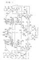
- FIGs. 4 and 5 show modifications to the directional control valve 21a of the embodiment shown in Fig. 2.
- a four-port, two-position valve 21a' provided with no internal bypass passage is used, and a bypass passage 70 mounting a shut-off valve 71 connects the main lines 5a and 6a together.
- valves 21a' and 71 are simultaneously switched by the pressure in a line 51a' corresponding to the line 51a shown in Fig. 2.
- two shut-off valves 21a" are used in place of the single control valve 21a'.
- the modifications shown in Figs. 4 and 5 perform the same operation as the embodiment shown in Fig. 2.
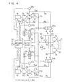
- Fig. 6 shows still another embodiment of the invention in which solenoid-operated valves 24a and 24b are used in place of the pilot-operated valves 21a and 21b shown in Figs. 1 and 2, and the supply of pressure fluid to the control cylinders 13a and 13b for controlling the displacement volume varying means 12a and 12b of the hydraulic pumps 3a and 3b respectively is controlled by operating valves 25a and 25b which in turn are electrically controlled.
- Pressures P5a, P6a, P5b and P6b in the main lines 5a, 6a, 5b and 6b are sensed by pressure sensors 26a, 27a, 26b and 27b respectively.
- Displacements X and X' of the displacement volume varying means 12a and 12b from the neutral position are sensed by displacement sensors 28a and 28b respectively.
- RPMs N and N' of the prime movers la and lb are sensed by RPM sensors 29a and 29b respectively.
- the signals produced by those sensors and a signal representing a manipulated variable X L of an operating lever 30 from the neutral position are inputted to an arithmetic unit 31 which does necessary calculations and supplies control signals to an output device 32.
- the output device 32 Upon receipt of the control signals, the output device 32 supplies commands to the directional control valves 24a and 24b and the operating valves 25a and 25b, to effect control of these valves.
- the arithmetic unit 31 can operate by using an ordinary arithmetic circuit. However, the arithmetic unit 31 will be described as being used with a microcomputer and its operation will be described by referring to a flow chart shown in Fig. 7. The description only refers to the prime mover la, and it is to be understood that the prime mover lb operates in the same manner as the prime mover la. It is also to be understood that when the value of X is positive, pump 3a delivers pressure fluid to the main line 5a and when it is negative, pump 3a delivers pressure fluid to the main line 5b.
- step Sl data X L , P5a, P6a, X and N are read in.
- step S2 When the prime mover la is normally rotating, the process proceeds from step S2 to step S5 in which it is determined whether or not the manipulated variable XL of the lever 30 is essentially zero (0).
- step S6 When X L is zero (0), the process proceeds to step S6; when not zero (0), the process proceeds to step S7.
- step S6 it is determined whether or not the displacement X is essentially zero (0).
- step S3 When X is essentially zero (0), the process proceeds to step S3 and then to step S4.
- step S7 When X is not essentially zero (0), the process proceeds to step S7.
- step S7 it is determined whether or not the value of
- the process proceeds to step S8 in which it is determined whether or not the main line pressures P5a and P6a are higher than preset values.
- step Sll in which it is determined whether or not X L - X is larger than zero (0).
- X L - X > an increment AY corresponding to the main line pressure P5a is read out of the functional relation shown in Fig. 8 which is set previously.
- functions - are preset in such a manner that even if the flow rate of the pressure fluid delivered by the pump 3a is varied by displacing by ⁇ Y the displacement volume varying means 12a, a predetermined allowable highest pressure is not exceeded by the main line pressure P5a or P6a.
- step S14 When X L - X ⁇ 0, in step S14, a decrement -AY of the displacement command Y which would not cause the main line pressure P6a to exceed the predetermined allowable highest pressure is read out of the functional relation shown in Fig. 8.
- the hydraulic pump 3a or 3b connected to the prime mover la or lb not in normal operating condition is shut off the other hydraulic pump and prevented from being forcedly rotated by the pressure fluid delivered by the other hydraulic pump.
- a signal to return the varying means 12a or 12b to a neutral position is supplied to the operating valve 25a or 25b associated with the prime mover not in normal operating condition, so that the varying means 12a or 12b is returned to a neutral position and stops.
- revolution meters 29a and 29b are used as means for sensing whether or not the prime movers la and lb are in normal operating condition.
- the invention is not limited to this specific form of rotation condition sensing means and any other suitable known means, such as means for sensing the output pressure of a prime mover lubricant supply pump, means for sensing the output current of a generator driven by the prime movers, etc.
- the aim of sensing that the flow rate of the pressure fluid delivered by the variable displacement hydraulic pumps 3a and 3b and the command thereto have become essentially zero (0) can be attained by sensing both a control pressure linked to the operating lever and a control pressure associated with the flow rate of the pressure fluid delivered by the pump, such as an output pressure of the neutral position detecting port formed in the servo valve'or an output side pressure of the cut-off valve.
Landscapes
- Engineering & Computer Science (AREA)
- General Engineering & Computer Science (AREA)
- Mechanical Engineering (AREA)
- Mining & Mineral Resources (AREA)
- Civil Engineering (AREA)
- Structural Engineering (AREA)
- Physics & Mathematics (AREA)
- Fluid Mechanics (AREA)
- Operation Control Of Excavators (AREA)
- Fluid-Pressure Circuits (AREA)
Applications Claiming Priority (4)
| Application Number | Priority Date | Filing Date | Title |
|---|---|---|---|
| JP1746881A JPS57134062A (en) | 1981-02-10 | 1981-02-10 | Controller for hydraulic system equipped with plural number of motor |
| JP1746981A JPS57134063A (en) | 1981-02-10 | 1981-02-10 | Controller for hydraulic system equipped with plural number of motor |
| JP17469/81 | 1981-02-10 | ||
| JP17468/81 | 1981-02-10 |
Publications (3)
| Publication Number | Publication Date |
|---|---|
| EP0057930A2 true EP0057930A2 (de) | 1982-08-18 |
| EP0057930A3 EP0057930A3 (en) | 1982-09-01 |
| EP0057930B1 EP0057930B1 (de) | 1985-07-31 |
Family
ID=26353980
Family Applications (1)
| Application Number | Title | Priority Date | Filing Date |
|---|---|---|---|
| EP82100900A Expired EP0057930B1 (de) | 1981-02-10 | 1982-02-08 | Hydraulischer Antrieb mit mehreren Motoren |
Country Status (3)
| Country | Link |
|---|---|
| US (1) | US4561250A (de) |
| EP (1) | EP0057930B1 (de) |
| DE (1) | DE3264974D1 (de) |
Cited By (2)
| Publication number | Priority date | Publication date | Assignee | Title |
|---|---|---|---|---|
| WO1997044535A1 (de) * | 1996-05-22 | 1997-11-27 | Brueninghaus Hydromatik Gmbh | Drehwerksteuerung mit speiseeinrichtung |
| WO1998027287A1 (de) * | 1996-12-19 | 1998-06-25 | O & K Mining Gmbh | Hydraulikschaltung für einen hydraulikbagger |
Families Citing this family (31)
| Publication number | Priority date | Publication date | Assignee | Title |
|---|---|---|---|---|
| CN1010794B (zh) * | 1986-01-11 | 1990-12-12 | 日立建机株式会社 | 液压泵输入功率控制系统 |
| US4780896A (en) * | 1987-02-09 | 1988-10-25 | Siemens Transmission Systems, Inc. | High speed digital counter slip control circuit |
| US4823552A (en) * | 1987-04-29 | 1989-04-25 | Vickers, Incorporated | Failsafe electrohydraulic control system for variable displacement pump |
| US4763487A (en) * | 1987-05-04 | 1988-08-16 | Ralph W. Earl Company, Inc. | Gate control apparatus for refrigerated cargo container |
| US5074495A (en) * | 1987-12-29 | 1991-12-24 | The Boeing Company | Load-adaptive hybrid actuator system and method for actuating control surfaces |
| JP2670815B2 (ja) * | 1988-07-29 | 1997-10-29 | 株式会社小松製作所 | 建設機械の制御装置 |
| US4884401A (en) * | 1988-08-30 | 1989-12-05 | Sundstrand Corp. | Three position dual failure shut-off valve system |
| EP0469451B1 (de) * | 1990-07-25 | 1997-02-05 | CLARK-HURTH COMPONENTS S.p.A. | Getriebe mit drei parallelen Wellen, insbesondere für Nutzfahrzeuge |
| IT1245204B (it) * | 1991-03-15 | 1994-09-13 | Fritz Carl Anton Hurth | Cambio di velocita' a motori idrostatici particolarmente per macchine movimento terra |
| US5160245A (en) * | 1991-05-01 | 1992-11-03 | Sauer, Inc. | Displacement control feedback apparatus and method |
| DE4319280C1 (de) * | 1993-06-09 | 1994-03-03 | Hydromatik Gmbh | Hydrostatischer Fahrantrieb |
| WO1998037346A1 (en) * | 1997-02-21 | 1998-08-27 | Hydril Company | Bi-directional rotary output actuator |
| FR2787528B1 (fr) * | 1998-12-17 | 2001-07-13 | Deboffles Pere Et Fils Atelier | Systeme d'alimentation fluidique et machine agricole equipee d'un tel systeme |
| US7374005B2 (en) * | 2000-01-10 | 2008-05-20 | The United States Of America As Represented By The Administrator Of The U.S. Environmental Protection Agency | Opposing pump/motors |
| US6719080B1 (en) * | 2000-01-10 | 2004-04-13 | The United States Of America As Represented By The Administrator Of The Environmental Protection Agency | Hydraulic hybrid vehicle |
| US7337869B2 (en) | 2000-01-10 | 2008-03-04 | The United States Of America As Represented By The Administrator Of The United States Environmental Protection Agency | Hydraulic hybrid vehicle with integrated hydraulic drive module and four-wheel-drive, and method of operation thereof |
| DE10110935C1 (de) * | 2001-01-23 | 2002-11-28 | Brueninghaus Hydromatik Gmbh | Hydraulische Steuerung, insbesondere zum Ansteuern des Drehwerks eines Baggers |
| US6684636B2 (en) | 2001-10-26 | 2004-02-03 | Caterpillar Inc | Electro-hydraulic pump control system |
| US6848254B2 (en) * | 2003-06-30 | 2005-02-01 | Caterpillar Inc. | Method and apparatus for controlling a hydraulic motor |
| US7243755B2 (en) * | 2004-07-28 | 2007-07-17 | Zf Friedrichshafen Ag | Drive mechanism for a mobile vehicle |
| DE102004044510A1 (de) * | 2004-09-15 | 2006-03-30 | Zf Friedrichshafen Ag | Hydraulisches Getriebe |
| KR101151562B1 (ko) * | 2004-12-29 | 2012-05-30 | 두산인프라코어 주식회사 | 휠로더의 유압펌프 제어장치 |
| JP2006292141A (ja) * | 2005-04-14 | 2006-10-26 | Kanzaki Kokyukoki Mfg Co Ltd | 油圧ポンプユニット及び作業車輌 |
| US8024925B2 (en) * | 2005-11-08 | 2011-09-27 | Caterpillar Inc. | Apparatus, system, and method for controlling a desired torque output |
| US8165765B2 (en) | 2010-05-28 | 2012-04-24 | Caterpillar Inc. | Variator pressure-set torque control |
| US8911216B2 (en) * | 2011-05-06 | 2014-12-16 | Caterpillar Inc. | Method, apparatus, and computer-readable storage medium for controlling torque load of multiple variable displacement hydraulic pumps |
| US8935009B2 (en) * | 2011-05-06 | 2015-01-13 | Caterpillar Inc. | Method and apparatus for controlling multiple variable displacement hydraulic pumps |
| WO2013025416A2 (en) * | 2011-08-12 | 2013-02-21 | Eaton Corporation | Method and apparatus for recovering inertial energy |
| US8850910B1 (en) * | 2011-12-07 | 2014-10-07 | Conrad Ten Have | Shifting of transmission power ratio and power generation for mixer or shredder without power interruption |
| JP5192601B1 (ja) * | 2012-08-20 | 2013-05-08 | 株式会社小松製作所 | 作業車両及び作業車両の制御方法 |
| US9803749B2 (en) | 2015-08-05 | 2017-10-31 | Caterpillar Inc. | Hydraulically coupled multi-variator actuator |
Family Cites Families (7)
| Publication number | Priority date | Publication date | Assignee | Title |
|---|---|---|---|---|
| US3149464A (en) * | 1961-10-31 | 1964-09-22 | Richier Sa | Hydraulic devices for synchronizing the hydraulic motors associated with the wheels of a vehicle |
| GB1105683A (en) * | 1965-11-02 | 1968-03-13 | Anderson Mavor Ltd | Improvements in fluid pressure drive systems for mineral mining machines |
| NL6515645A (de) * | 1965-12-02 | 1967-06-05 | ||
| US3948049A (en) * | 1975-05-01 | 1976-04-06 | Caterpillar Tractor Co. | Dual motor hydrostatic drive system |
| JPS5847328Y2 (ja) * | 1979-04-27 | 1983-10-28 | 株式会社小松製作所 | 油圧駆動車の制御装置 |
| US4345436A (en) * | 1980-04-07 | 1982-08-24 | Caterpillar Tractor Co. | Control for load sharing pumps |
| US4384455A (en) * | 1980-08-11 | 1983-05-24 | Sperry Corporation | Hydraulic motor bypass apparatus |
-
1982
- 1982-02-05 US US06/346,249 patent/US4561250A/en not_active Expired - Fee Related
- 1982-02-08 EP EP82100900A patent/EP0057930B1/de not_active Expired
- 1982-02-08 DE DE8282100900T patent/DE3264974D1/de not_active Expired
Cited By (4)
| Publication number | Priority date | Publication date | Assignee | Title |
|---|---|---|---|---|
| WO1997044535A1 (de) * | 1996-05-22 | 1997-11-27 | Brueninghaus Hydromatik Gmbh | Drehwerksteuerung mit speiseeinrichtung |
| US6167702B1 (en) | 1996-05-22 | 2001-01-02 | Brueninghaus Hydromatik Gmbh | Rotary mechanism control with power supply |
| WO1998027287A1 (de) * | 1996-12-19 | 1998-06-25 | O & K Mining Gmbh | Hydraulikschaltung für einen hydraulikbagger |
| US6996979B1 (en) | 1996-12-19 | 2006-02-14 | Terex / O&K Gmbh | Hydraulic circuit for a hydraulic excavator |
Also Published As
| Publication number | Publication date |
|---|---|
| EP0057930B1 (de) | 1985-07-31 |
| US4561250A (en) | 1985-12-31 |
| EP0057930A3 (en) | 1982-09-01 |
| DE3264974D1 (en) | 1985-09-05 |
Similar Documents
| Publication | Publication Date | Title |
|---|---|---|
| EP0057930B1 (de) | Hydraulischer Antrieb mit mehreren Motoren | |
| US5285642A (en) | Load sensing control system for hydraulic machine | |
| US4475442A (en) | Power transmission | |
| US5873245A (en) | Hydraulic drive system | |
| US4600364A (en) | Fluid operated pump displacement control system | |
| US4480527A (en) | Power transmission | |
| EP0681106A1 (de) | Hydraulische vorrichtung für ein arbeitsgerät | |
| US4407122A (en) | Power transmission | |
| JPH10184615A (ja) | アクチュエータの戻り圧油回収装置 | |
| US4571941A (en) | Hydraulic power system | |
| JP2618396B2 (ja) | 油圧制御システム | |
| JPH0792088B2 (ja) | 土工機械の作動部材に対する水圧制御回路 | |
| EP0068197B1 (de) | Sperrvorrichtung für hydraulischen Kreislauf eines Trägheitsmassenantriebs | |
| US5101629A (en) | Hydraulic circuit system for working machine | |
| US4464898A (en) | Hydraulic power system | |
| EP0056865B1 (de) | Hydraulische Triebvorrichtung | |
| US4353289A (en) | Power transmission | |
| EP1088995A1 (de) | Hydraulische schaltungsanordnung | |
| EP0111208A1 (de) | Getriebe | |
| US4611527A (en) | Power transmission | |
| JPH06123302A (ja) | 建設機械の油圧制御装置 | |
| US4107924A (en) | Pump upgrading system | |
| US4043125A (en) | Fluid system | |
| US4017218A (en) | Dual-speed setting underspeed system | |
| JP3047078B2 (ja) | ロードセンシングシステムにおけるエンジンの自動調速装置 |
Legal Events
| Date | Code | Title | Description |
|---|---|---|---|
| PUAI | Public reference made under article 153(3) epc to a published international application that has entered the european phase |
Free format text: ORIGINAL CODE: 0009012 |
|
| PUAL | Search report despatched |
Free format text: ORIGINAL CODE: 0009013 |
|
| AK | Designated contracting states |
Designated state(s): DE FR |
|
| AK | Designated contracting states |
Designated state(s): DE FR |
|
| 17P | Request for examination filed |
Effective date: 19830128 |
|
| GRAA | (expected) grant |
Free format text: ORIGINAL CODE: 0009210 |
|
| AK | Designated contracting states |
Designated state(s): DE FR |
|
| REF | Corresponds to: |
Ref document number: 3264974 Country of ref document: DE Date of ref document: 19850905 |
|
| ET | Fr: translation filed | ||
| PLBE | No opposition filed within time limit |
Free format text: ORIGINAL CODE: 0009261 |
|
| STAA | Information on the status of an ep patent application or granted ep patent |
Free format text: STATUS: NO OPPOSITION FILED WITHIN TIME LIMIT |
|
| 26N | No opposition filed | ||
| PGFP | Annual fee paid to national office [announced via postgrant information from national office to epo] |
Ref country code: FR Payment date: 19931220 Year of fee payment: 13 |
|
| PGFP | Annual fee paid to national office [announced via postgrant information from national office to epo] |
Ref country code: DE Payment date: 19940428 Year of fee payment: 13 |
|
| PG25 | Lapsed in a contracting state [announced via postgrant information from national office to epo] |
Ref country code: FR Effective date: 19951031 |
|
| PG25 | Lapsed in a contracting state [announced via postgrant information from national office to epo] |
Ref country code: DE Effective date: 19951101 |
|
| REG | Reference to a national code |
Ref country code: FR Ref legal event code: ST |