EP0057766A2 - Elektromagnetischer Sensor - Google Patents
Elektromagnetischer Sensor Download PDFInfo
- Publication number
- EP0057766A2 EP0057766A2 EP81109855A EP81109855A EP0057766A2 EP 0057766 A2 EP0057766 A2 EP 0057766A2 EP 81109855 A EP81109855 A EP 81109855A EP 81109855 A EP81109855 A EP 81109855A EP 0057766 A2 EP0057766 A2 EP 0057766A2
- Authority
- EP
- European Patent Office
- Prior art keywords
- magneto
- substrate
- transducer
- resistor
- circuit
- Prior art date
- Legal status (The legal status is an assumption and is not a legal conclusion. Google has not performed a legal analysis and makes no representation as to the accuracy of the status listed.)
- Withdrawn
Links
Images


Classifications
-
- G—PHYSICS
- G01—MEASURING; TESTING
- G01D—MEASURING NOT SPECIALLY ADAPTED FOR A SPECIFIC VARIABLE; ARRANGEMENTS FOR MEASURING TWO OR MORE VARIABLES NOT COVERED IN A SINGLE OTHER SUBCLASS; TARIFF METERING APPARATUS; MEASURING OR TESTING NOT OTHERWISE PROVIDED FOR
- G01D5/00—Mechanical means for transferring the output of a sensing member; Means for converting the output of a sensing member to another variable where the form or nature of the sensing member does not constrain the means for converting; Transducers not specially adapted for a specific variable
- G01D5/12—Mechanical means for transferring the output of a sensing member; Means for converting the output of a sensing member to another variable where the form or nature of the sensing member does not constrain the means for converting; Transducers not specially adapted for a specific variable using electric or magnetic means
- G01D5/14—Mechanical means for transferring the output of a sensing member; Means for converting the output of a sensing member to another variable where the form or nature of the sensing member does not constrain the means for converting; Transducers not specially adapted for a specific variable using electric or magnetic means influencing the magnitude of a current or voltage
- G01D5/142—Mechanical means for transferring the output of a sensing member; Means for converting the output of a sensing member to another variable where the form or nature of the sensing member does not constrain the means for converting; Transducers not specially adapted for a specific variable using electric or magnetic means influencing the magnitude of a current or voltage using Hall-effect devices
- G01D5/147—Mechanical means for transferring the output of a sensing member; Means for converting the output of a sensing member to another variable where the form or nature of the sensing member does not constrain the means for converting; Transducers not specially adapted for a specific variable using electric or magnetic means influencing the magnitude of a current or voltage using Hall-effect devices influenced by the movement of a third element, the position of Hall device and the source of magnetic field being fixed in respect to each other
Definitions
- This invention relates to a magnetoelectrical transducer which generates an electrical output signal indicative of a change in the intensity of a magnetic field.
- the resolution of the rotation sensor can be improved by increasing the number of teeth of the gear of magnetic material which is the object to be sensed, that is, the pitch of the teeth of the gear must be selected to be as small as possible within a limited dimensional range.
- the magneto-resistors themselves must also be designed to be as small as possible in size for inproving the resolution, since the arrangement of the magneto-resistors is closely related to the pitch of the teeth of the gear which is the object to be sensed.
- the output signal from the magneto-resistors has such a tendency that the higher the resalution, the lower is the output signal level.
- the decreased pitch of the teeth of the gear does not provide an appreciable difference between the magnetic flux density at the position of the crest of the teeth of the gear and that at the position of the bottom of the space between the teeth of the gear.
- the resistance value of each of the magneto-resistors shows a smaller change, that is, there is only a smaller change between the resistance value of the magneto-resistor in the position opposite to the tooth crest and that in the position opposite to the bottom land. Therefore, the level of the output signal from the magneto-resistors becomes correspondingly lower. The lowered level of the output signal from the magneto-resistors gives rise to such a problem that the operation of the rotation sensor is easily adversely affected by external noises.
- a magnetoelectrical'transducer comprising magneto-resistor means disposed opposite to ari element of magnetic material arranged for movement relative thereto so that the resistance value of the magneto-resistor means changes in response to a change in the intensity of the magnetic field due to the relative movement of the magnetic element, voltage source means for applying a predetermined voltage across the magneto-resistor means to derive therefrom a first electrical output signal corresponding to the resistance value, circuit means for converting the first electrical signal applied thereto into a second electrical signal having a predetermined waveform and generating such an electrical output signal, and a substrate having the circuit means and the magneto-resistor means integrally mounted thereon.
- a gear-shaped disc 3 or gear of magnetic material such as iron is suitably fixedly supported on a hub 4 which/is fixedly mounted by a set. screw 5 on the shaft 2 of a motor 1 which 'is an object whose rotation is to be sensed. With the rotation of the motor 1, the gear 3 rotates together with the motor shaft 2.
- a pair of magneto-resistors 7, a bias magnet 8 and a waveform shaping circuit 9, which converts or shapes the output signal of simusoidal waveform generated from the magneto-resistor pair 7 into a rectangular waveform to generate an output signal of rectangular waveform, are integrally mounted on a substrate 6 of electrical insulating material.
- the waveform shaping circuit 9 is preferably in the form of a hybrid integrated circuit formed on the insulating substrate 6.
- the substrate 6 is suitably supported on an L-shaped supporting member 10 which is suitably fixed to the motor 1 with a spacer 11 interposed between it and the motor 1.
- Conductors 12 extend from the substrate 6 for supplying the necessary power and transmitting the transducer output signal, and a cover member 13 covers the whole structure of the magnetoelectrical transducer.
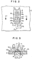
- FIG. 2 is an enlarged schematic plan view of the magneto-resistor pair 7 and associated elements mounted on the substrate 6, when viewed from the side of the gear 3.
- the magneto-resistor pair 7 includes a first magneto-resistor Ml and a second magneto-resistor M 2 .
- the first and second magneto-resistors M 1 and M 2 are electrically connected to each other at one of the ends by a conductor 14a and are electrically connected at the other end to conductors 14b and 14c respectively, thereby constituting a three-terminal magnetic field-intensity sensing structure in which one of the three output terminals is provided by the free end of an extension 14a' extending from the middle portion of the conductor 14a, and the remaining two output terminals are provided by the free ends of the conductors 14b and 14c respectively.
- the conductors 14a, 14b and 14c are electrically connected at the free end to one end of conductors 16a, 16b and 16c respectively, and the conductors 16a, 16b and 16c are electrically connected at the other end to one end of conductors 17a, 17b and 17c respectively.
- the conductors 17a, 17b and 17c are deposited on the substrate 6 and are connected at the other end to the waveform shaping circuit 9 whose structure will be described in detail later.
- the three-terminal magneto-sensing structure is fixedly mounted on one of the pole faces, for example, the N-pole face of the bias magnet 8 to make intimate contact therewith.
- the bias magnet 8 is received in a slot 15 of square shape bored in the substrate 6 and is fixedly supported in the slot 15 of the substrate 6 by being bonded thereto by a bonding agent 18.
- the conductors 17a, 17b and 17c have a very short length on the substrate 6 so that the adverse effect of external noises can be greatly suppressed.
- the waveform shaping circuit 9 is disposed in the form of a hybrid integrated circuit on the substrate 6 as described above, a fine, or miniature conductor pattern can be provided, and the extending length of the conductors can be further shortened, so that the adverse effect of external noises can be more satisfactorily suppressed.
- a ceramic material is commonly used to make a substrate for a hybrid integrated circuit.
- the ceramic material is advantageous over an organic material such as an epoxy resin commonly used as a material of a printed circuit board in that its dielectric constant is smaller than that of such an organic material and it is hardly susceptible to an induction interference from, for example, adjacent signal lines. Therefore, the use of the ceramic material to make the substrate of the transducer of the embodiment according to the present invention exhibits a greater effect in conjunction with the formation of the miniature conductor pattern above described.
- the integral combination of the sensing elements and the waveform shaping circuit in the present invention simplifies greatly the overall construction including the gear of magnetic material which is the object to be sensed, and thus provides numerous merits including the reduced assembling cost and the compact overall size.
- FIG. 4 there is shown a circuit structure including the three-terminal magneto-sensing circuit constitured by the pair of magneto-resistors M 1 and M 2 , and the waveform shaping circuit 9 for shaping the output signal of simusoidal waveform from the magneto-sensing circuit into a rectangular waveform and generating an output signal of rectangular waveform.
- the pair of magneto-resistors M 1 and M 2 are so connected as to constitute a bridge circuit together with a pair of resistors R 1 and R 2 .
- a pair of input terminals Q 1 and Q 2 of the bridge circuit are connected to a voltage source. For example, one input terminal Q 1 of the bridge circuit is connected to a source of voltage Vcc, and the other input terminal Q 2 is grounded.
- a pair of output terminals Q 3 and Q 4 of the bridge circuit are connected to a pair of input terminals respectively of a comparator 19 which constitutes the waveform shaping .
- circuit 9 in combination with the resistors R1 and R 2 in the bridge circuit.
- one output terminal Q 3 is connected through an input resistor R 3 to the positive input terminal of the comparator 19, and the other output terminal Q 4 is directly connected to the negative input terminal of the comparator 19.
- a resistor R 4 acts as a feedback resistor for the comparator 19.
- FIG. 5(a) shows the waveform of the input signal applied to the positive input terminal of the comparator 19, that is, the signal V IN of simusoidal waveform appearing from the output terminal Q 3 of the three-termnal magneto-sensing structure in response to the rotation of the gear 3.
- FIG. 5(a) also shows the level of a reference voltage V REF appearing at the connection point Q 3 between the voltage-dividing resistors R1 and R 2 in the bridge circuit to be applied to the negative input terminal of the comparator 19.
- FIG. 5(b) shows the waveform of the output signal V OUT of rectangular pulse waveform generated from the compartor 19 after being shaped in the waveform.
- the pitch P 1 of the first magneto-resistor M 1 and the second magneto-resistor M 2 is selected to be 1/2 of the pitch P 2 of the teeth of the gear 3. It will be readily understood that the three-terminal magneto-sensing structure provides its maximum output when the ratio between the pitches P I and P 2 is so selected.
- Reference symbol g in FIG. 3 designates the gap between the gear 3.and the first and second magneto-resistors M 1 and M 2 .
- This gap g is generally selected to be not more than 0.2 mm, preferably 0.1 mm, so as to ensure generation of an output signal of highest possible level from the magneto-resistors M 1 and M 2 .
- the resistors R 1 and R 2 in the waveform shaping circuit act as . adjusting resistors determining the level of the reference voltage V REF applied to the negative input terminal of the comparator 19 and are preferably in the form of thick-film resistors deposited on the substrate 6.
- the duty factor t/T of the rectangular waveform V OUT appearing from the output terminal of the comparator 19 when the voltage V IN generated in response to the rotation of the gear 3 is applied to the positive input terminal of the comparator 19 from the connection pint Q 3 between the magneto-resistors M 1 and M 2 constituting the three-terminal magneto-sensing structure and the reference voltage V REF is applied to the neagtive input terminal of the comparator 19, is determined by the level of V IN relative to that of V REF .
- the duty factor, t/T x 100 (%), to be 50%. It will therefore be seen from FIG. 5 that it is necessary to select V REF to be V REF 1 ⁇ 2(V H + V L ).
- the duty factor t/T is such that the relation between the adjusting resistors R 1 and R 2 is previously selected to be, for example, R 1 ⁇ R 2 , and, while rotating the gear 3 in the actually mounted condition of the magnetoelectrical transducer, the resistance value of the adjusting resistor R 1 is gradually increased to adjust the level of the reference voltage V REF until the duty factor of 50% is attained.
- a portion of the thick-film resistor is removed bit by bit.
- the waveform shaping circuit 9 is in the form of a hybrid integrated circuit formed on the substrate 6. From the aspect of the manufacturing cost, all of the components of the circuit 9 are gathered on one of the surfaces of the substrate 6 nearer to the gear 3 than the other, so as to-provide a so-called one-sided hybrid integrated circuit. In this case, consideration is required so that the space 9-1 having disposed therein the components including the comparator 19 occupying a considerable height among those composing the circuit 9, as shown in FIGs. 6 and 7, is located in an area lower than the level of the gear 3 when viewed in FIG. 1, and only the conductors and thick-film resistors including the thick-film adjusting resistor R 1 deposited on the substrate 6 are disposed in the remaining space 9-2. This is because the adjustment of the resistance value of the adjusting resistor R 1 is required after the transducer is mounted in position. Otherwise, the gear 3 will interfere with the adjustment of the resistance value of the resistor R 1 , and the adjustment will become impossible.
- the embodiment of the transducer having such a construction could at least attain the object of the present invention, but the inventors have found the necessity for a further improvement in the proposed construction. More precisely, the inventors have found that, with the construction above described, the difficulty of circuit layout requires a slight increase in the area of the substrate 6, and, in addition, the illustrated thickness H becomes inevitably large resulting in difficultly of miniaturization due to the fact that the space portion underlying the bias magnet 8 having the height h shown in FIG. 7.cannot be effectively utilized. The inventors have further found that, in. the arrangement of FIG. 7, the gear 3 interferes still with the adjustment of the resistance value of the resistor R1 required for the adjustment of the duty factor, and the resistance adjustment requires a considerable length of time even when special tools are used.
- FIGs.. 8 and 9 show another embodiment of the present invention or an improvement in the component arrangement shown in FIGs. 6 and 7.
- the output conductors extending from the pair of magneto-resistors 7 are disposed on one of the surfaces of the substrate 6 nearer to the gear 3 than the other, and all of the components of the waveform shaping circuit 9 and the conductors required for wiring are disposed on the entire area of the other surface 9A of the substrate 6 remote from the gear 3.
- the magneto-resistors 7 disposed on the substrate surface opposite to the gear 3 are electrically connected to the circuit 9 disposed on the other substrate surface 9A by conductors printed on the necessary portions of the surfaces of the substrate 6 or through one or more through-holes bored in the substrate 6 for establishing the electrical connections between the magneto-resistors 7 and the circuit 9, among necessary procedures.
- the entire space 9A, except the space portion occupied by the bias magnet 8, is now available for the circuit 9 thereby simplifying the layout of the circuit 9.
- the height D:of the circuit parts of the circuit 9 would not substantially exceed the height h of the bias magnet 8 which is commonly as high as about 4 mm. Therefore, the thickness H of the actually mounted transducer including the thickness of the substrate 6 can be reduced to about the half of the prior art value, and the volume of the actually mounted transducer can be greatly decreased compared with the prior art one.
- FIGs. 8 and 9 provides such a great additional merit that, because of the fact that the adjusting resistors R 1 and R 2 are also disposed on the surface of the substrate 6 on which the bias magnet 8 is disposed, that is, on the substrate surface remote from the gear 3, the step of function trimming or the step of adjusting the duty ratio while rotating the gear 3 can be very easily and accurately carried out within a short time compared with the prior art step.
- FIG. 10 shows a modification of the circuit structure shown in FIG. 4.
- the comparator 19 is replaced by an amplifier 20, and the output voltage V IN of-the three-terminal magnetic field-intensity sensing structure is applied to one input terminal of the amplifier 20, while the output voltage V REF of the voltage divider is applied through an input resistor R 5 to the other input terminal of the amplifier 20.
- a resistor R 6 is connected across the amplifier 20 to function as a feedback resistor.
- the amplifier 20 acts merely as a signal amplifying means, and its output V OUT has a sinusoidal waveform in.-which the amplitude of the sinusoidal input waveform V IN is amplified to a level determined by a predetermined amplification factor.
- this sinusoidal output waveform V OUT is used for the control of the rotation speed or angular position of rotation of the rotary machine, any detailed description will not be given herein since the manner of control is outside of the scope of the present invention.
- a pair of magneto-resistors are incorporated in the transducer so as to improve the sensitivity of measurement.
- incorporation of only one magneto-resistor to constitute part of a magnetoelectrical transducer and such a magnetoelectrical transducer are also included in the scope of the present invention.
- one of the magneto-resistors for example, the magneto-resistor M 1 in FIG. 4 or FIG. 10 may be replaced by a conventional resistor.
- the upper surface of the magneto-resistors M 1 and M 2 registers substantially with that of the substrate 6 in FIG. 2, the upper surface of the magneto-resistors M1 and M 2 is shown protruding slightly from that of-the substrate 6 in FIG. I in order to clearly illustrate the position of the magneto-resistors. It is preferable from the manufacturing viewpoint that the upper surface of the magneto-resistors M 1 and M 2 registers with that of the substrate 6. However, this is not an essential condition, and the upper surface of the magneto-resistors M 1 and M 2 may slightly protrude from that of the substrate 6 as shown in FIG. 1 without in any way obstructing the primary function of the transducer.
Landscapes
- Physics & Mathematics (AREA)
- General Physics & Mathematics (AREA)
- Transmission And Conversion Of Sensor Element Output (AREA)
- Measuring Magnetic Variables (AREA)
Applications Claiming Priority (4)
| Application Number | Priority Date | Filing Date | Title |
|---|---|---|---|
| JP56016313A JPS57131013A (en) | 1981-02-07 | 1981-02-07 | Magnetic substance detector |
| JP16313/81 | 1981-02-07 | ||
| JP56033969A JPS57148281A (en) | 1981-03-11 | 1981-03-11 | Device for detecting magnetic substance |
| JP33969/81 | 1981-03-11 |
Publications (2)
| Publication Number | Publication Date |
|---|---|
| EP0057766A2 true EP0057766A2 (de) | 1982-08-18 |
| EP0057766A3 EP0057766A3 (de) | 1984-07-18 |
Family
ID=26352632
Family Applications (1)
| Application Number | Title | Priority Date | Filing Date |
|---|---|---|---|
| EP81109855A Withdrawn EP0057766A3 (de) | 1981-02-07 | 1981-11-24 | Elektromagnetischer Sensor |
Country Status (2)
| Country | Link |
|---|---|
| US (1) | US4853632A (de) |
| EP (1) | EP0057766A3 (de) |
Cited By (12)
| Publication number | Priority date | Publication date | Assignee | Title |
|---|---|---|---|---|
| WO1986000877A1 (fr) * | 1984-07-20 | 1986-02-13 | Robert Bosch Gmbh | Detecteur a magnetoresistance pour la production de signaux electriques |
| WO1986000986A1 (fr) * | 1984-07-20 | 1986-02-13 | Robert Bosch Gmbh | Dispositif sensible magnetoresistif pour mesurer des variations du champ magnetique et procede pour le fabriquer |
| EP0201682A1 (de) * | 1985-04-12 | 1986-11-20 | Robert Bosch Gmbh | Integrierter Drehzahlsensor mit magnetfeldabhängigen Sensorwiderständen |
| EP0111866A3 (en) * | 1982-12-13 | 1986-12-30 | Hitachi, Ltd. | Apparatus for magnetically detecting positions |
| EP0188772A3 (de) * | 1984-12-24 | 1988-03-23 | Alcatel SEL Aktiengesellschaft | Positionsgeber |
| EP0188788A3 (de) * | 1984-12-24 | 1988-03-30 | Alcatel N.V. | Magnetfelddetektor |
| EP0243566A3 (de) * | 1985-12-28 | 1988-10-19 | Yamaha Corporation | Magnetischer Messwertgeber der Widerstandsart für Codiergeräte |
| EP0234458A3 (de) * | 1986-02-19 | 1988-12-21 | Alcatel SEL Aktiengesellschaft | Näherungssensor |
| EP0351697A1 (de) * | 1988-07-20 | 1990-01-24 | Deutsche Thomson-Brandt GmbH | Schaltung zur Umwandlung |
| EP0280261A3 (de) * | 1987-02-27 | 1990-05-09 | Alcatel SEL Aktiengesellschaft | Schaltung zur Gewinnung eines temperaturunabhängigen Rechtecksignals aus einem Messsignal |
| EP0233618A3 (de) * | 1986-02-19 | 1990-09-05 | Alcatel SEL Aktiengesellschaft | Bewegungssensor |
| CN102195620A (zh) * | 2010-03-18 | 2011-09-21 | 中国科学院电子学研究所 | 无源宽带时钟输入转换方法及电路 |
Families Citing this family (34)
| Publication number | Priority date | Publication date | Assignee | Title |
|---|---|---|---|---|
| US5237272A (en) * | 1988-10-11 | 1993-08-17 | Mitsubishi Denki K.K. | Magnetic circuit device for a hall effect type sensor for detecting crank angle |
| US5041784A (en) * | 1989-11-16 | 1991-08-20 | Visi-Trak Corporation | Magnetic sensor with rectangular field distorting flux bar |
| DE4020228A1 (de) * | 1990-06-26 | 1992-01-02 | Philips Patentverwaltung | Anordnung zum detektieren eines bewegten ferromagnetischen elements |
| US5045920A (en) * | 1990-06-28 | 1991-09-03 | Allegro Microsystems, Inc. | Dual-Hall ferrous-article-proximity sensor |
| US5038130A (en) * | 1990-11-06 | 1991-08-06 | Santa Barbara Research Center | System for sensing changes in a magnetic field |
| US5293125A (en) * | 1992-01-17 | 1994-03-08 | Lake Shore Cryotronics, Inc. | Self-aligning tachometer with interchangeable elements for different resolution outputs |
| US5304926A (en) * | 1992-04-08 | 1994-04-19 | Honeywell Inc. | Geartooth position sensor with two hall effect elements |
| US5291133A (en) * | 1992-08-24 | 1994-03-01 | General Motors Corporation | Multi-bit encoder signal conditioning circuit having common mode disturbance compensation |
| US5341097A (en) * | 1992-09-29 | 1994-08-23 | Honeywell Inc. | Asymmetrical magnetic position detector |
| US5336994A (en) * | 1992-11-20 | 1994-08-09 | Lake Shore Cryotronics, Inc. | Magneto-resistive tachometer assembly with reversible cover and related method |
| DE4341890C2 (de) * | 1992-12-09 | 2003-11-06 | Denso Corp | Magnetische Detektionseinrichtung |
| US5469054A (en) * | 1993-04-22 | 1995-11-21 | Honeywell Inc. | Position sensor with two magnetically sensitive devices and two target tracks which are sensed in combination with each other to provide a synthesized signal |
| US5351028A (en) * | 1993-06-14 | 1994-09-27 | Honeywell Inc. | Magnetoresistive proximity sensor |
| US5495758A (en) * | 1993-06-17 | 1996-03-05 | Lake Shore Cryotronics, Inc. | Tachometer assembly with integral internal wrench |
| US5477143A (en) * | 1994-01-11 | 1995-12-19 | Honeywell Inc. | Sensor with magnetoresistors disposed on a plane which is parallel to and displaced from the magnetic axis of a permanent magnet |
| US5644226A (en) * | 1994-03-02 | 1997-07-01 | Nippondenso Co., Ltd. | Magnetic detector having a bias magnet and magnetoresistive elements shifted away from the center of the magnet |
| US5514955A (en) * | 1994-03-11 | 1996-05-07 | Lake Shore Cryotronics, Inc. | Slim profile digital tachometer including planar block and rotor having spokes and clamp |
| JP3368681B2 (ja) * | 1994-09-13 | 2003-01-20 | 株式会社デンソー | 磁気検出装置 |
| US6246233B1 (en) | 1994-12-30 | 2001-06-12 | Northstar Technologies Inc. | Magnetoresistive sensor with reduced output signal jitter and temperature compensation |
| US5500589A (en) * | 1995-01-18 | 1996-03-19 | Honeywell Inc. | Method for calibrating a sensor by moving a magnet while monitoring an output signal from a magnetically sensitive component |
| US5488294A (en) * | 1995-01-18 | 1996-01-30 | Honeywell Inc. | Magnetic sensor with means for retaining a magnet at a precise calibrated position |
| JP2982638B2 (ja) * | 1995-01-19 | 1999-11-29 | 株式会社デンソー | 変位検出装置 |
| JPH09329463A (ja) * | 1996-06-10 | 1997-12-22 | Mitsubishi Electric Corp | 検出装置 |
| DE19628566A1 (de) * | 1996-07-16 | 1998-01-29 | Bosch Gmbh Robert | Magnetfeldempfindlicher Sensor |
| JP3404249B2 (ja) * | 1997-03-26 | 2003-05-06 | 三菱電機株式会社 | 磁気センサ |
| DE19846078B4 (de) * | 1997-10-10 | 2005-05-19 | Leopold Kostal Gmbh & Co Kg | Elektronische Einrichtung |
| JP3941082B2 (ja) | 1998-01-28 | 2007-07-04 | 株式会社安川電機 | 磁気式検出器 |
| JPH11304414A (ja) * | 1998-04-21 | 1999-11-05 | Mitsubishi Electric Corp | 磁気検出装置 |
| JP3544141B2 (ja) * | 1998-05-13 | 2004-07-21 | 三菱電機株式会社 | 磁気検出素子および磁気検出装置 |
| JP3615468B2 (ja) * | 2000-07-06 | 2005-02-02 | ヒロセ電機株式会社 | パルス信号発生装置 |
| US6798193B2 (en) * | 2002-08-14 | 2004-09-28 | Honeywell International Inc. | Calibrated, low-profile magnetic sensor |
| ATE402396T1 (de) * | 2002-10-10 | 2008-08-15 | Ebm Papst St Georgen Gmbh & Co | Vorrichtung zum erfassen des absolutwinkels einer welle |
| JP3781422B2 (ja) * | 2003-08-19 | 2006-05-31 | 株式会社ミネルバ | 磁気センサ |
| DE102019212757A1 (de) * | 2019-08-26 | 2021-03-04 | Robert Bosch Gmbh | Schaltungsanordnung zum Wandeln eines Eingangssignals in ein rechteckförmi-ges Ausgangssignal |
Family Cites Families (6)
| Publication number | Priority date | Publication date | Assignee | Title |
|---|---|---|---|---|
| US3800193A (en) * | 1972-09-05 | 1974-03-26 | Ibm | Magnetic sensing device |
| US3846697A (en) * | 1972-11-14 | 1974-11-05 | Airpax Electronics | Digital pickup |
| US3816766A (en) * | 1973-01-29 | 1974-06-11 | Sprague Electric Co | Integrated circuit with hall cell |
| US3916428A (en) * | 1973-05-19 | 1975-10-28 | Matsushita Electric Industrial Co Ltd | Semiconductor magneto-resistance element |
| DE2606845B2 (de) * | 1976-02-20 | 1980-01-10 | Wabco Fahrzeugbremsen Gmbh, 3000 Hannover | Vorrichtung zur Überwachung der Bewegung des Rades eines Fahrzeugs |
| US4262526A (en) * | 1978-07-21 | 1981-04-21 | Nippondenso Co., Ltd. | Rotational position detecting apparatus |
-
1981
- 1981-11-24 US US06/324,669 patent/US4853632A/en not_active Expired - Lifetime
- 1981-11-24 EP EP81109855A patent/EP0057766A3/de not_active Withdrawn
Cited By (14)
| Publication number | Priority date | Publication date | Assignee | Title |
|---|---|---|---|---|
| EP0111866A3 (en) * | 1982-12-13 | 1986-12-30 | Hitachi, Ltd. | Apparatus for magnetically detecting positions |
| WO1986000877A1 (fr) * | 1984-07-20 | 1986-02-13 | Robert Bosch Gmbh | Detecteur a magnetoresistance pour la production de signaux electriques |
| WO1986000986A1 (fr) * | 1984-07-20 | 1986-02-13 | Robert Bosch Gmbh | Dispositif sensible magnetoresistif pour mesurer des variations du champ magnetique et procede pour le fabriquer |
| EP0188772A3 (de) * | 1984-12-24 | 1988-03-23 | Alcatel SEL Aktiengesellschaft | Positionsgeber |
| EP0188788A3 (de) * | 1984-12-24 | 1988-03-30 | Alcatel N.V. | Magnetfelddetektor |
| EP0201682A1 (de) * | 1985-04-12 | 1986-11-20 | Robert Bosch Gmbh | Integrierter Drehzahlsensor mit magnetfeldabhängigen Sensorwiderständen |
| EP0243566A3 (de) * | 1985-12-28 | 1988-10-19 | Yamaha Corporation | Magnetischer Messwertgeber der Widerstandsart für Codiergeräte |
| EP0234458A3 (de) * | 1986-02-19 | 1988-12-21 | Alcatel SEL Aktiengesellschaft | Näherungssensor |
| EP0233618A3 (de) * | 1986-02-19 | 1990-09-05 | Alcatel SEL Aktiengesellschaft | Bewegungssensor |
| EP0280261A3 (de) * | 1987-02-27 | 1990-05-09 | Alcatel SEL Aktiengesellschaft | Schaltung zur Gewinnung eines temperaturunabhängigen Rechtecksignals aus einem Messsignal |
| EP0351697A1 (de) * | 1988-07-20 | 1990-01-24 | Deutsche Thomson-Brandt GmbH | Schaltung zur Umwandlung |
| WO1990001233A1 (de) * | 1988-07-20 | 1990-02-08 | Deutsche Thomson-Brandt Gmbh | Schaltung zur umwandlung |
| US5315260A (en) * | 1988-07-20 | 1994-05-24 | Deutsche Thomson-Brandt Gmbh | Apparatus for converting an AC component of a signal to a square wave |
| CN102195620A (zh) * | 2010-03-18 | 2011-09-21 | 中国科学院电子学研究所 | 无源宽带时钟输入转换方法及电路 |
Also Published As
| Publication number | Publication date |
|---|---|
| US4853632A (en) | 1989-08-01 |
| EP0057766A3 (de) | 1984-07-18 |
Similar Documents
| Publication | Publication Date | Title |
|---|---|---|
| EP0057766A2 (de) | Elektromagnetischer Sensor | |
| US4853604A (en) | Position and speed sensors | |
| US8421446B2 (en) | Position encoder and a method for detecting the position of a movable part of a machine | |
| JP4253198B2 (ja) | 誘導電流式位置変換器 | |
| JP3596850B2 (ja) | マルチタップ受信器捲線を有する誘導性位置トランスデューサ及び相対位置を判別するための方法 | |
| USRE34355E (en) | Magneto resistive sensor for detecting movement of a rotating body | |
| EP0586023A2 (de) | Kapazitives System zum Positionsgeben | |
| US5592079A (en) | Microelectronic position sensor for volume control | |
| US6922051B2 (en) | Displacement and/or angle sensor with a meander-shaped measuring winding | |
| US6417587B1 (en) | Motor | |
| EP0407020B1 (de) | Elektrostatische Winkelmessvorrichtung | |
| US4477810A (en) | Capacity type rotation detecting apparatus | |
| US4713613A (en) | Device for magnetically detecting displacement of non-magnetic movable member | |
| US4418347A (en) | Rotational position detecting apparatus | |
| Kennel | New developments in capacitive encoders for servo drives | |
| EP2038616B1 (de) | Positionskodierer und verfahren zum detektieren der position eines beweglichen teils einer maschine | |
| JP4054693B2 (ja) | 静電容量式変位測定器 | |
| US6566861B2 (en) | Pulse signal generator | |
| JPH0641863B2 (ja) | 流量発信器 | |
| JPH0714905Y2 (ja) | 設定値設定装置 | |
| JPH0714906Y2 (ja) | クロスコイル形指示計器 | |
| EP1310771A1 (de) | Impulssignalgenerator | |
| JP2627354B2 (ja) | 磁気センサと磁気ロータリエンコーダ | |
| JPH0558126B2 (de) | ||
| JP5865329B2 (ja) | エンコーダ |
Legal Events
| Date | Code | Title | Description |
|---|---|---|---|
| PUAI | Public reference made under article 153(3) epc to a published international application that has entered the european phase |
Free format text: ORIGINAL CODE: 0009012 |
|
| AK | Designated contracting states |
Designated state(s): BE CH DE FR GB IT LI NL SE |
|
| PUAL | Search report despatched |
Free format text: ORIGINAL CODE: 0009013 |
|
| AK | Designated contracting states |
Designated state(s): BE CH DE FR GB IT LI NL SE |
|
| 17P | Request for examination filed |
Effective date: 19840723 |
|
| STAA | Information on the status of an ep patent application or granted ep patent |
Free format text: STATUS: THE APPLICATION HAS BEEN WITHDRAWN |
|
| 18W | Application withdrawn |
Withdrawal date: 19860318 |
|
| RIN1 | Information on inventor provided before grant (corrected) |
Inventor name: SEKIZAWA, SADAO Inventor name: NAGANO, YOOSUKE Inventor name: SEKI, TOSHIO |