EP0057545A2 - Vorrichtung zur Anwendung von Strahlungsenergie - Google Patents
Vorrichtung zur Anwendung von Strahlungsenergie Download PDFInfo
- Publication number
- EP0057545A2 EP0057545A2 EP82300347A EP82300347A EP0057545A2 EP 0057545 A2 EP0057545 A2 EP 0057545A2 EP 82300347 A EP82300347 A EP 82300347A EP 82300347 A EP82300347 A EP 82300347A EP 0057545 A2 EP0057545 A2 EP 0057545A2
- Authority
- EP
- European Patent Office
- Prior art keywords
- diaphragm
- photocell
- source
- filament
- radiant
- Prior art date
- Legal status (The legal status is an assumption and is not a legal conclusion. Google has not performed a legal analysis and makes no representation as to the accuracy of the status listed.)
- Granted
Links
Images


Classifications
-
- B—PERFORMING OPERATIONS; TRANSPORTING
- B29—WORKING OF PLASTICS; WORKING OF SUBSTANCES IN A PLASTIC STATE IN GENERAL
- B29C—SHAPING OR JOINING OF PLASTICS; SHAPING OF MATERIAL IN A PLASTIC STATE, NOT OTHERWISE PROVIDED FOR; AFTER-TREATMENT OF THE SHAPED PRODUCTS, e.g. REPAIRING
- B29C65/00—Joining or sealing of preformed parts, e.g. welding of plastics materials; Apparatus therefor
- B29C65/02—Joining or sealing of preformed parts, e.g. welding of plastics materials; Apparatus therefor by heating, with or without pressure
- B29C65/14—Joining or sealing of preformed parts, e.g. welding of plastics materials; Apparatus therefor by heating, with or without pressure using wave energy, i.e. electromagnetic radiation, or particle radiation
- B29C65/1429—Joining or sealing of preformed parts, e.g. welding of plastics materials; Apparatus therefor by heating, with or without pressure using wave energy, i.e. electromagnetic radiation, or particle radiation characterised by the way of heating the interface
- B29C65/1435—Joining or sealing of preformed parts, e.g. welding of plastics materials; Apparatus therefor by heating, with or without pressure using wave energy, i.e. electromagnetic radiation, or particle radiation characterised by the way of heating the interface at least passing through one of the parts to be joined, i.e. transmission welding
- B29C65/1438—Joining or sealing of preformed parts, e.g. welding of plastics materials; Apparatus therefor by heating, with or without pressure using wave energy, i.e. electromagnetic radiation, or particle radiation characterised by the way of heating the interface at least passing through one of the parts to be joined, i.e. transmission welding focusing the wave energy or particle radiation on the interface
-
- A—HUMAN NECESSITIES
- A61—MEDICAL OR VETERINARY SCIENCE; HYGIENE
- A61J—CONTAINERS SPECIALLY ADAPTED FOR MEDICAL OR PHARMACEUTICAL PURPOSES; DEVICES OR METHODS SPECIALLY ADAPTED FOR BRINGING PHARMACEUTICAL PRODUCTS INTO PARTICULAR PHYSICAL OR ADMINISTERING FORMS; DEVICES FOR ADMINISTERING FOOD OR MEDICINES ORALLY; BABY COMFORTERS; DEVICES FOR RECEIVING SPITTLE
- A61J1/00—Containers specially adapted for medical or pharmaceutical purposes
-
- B—PERFORMING OPERATIONS; TRANSPORTING
- B29—WORKING OF PLASTICS; WORKING OF SUBSTANCES IN A PLASTIC STATE IN GENERAL
- B29C—SHAPING OR JOINING OF PLASTICS; SHAPING OF MATERIAL IN A PLASTIC STATE, NOT OTHERWISE PROVIDED FOR; AFTER-TREATMENT OF THE SHAPED PRODUCTS, e.g. REPAIRING
- B29C65/00—Joining or sealing of preformed parts, e.g. welding of plastics materials; Apparatus therefor
- B29C65/02—Joining or sealing of preformed parts, e.g. welding of plastics materials; Apparatus therefor by heating, with or without pressure
- B29C65/14—Joining or sealing of preformed parts, e.g. welding of plastics materials; Apparatus therefor by heating, with or without pressure using wave energy, i.e. electromagnetic radiation, or particle radiation
- B29C65/1429—Joining or sealing of preformed parts, e.g. welding of plastics materials; Apparatus therefor by heating, with or without pressure using wave energy, i.e. electromagnetic radiation, or particle radiation characterised by the way of heating the interface
- B29C65/1445—Joining or sealing of preformed parts, e.g. welding of plastics materials; Apparatus therefor by heating, with or without pressure using wave energy, i.e. electromagnetic radiation, or particle radiation characterised by the way of heating the interface heating both sides of the joint
-
- B—PERFORMING OPERATIONS; TRANSPORTING
- B29—WORKING OF PLASTICS; WORKING OF SUBSTANCES IN A PLASTIC STATE IN GENERAL
- B29C—SHAPING OR JOINING OF PLASTICS; SHAPING OF MATERIAL IN A PLASTIC STATE, NOT OTHERWISE PROVIDED FOR; AFTER-TREATMENT OF THE SHAPED PRODUCTS, e.g. REPAIRING
- B29C65/00—Joining or sealing of preformed parts, e.g. welding of plastics materials; Apparatus therefor
- B29C65/02—Joining or sealing of preformed parts, e.g. welding of plastics materials; Apparatus therefor by heating, with or without pressure
- B29C65/14—Joining or sealing of preformed parts, e.g. welding of plastics materials; Apparatus therefor by heating, with or without pressure using wave energy, i.e. electromagnetic radiation, or particle radiation
- B29C65/1429—Joining or sealing of preformed parts, e.g. welding of plastics materials; Apparatus therefor by heating, with or without pressure using wave energy, i.e. electromagnetic radiation, or particle radiation characterised by the way of heating the interface
- B29C65/1464—Joining or sealing of preformed parts, e.g. welding of plastics materials; Apparatus therefor by heating, with or without pressure using wave energy, i.e. electromagnetic radiation, or particle radiation characterised by the way of heating the interface making use of several radiators
- B29C65/1467—Joining or sealing of preformed parts, e.g. welding of plastics materials; Apparatus therefor by heating, with or without pressure using wave energy, i.e. electromagnetic radiation, or particle radiation characterised by the way of heating the interface making use of several radiators at the same time, i.e. simultaneous welding
-
- B—PERFORMING OPERATIONS; TRANSPORTING
- B29—WORKING OF PLASTICS; WORKING OF SUBSTANCES IN A PLASTIC STATE IN GENERAL
- B29C—SHAPING OR JOINING OF PLASTICS; SHAPING OF MATERIAL IN A PLASTIC STATE, NOT OTHERWISE PROVIDED FOR; AFTER-TREATMENT OF THE SHAPED PRODUCTS, e.g. REPAIRING
- B29C65/00—Joining or sealing of preformed parts, e.g. welding of plastics materials; Apparatus therefor
- B29C65/02—Joining or sealing of preformed parts, e.g. welding of plastics materials; Apparatus therefor by heating, with or without pressure
- B29C65/14—Joining or sealing of preformed parts, e.g. welding of plastics materials; Apparatus therefor by heating, with or without pressure using wave energy, i.e. electromagnetic radiation, or particle radiation
- B29C65/1477—Joining or sealing of preformed parts, e.g. welding of plastics materials; Apparatus therefor by heating, with or without pressure using wave energy, i.e. electromagnetic radiation, or particle radiation making use of an absorber or impact modifier
- B29C65/148—Joining or sealing of preformed parts, e.g. welding of plastics materials; Apparatus therefor by heating, with or without pressure using wave energy, i.e. electromagnetic radiation, or particle radiation making use of an absorber or impact modifier placed at the interface
-
- B—PERFORMING OPERATIONS; TRANSPORTING
- B29—WORKING OF PLASTICS; WORKING OF SUBSTANCES IN A PLASTIC STATE IN GENERAL
- B29C—SHAPING OR JOINING OF PLASTICS; SHAPING OF MATERIAL IN A PLASTIC STATE, NOT OTHERWISE PROVIDED FOR; AFTER-TREATMENT OF THE SHAPED PRODUCTS, e.g. REPAIRING
- B29C65/00—Joining or sealing of preformed parts, e.g. welding of plastics materials; Apparatus therefor
- B29C65/56—Joining or sealing of preformed parts, e.g. welding of plastics materials; Apparatus therefor using mechanical means or mechanical connections, e.g. form-fits
- B29C65/58—Snap connection
-
- B—PERFORMING OPERATIONS; TRANSPORTING
- B29—WORKING OF PLASTICS; WORKING OF SUBSTANCES IN A PLASTIC STATE IN GENERAL
- B29C—SHAPING OR JOINING OF PLASTICS; SHAPING OF MATERIAL IN A PLASTIC STATE, NOT OTHERWISE PROVIDED FOR; AFTER-TREATMENT OF THE SHAPED PRODUCTS, e.g. REPAIRING
- B29C65/00—Joining or sealing of preformed parts, e.g. welding of plastics materials; Apparatus therefor
- B29C65/72—Joining or sealing of preformed parts, e.g. welding of plastics materials; Apparatus therefor by combined operations or combined techniques, e.g. welding and stitching
-
- B—PERFORMING OPERATIONS; TRANSPORTING
- B29—WORKING OF PLASTICS; WORKING OF SUBSTANCES IN A PLASTIC STATE IN GENERAL
- B29C—SHAPING OR JOINING OF PLASTICS; SHAPING OF MATERIAL IN A PLASTIC STATE, NOT OTHERWISE PROVIDED FOR; AFTER-TREATMENT OF THE SHAPED PRODUCTS, e.g. REPAIRING
- B29C65/00—Joining or sealing of preformed parts, e.g. welding of plastics materials; Apparatus therefor
- B29C65/74—Joining or sealing of preformed parts, e.g. welding of plastics materials; Apparatus therefor by welding and severing, or by joining and severing, the severing being performed in the area to be joined, next to the area to be joined, in the joint area or next to the joint area
- B29C65/747—Joining or sealing of preformed parts, e.g. welding of plastics materials; Apparatus therefor by welding and severing, or by joining and severing, the severing being performed in the area to be joined, next to the area to be joined, in the joint area or next to the joint area using other than mechanical means
- B29C65/7473—Joining or sealing of preformed parts, e.g. welding of plastics materials; Apparatus therefor by welding and severing, or by joining and severing, the severing being performed in the area to be joined, next to the area to be joined, in the joint area or next to the joint area using other than mechanical means using radiation, e.g. laser, for simultaneously welding and severing
-
- B—PERFORMING OPERATIONS; TRANSPORTING
- B29—WORKING OF PLASTICS; WORKING OF SUBSTANCES IN A PLASTIC STATE IN GENERAL
- B29C—SHAPING OR JOINING OF PLASTICS; SHAPING OF MATERIAL IN A PLASTIC STATE, NOT OTHERWISE PROVIDED FOR; AFTER-TREATMENT OF THE SHAPED PRODUCTS, e.g. REPAIRING
- B29C66/00—General aspects of processes or apparatus for joining preformed parts
- B29C66/01—General aspects dealing with the joint area or with the area to be joined
- B29C66/05—Particular design of joint configurations
- B29C66/10—Particular design of joint configurations particular design of the joint cross-sections
- B29C66/11—Joint cross-sections comprising a single joint-segment, i.e. one of the parts to be joined comprising a single joint-segment in the joint cross-section
- B29C66/112—Single lapped joints
- B29C66/1122—Single lap to lap joints, i.e. overlap joints
-
- B—PERFORMING OPERATIONS; TRANSPORTING
- B29—WORKING OF PLASTICS; WORKING OF SUBSTANCES IN A PLASTIC STATE IN GENERAL
- B29C—SHAPING OR JOINING OF PLASTICS; SHAPING OF MATERIAL IN A PLASTIC STATE, NOT OTHERWISE PROVIDED FOR; AFTER-TREATMENT OF THE SHAPED PRODUCTS, e.g. REPAIRING
- B29C66/00—General aspects of processes or apparatus for joining preformed parts
- B29C66/01—General aspects dealing with the joint area or with the area to be joined
- B29C66/05—Particular design of joint configurations
- B29C66/10—Particular design of joint configurations particular design of the joint cross-sections
- B29C66/11—Joint cross-sections comprising a single joint-segment, i.e. one of the parts to be joined comprising a single joint-segment in the joint cross-section
- B29C66/116—Single bevelled joints, i.e. one of the parts to be joined being bevelled in the joint area
- B29C66/1162—Single bevel to bevel joints, e.g. mitre joints
-
- B—PERFORMING OPERATIONS; TRANSPORTING
- B29—WORKING OF PLASTICS; WORKING OF SUBSTANCES IN A PLASTIC STATE IN GENERAL
- B29C—SHAPING OR JOINING OF PLASTICS; SHAPING OF MATERIAL IN A PLASTIC STATE, NOT OTHERWISE PROVIDED FOR; AFTER-TREATMENT OF THE SHAPED PRODUCTS, e.g. REPAIRING
- B29C66/00—General aspects of processes or apparatus for joining preformed parts
- B29C66/01—General aspects dealing with the joint area or with the area to be joined
- B29C66/05—Particular design of joint configurations
- B29C66/10—Particular design of joint configurations particular design of the joint cross-sections
- B29C66/13—Single flanged joints; Fin-type joints; Single hem joints; Edge joints; Interpenetrating fingered joints; Other specific particular designs of joint cross-sections not provided for in groups B29C66/11 - B29C66/12
- B29C66/131—Single flanged joints, i.e. one of the parts to be joined being rigid and flanged in the joint area
- B29C66/1312—Single flange to flange joints, the parts to be joined being rigid
-
- B—PERFORMING OPERATIONS; TRANSPORTING
- B29—WORKING OF PLASTICS; WORKING OF SUBSTANCES IN A PLASTIC STATE IN GENERAL
- B29C—SHAPING OR JOINING OF PLASTICS; SHAPING OF MATERIAL IN A PLASTIC STATE, NOT OTHERWISE PROVIDED FOR; AFTER-TREATMENT OF THE SHAPED PRODUCTS, e.g. REPAIRING
- B29C66/00—General aspects of processes or apparatus for joining preformed parts
- B29C66/01—General aspects dealing with the joint area or with the area to be joined
- B29C66/05—Particular design of joint configurations
- B29C66/10—Particular design of joint configurations particular design of the joint cross-sections
- B29C66/13—Single flanged joints; Fin-type joints; Single hem joints; Edge joints; Interpenetrating fingered joints; Other specific particular designs of joint cross-sections not provided for in groups B29C66/11 - B29C66/12
- B29C66/137—Beaded-edge joints or bead seals
-
- B—PERFORMING OPERATIONS; TRANSPORTING
- B29—WORKING OF PLASTICS; WORKING OF SUBSTANCES IN A PLASTIC STATE IN GENERAL
- B29C—SHAPING OR JOINING OF PLASTICS; SHAPING OF MATERIAL IN A PLASTIC STATE, NOT OTHERWISE PROVIDED FOR; AFTER-TREATMENT OF THE SHAPED PRODUCTS, e.g. REPAIRING
- B29C66/00—General aspects of processes or apparatus for joining preformed parts
- B29C66/50—General aspects of joining tubular articles; General aspects of joining long products, i.e. bars or profiled elements; General aspects of joining single elements to tubular articles, hollow articles or bars; General aspects of joining several hollow-preforms to form hollow or tubular articles
- B29C66/51—Joining tubular articles, profiled elements or bars; Joining single elements to tubular articles, hollow articles or bars; Joining several hollow-preforms to form hollow or tubular articles
- B29C66/52—Joining tubular articles, bars or profiled elements
- B29C66/522—Joining tubular articles
- B29C66/5221—Joining tubular articles for forming coaxial connections, i.e. the tubular articles to be joined forming a zero angle relative to each other
-
- B—PERFORMING OPERATIONS; TRANSPORTING
- B29—WORKING OF PLASTICS; WORKING OF SUBSTANCES IN A PLASTIC STATE IN GENERAL
- B29C—SHAPING OR JOINING OF PLASTICS; SHAPING OF MATERIAL IN A PLASTIC STATE, NOT OTHERWISE PROVIDED FOR; AFTER-TREATMENT OF THE SHAPED PRODUCTS, e.g. REPAIRING
- B29C66/00—General aspects of processes or apparatus for joining preformed parts
- B29C66/70—General aspects of processes or apparatus for joining preformed parts characterised by the composition, physical properties or the structure of the material of the parts to be joined; Joining with non-plastics material
- B29C66/73—General aspects of processes or apparatus for joining preformed parts characterised by the composition, physical properties or the structure of the material of the parts to be joined; Joining with non-plastics material characterised by the intensive physical properties of the material of the parts to be joined, by the optical properties of the material of the parts to be joined, by the extensive physical properties of the parts to be joined, by the state of the material of the parts to be joined or by the material of the parts to be joined being a thermoplastic or a thermoset
- B29C66/739—General aspects of processes or apparatus for joining preformed parts characterised by the composition, physical properties or the structure of the material of the parts to be joined; Joining with non-plastics material characterised by the intensive physical properties of the material of the parts to be joined, by the optical properties of the material of the parts to be joined, by the extensive physical properties of the parts to be joined, by the state of the material of the parts to be joined or by the material of the parts to be joined being a thermoplastic or a thermoset characterised by the material of the parts to be joined being a thermoplastic or a thermoset
- B29C66/7392—General aspects of processes or apparatus for joining preformed parts characterised by the composition, physical properties or the structure of the material of the parts to be joined; Joining with non-plastics material characterised by the intensive physical properties of the material of the parts to be joined, by the optical properties of the material of the parts to be joined, by the extensive physical properties of the parts to be joined, by the state of the material of the parts to be joined or by the material of the parts to be joined being a thermoplastic or a thermoset characterised by the material of the parts to be joined being a thermoplastic or a thermoset characterised by the material of at least one of the parts being a thermoplastic
- B29C66/73921—General aspects of processes or apparatus for joining preformed parts characterised by the composition, physical properties or the structure of the material of the parts to be joined; Joining with non-plastics material characterised by the intensive physical properties of the material of the parts to be joined, by the optical properties of the material of the parts to be joined, by the extensive physical properties of the parts to be joined, by the state of the material of the parts to be joined or by the material of the parts to be joined being a thermoplastic or a thermoset characterised by the material of the parts to be joined being a thermoplastic or a thermoset characterised by the material of at least one of the parts being a thermoplastic characterised by the materials of both parts being thermoplastics
-
- B—PERFORMING OPERATIONS; TRANSPORTING
- B29—WORKING OF PLASTICS; WORKING OF SUBSTANCES IN A PLASTIC STATE IN GENERAL
- B29C—SHAPING OR JOINING OF PLASTICS; SHAPING OF MATERIAL IN A PLASTIC STATE, NOT OTHERWISE PROVIDED FOR; AFTER-TREATMENT OF THE SHAPED PRODUCTS, e.g. REPAIRING
- B29C66/00—General aspects of processes or apparatus for joining preformed parts
- B29C66/80—General aspects of machine operations or constructions and parts thereof
- B29C66/84—Specific machine types or machines suitable for specific applications
- B29C66/857—Medical tube welding machines
-
- B—PERFORMING OPERATIONS; TRANSPORTING
- B29—WORKING OF PLASTICS; WORKING OF SUBSTANCES IN A PLASTIC STATE IN GENERAL
- B29C—SHAPING OR JOINING OF PLASTICS; SHAPING OF MATERIAL IN A PLASTIC STATE, NOT OTHERWISE PROVIDED FOR; AFTER-TREATMENT OF THE SHAPED PRODUCTS, e.g. REPAIRING
- B29C66/00—General aspects of processes or apparatus for joining preformed parts
- B29C66/90—Measuring or controlling the joining process
- B29C66/94—Measuring or controlling the joining process by measuring or controlling the time
- B29C66/944—Measuring or controlling the joining process by measuring or controlling the time by controlling or regulating the time
-
- B—PERFORMING OPERATIONS; TRANSPORTING
- B29—WORKING OF PLASTICS; WORKING OF SUBSTANCES IN A PLASTIC STATE IN GENERAL
- B29C—SHAPING OR JOINING OF PLASTICS; SHAPING OF MATERIAL IN A PLASTIC STATE, NOT OTHERWISE PROVIDED FOR; AFTER-TREATMENT OF THE SHAPED PRODUCTS, e.g. REPAIRING
- B29C66/00—General aspects of processes or apparatus for joining preformed parts
- B29C66/90—Measuring or controlling the joining process
- B29C66/97—Checking completion of joining or correct joining by using indications on at least one of the joined parts
-
- H—ELECTRICITY
- H05—ELECTRIC TECHNIQUES NOT OTHERWISE PROVIDED FOR
- H05B—ELECTRIC HEATING; ELECTRIC LIGHT SOURCES NOT OTHERWISE PROVIDED FOR; CIRCUIT ARRANGEMENTS FOR ELECTRIC LIGHT SOURCES, IN GENERAL
- H05B3/00—Ohmic-resistance heating
- H05B3/0033—Heating devices using lamps
- H05B3/0085—Heating devices using lamps for medical applications
-
- B—PERFORMING OPERATIONS; TRANSPORTING
- B29—WORKING OF PLASTICS; WORKING OF SUBSTANCES IN A PLASTIC STATE IN GENERAL
- B29C—SHAPING OR JOINING OF PLASTICS; SHAPING OF MATERIAL IN A PLASTIC STATE, NOT OTHERWISE PROVIDED FOR; AFTER-TREATMENT OF THE SHAPED PRODUCTS, e.g. REPAIRING
- B29C65/00—Joining or sealing of preformed parts, e.g. welding of plastics materials; Apparatus therefor
- B29C65/02—Joining or sealing of preformed parts, e.g. welding of plastics materials; Apparatus therefor by heating, with or without pressure
- B29C65/14—Joining or sealing of preformed parts, e.g. welding of plastics materials; Apparatus therefor by heating, with or without pressure using wave energy, i.e. electromagnetic radiation, or particle radiation
- B29C65/1403—Joining or sealing of preformed parts, e.g. welding of plastics materials; Apparatus therefor by heating, with or without pressure using wave energy, i.e. electromagnetic radiation, or particle radiation characterised by the type of electromagnetic or particle radiation
- B29C65/1412—Infrared [IR] radiation
-
- B—PERFORMING OPERATIONS; TRANSPORTING
- B29—WORKING OF PLASTICS; WORKING OF SUBSTANCES IN A PLASTIC STATE IN GENERAL
- B29C—SHAPING OR JOINING OF PLASTICS; SHAPING OF MATERIAL IN A PLASTIC STATE, NOT OTHERWISE PROVIDED FOR; AFTER-TREATMENT OF THE SHAPED PRODUCTS, e.g. REPAIRING
- B29C66/00—General aspects of processes or apparatus for joining preformed parts
- B29C66/70—General aspects of processes or apparatus for joining preformed parts characterised by the composition, physical properties or the structure of the material of the parts to be joined; Joining with non-plastics material
- B29C66/73—General aspects of processes or apparatus for joining preformed parts characterised by the composition, physical properties or the structure of the material of the parts to be joined; Joining with non-plastics material characterised by the intensive physical properties of the material of the parts to be joined, by the optical properties of the material of the parts to be joined, by the extensive physical properties of the parts to be joined, by the state of the material of the parts to be joined or by the material of the parts to be joined being a thermoplastic or a thermoset
- B29C66/733—General aspects of processes or apparatus for joining preformed parts characterised by the composition, physical properties or the structure of the material of the parts to be joined; Joining with non-plastics material characterised by the intensive physical properties of the material of the parts to be joined, by the optical properties of the material of the parts to be joined, by the extensive physical properties of the parts to be joined, by the state of the material of the parts to be joined or by the material of the parts to be joined being a thermoplastic or a thermoset characterised by the optical properties of the material of the parts to be joined, e.g. fluorescence, phosphorescence
- B29C66/7336—General aspects of processes or apparatus for joining preformed parts characterised by the composition, physical properties or the structure of the material of the parts to be joined; Joining with non-plastics material characterised by the intensive physical properties of the material of the parts to be joined, by the optical properties of the material of the parts to be joined, by the extensive physical properties of the parts to be joined, by the state of the material of the parts to be joined or by the material of the parts to be joined being a thermoplastic or a thermoset characterised by the optical properties of the material of the parts to be joined, e.g. fluorescence, phosphorescence at least one of the parts to be joined being opaque, transparent or translucent to visible light
- B29C66/73365—General aspects of processes or apparatus for joining preformed parts characterised by the composition, physical properties or the structure of the material of the parts to be joined; Joining with non-plastics material characterised by the intensive physical properties of the material of the parts to be joined, by the optical properties of the material of the parts to be joined, by the extensive physical properties of the parts to be joined, by the state of the material of the parts to be joined or by the material of the parts to be joined being a thermoplastic or a thermoset characterised by the optical properties of the material of the parts to be joined, e.g. fluorescence, phosphorescence at least one of the parts to be joined being opaque, transparent or translucent to visible light at least one of the parts to be joined being transparent or translucent to visible light
- B29C66/73366—General aspects of processes or apparatus for joining preformed parts characterised by the composition, physical properties or the structure of the material of the parts to be joined; Joining with non-plastics material characterised by the intensive physical properties of the material of the parts to be joined, by the optical properties of the material of the parts to be joined, by the extensive physical properties of the parts to be joined, by the state of the material of the parts to be joined or by the material of the parts to be joined being a thermoplastic or a thermoset characterised by the optical properties of the material of the parts to be joined, e.g. fluorescence, phosphorescence at least one of the parts to be joined being opaque, transparent or translucent to visible light at least one of the parts to be joined being transparent or translucent to visible light both parts to be joined being transparent or translucent to visible light
-
- B—PERFORMING OPERATIONS; TRANSPORTING
- B29—WORKING OF PLASTICS; WORKING OF SUBSTANCES IN A PLASTIC STATE IN GENERAL
- B29C—SHAPING OR JOINING OF PLASTICS; SHAPING OF MATERIAL IN A PLASTIC STATE, NOT OTHERWISE PROVIDED FOR; AFTER-TREATMENT OF THE SHAPED PRODUCTS, e.g. REPAIRING
- B29C66/00—General aspects of processes or apparatus for joining preformed parts
- B29C66/90—Measuring or controlling the joining process
- B29C66/91—Measuring or controlling the joining process by measuring or controlling the temperature, the heat or the thermal flux
- B29C66/914—Measuring or controlling the joining process by measuring or controlling the temperature, the heat or the thermal flux by controlling or regulating the temperature, the heat or the thermal flux
- B29C66/9141—Measuring or controlling the joining process by measuring or controlling the temperature, the heat or the thermal flux by controlling or regulating the temperature, the heat or the thermal flux by controlling or regulating the temperature
-
- B—PERFORMING OPERATIONS; TRANSPORTING
- B29—WORKING OF PLASTICS; WORKING OF SUBSTANCES IN A PLASTIC STATE IN GENERAL
- B29C—SHAPING OR JOINING OF PLASTICS; SHAPING OF MATERIAL IN A PLASTIC STATE, NOT OTHERWISE PROVIDED FOR; AFTER-TREATMENT OF THE SHAPED PRODUCTS, e.g. REPAIRING
- B29C66/00—General aspects of processes or apparatus for joining preformed parts
- B29C66/90—Measuring or controlling the joining process
- B29C66/91—Measuring or controlling the joining process by measuring or controlling the temperature, the heat or the thermal flux
- B29C66/914—Measuring or controlling the joining process by measuring or controlling the temperature, the heat or the thermal flux by controlling or regulating the temperature, the heat or the thermal flux
- B29C66/9161—Measuring or controlling the joining process by measuring or controlling the temperature, the heat or the thermal flux by controlling or regulating the temperature, the heat or the thermal flux by controlling or regulating the heat or the thermal flux, i.e. the heat flux
-
- B—PERFORMING OPERATIONS; TRANSPORTING
- B29—WORKING OF PLASTICS; WORKING OF SUBSTANCES IN A PLASTIC STATE IN GENERAL
- B29C—SHAPING OR JOINING OF PLASTICS; SHAPING OF MATERIAL IN A PLASTIC STATE, NOT OTHERWISE PROVIDED FOR; AFTER-TREATMENT OF THE SHAPED PRODUCTS, e.g. REPAIRING
- B29C66/00—General aspects of processes or apparatus for joining preformed parts
- B29C66/90—Measuring or controlling the joining process
- B29C66/91—Measuring or controlling the joining process by measuring or controlling the temperature, the heat or the thermal flux
- B29C66/919—Measuring or controlling the joining process by measuring or controlling the temperature, the heat or the thermal flux characterised by specific temperature, heat or thermal flux values or ranges
-
- B—PERFORMING OPERATIONS; TRANSPORTING
- B29—WORKING OF PLASTICS; WORKING OF SUBSTANCES IN A PLASTIC STATE IN GENERAL
- B29C—SHAPING OR JOINING OF PLASTICS; SHAPING OF MATERIAL IN A PLASTIC STATE, NOT OTHERWISE PROVIDED FOR; AFTER-TREATMENT OF THE SHAPED PRODUCTS, e.g. REPAIRING
- B29C66/00—General aspects of processes or apparatus for joining preformed parts
- B29C66/90—Measuring or controlling the joining process
- B29C66/94—Measuring or controlling the joining process by measuring or controlling the time
- B29C66/949—Measuring or controlling the joining process by measuring or controlling the time characterised by specific time values or ranges
-
- B—PERFORMING OPERATIONS; TRANSPORTING
- B29—WORKING OF PLASTICS; WORKING OF SUBSTANCES IN A PLASTIC STATE IN GENERAL
- B29L—INDEXING SCHEME ASSOCIATED WITH SUBCLASS B29C, RELATING TO PARTICULAR ARTICLES
- B29L2031/00—Other particular articles
- B29L2031/712—Containers; Packaging elements or accessories, Packages
- B29L2031/7148—Blood bags, medical bags
Definitions
- the invention relates to apparatus for applying a radiant beam to open an aperture in an opaque diaphragm.
- a diaphragm to be opened may be part of a sterile connector, which may be found on medical equipment adapted for the sterile transfer from one container to another of blood, blood components, parenteral solution, or other materials, in which an assurance of sterile transfer is required, for example as disclosed in U.S. Patent Nos. 4,157,723 and 4,223,675, U.K. Patent Specification No. 2041132, U.K. Patent Application No. 8130612, European Patent Application No. 81900028 and U.S. Application No. 027575 filed 6th April 1979.
- apparatus which can produce reliable hole opening between the abutting membranes of a pair of sterile connectors, particularly of a type as described in the first cited patent application above, being adapted for reliable, convenient, and trouble-free operation so that preferably sterile connection may be made on a semi-automated basis by the user between various containers for medical fluids and the like, as part of routine hospital or blood banking operations.
- the apparatus may be adapted to avoid overirradiation of the diaphragm, which can result in spattering of the plastic material and an excessively large hole without the desired good sealing about the newly formed aperture.
- apparatus for applying a radiant beam against an opaque diaphragm, to melt an aperture in said diaphragm which comprises bracket means for positioning said diaphragm at a predetermined position, a source of said radiant beam, and electric circuit means for activating said source, characterised by photocell means positioned whereby a properly positioned diaphragm initially shades said photocell means from the beam and said beam strikes said photocell when said aperture is formed, and shut-off means to shut off said radiant beam responsive to the beam striking said photocell.
- first timer means for shutting off the beam if it strikes the photocell within a predetermined first time period, measured from initiation of the beam.
- This first time period might be about 3 seconds, and represents a time period in which it would not be possible for a hole to be normally formed through the specific diaphragm utilized.
- the photocell does sense the radiant beam during this first time period, it is an indication that something is wrong with the operation of the apparatus, and the apparatus thus is automatically shut down as a safety measure.
- the apparatus may have been activated without a diaphragm being properly positioned in its seat, so that the beam is not focusing on the diaphragm.
- the electric circuit means also may include second timer means for shutting off the beam after a predetermined second time period, measured from initiation of the beam and longer than the first time period.
- This can shut off the apparatus in a manner irrespective of whether or not a hole has been formed through the diaphragm.
- the second time period may be 18 to 20 seconds, or specifically 18.5 seconds, and represents the time at which all normal circumstances a hole should have been punched through the diaphragm. Accordingly, even if a hole is not punched through the diaphragm, the machine is shut off, since once again such a circumstance would indicate that something is wrong.
- an alarm or other indication of abnormality may be operated to alert the operator to the abnormality of operation.
- the electric circuit means may also include third timer means to delay shutting off of the beam for a predetermined third time period following the moment that the beam strikes the photocell.
- a time period may be typically from 0.5 to 1 second, and specifically 0.8 second, and may be provided to assure formation of a hole in the diaphragm of the desired size by permitting an additional 0.8 second of irradiation following the first breakthrough of the radiant beam and formation of the aperture.
- the added 0.8 second allows the hole to enlarge, and allows molten plastic material of the diaphragm to form a seal around the aperture, which provides a hermetic seal between abutting membrane pairs in the case when an aperture is being formed through them.
- this time period is useful in the circumstance where the radiant beam is shining through a pair of abutting diaphragms in which the diaphragm closer to the radiant beam is transparent, and the rearward diaphragm is opaque.
- a small amount of time is often needed for heat to pass by conduction from the opaque to the transparent diaphragm to cause hole opening to take place in the transparent diaphragm as well as the opaque.
- the radiant beam source is a filament-type light bulb with an elliptical focusing reflector having a reflecting surface that reflects substantial radiation emitted by the filament, for example an aluminized reflector.
- a filament may be positioned substantially at the focus of the elliptical reflector with the filament preferably having a length of no more than 1/4 inch (0.63cm) and the diameter of no more than 1/8 inch (0.31cm), so that the radiation propagated may be focused into a small spot at the diaphragm.
- the filament may have a normal operating temperature of at least 3,000° K. for providing an intense, focused radiant beam of substantially no more than 0.3 inch (0.76cm) diameter to the predetermined position of the diaphragm.
- the desired light bulb may be a halogen cycle lamp having a quartz envelope for infrared transparency.
- Such lamps are commercially available, having small filaments and high operating temperatures.
- the commercially available lamps typically have a dichroic reflector which does not reflect infrared. It is preferred in this invention for such a lamp to be modified to have, for example, an aluminized reflector so that a large amount of radiation produced is focused to the predetermined position of the diaphragm for greater efficiency of hole opening operation.
- the diaphragm-positioning bracket means of this invention to comprise a first seat for engaging and positioning the unit containing the diaphragm in the predetermined position, and a second seat carried by a pivotable switch arm to permit the second seat to also engage the unit, to secure it in one pivoting position of the switch arm, and to initiate the radiant beam source in the same switch arm pivoting position.
- the second seat of the switch arm may preferably carry the photocell so that it is brought into the path of the radiant beam in the one pivoting position described above, but being initially in the shadow of a properly emplaced diaphragm as described above. Accordingly, as the hole opening takes place, the radiant beam strikes the photocell with the desired effects as described above. Thereafter the switch arm may be pivoted to an open position, permitting easy removal of the unit containing the diaphragm with the newly formed aperture.
- the photocell in the second seat may reside in a tunnel defined in the second seat, so that the photocell is shielded from side illumination, for example illumination passing through transparent housing portions surrounding the diaphragm, so that the accidental actuation of the photocell is avoided prior to hole opening of the diaphragm.
- photocell is intended to cover any type of light sensing device, including but not limited to a phototransistor, a photodiode, a photovoltaic cell, a photo- resistive cell, etc.
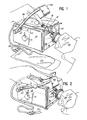
- the apparatus shown comprises a casing 10 which defines a recess 12, which is proportioned to receive a joined set of sterile connectors 14, 16, each of which includes a pair of abutting, facing thermoplastic diaphragms 18 through which an aperture is to be punched by means of radiation in the manner specifically described by the patents and applications first cited above. It is contemplated that any design of sterile connector may be utilized, although the apparatus of this invention is preferably proportioned with a recess 12 shaped to snugly receive the contours of the specific design of sterile connector to be processed.
- housing 10 carries a filament-type light bulb 20 for use as the radiant beam source herein, supplied with operating electric current as controlled by circuitry 21, of a design as shown in Figure 5.
- filament-type light bulb 20 preferably comprises a small, hot filament 22, having an elliptical, preferably aluminized reflector 24 capable of reflecting substantial radiation emitted by the filament and focusing it at a predetermined position 26, which is occupied by a preferably central portion of the abutting, facing diaphragms 18.
- the focused spot of radiation from light bulb 20 on diaphragm 18 is preferably substantially no more than 0.3 inch (0.76cm) in diameter, and typically 0.2 inch (0.51cm) in diameter.
- a type of lamp used herein may be a type EKN lamp rated at 120 watts at 17.5 volts and a 3200° color temperature having a 0.141 inch (0.36cm) diameter focus circle at 1.5 inches (3.8cm) in front of the reflector's rim which would be the desired point where the membranes would be positioned.
- the lamp can have an aluminized reflector, and would be a small-envelope tungsten filament halogen cycle quartz bulb with its filament located in manufacture at the desired first focus of the ellipse of the reflector. It may be desired to operate the lamp at less than its rated wattage, for example 55 watts, to obtain the desired amount of radiation for optimum opening of the apertures through the diaphragms.
- the specific sterile connector system may be part of a system of containers 26, 30 which are initially separate, and communicate through tubings 32, 34 to their respective sterile connectors 14, 16, which are attached in sealed manner to the tubings.
- the separate containers may be locked together by means of their sterile connectors, inserted into recess 12, and processed by the apparatus of this invention for reliable hole opening procedure, so that a sterile access may be obtained between the two containers.
- one of the containers 30 may contain a carbohydrate solution, and the other container 28 may contain an amino acid or a protein hydrolysate solution, with the two containers being intended for mixing together to provide a total parenteral nutrient solution for a hospitalized patient which may be stored for a period of time after mixing because of the sterile procedure used.
- the containers may be for the transfer of blood or its components.
- each sterile connector 14, 16 terminates in a hollow spike 36-which is positioned within a boot 38 which may be collapsed so that each spike 36 can penetrate a diaphragm 40, to provide an auxiliary openable seal in a manner described in some of the patent applications cited above.
- the first seat 42 is defined, being preferably of the shape of sterile connector unit 14 intended to rest against it. Within first seat 42 an aperture 44 is provided for the light from lamp 20 to pass to diaphragms 18.
- Pivotable switch arm 46 is provided with head 48, being manually operable and preferably equipped with conventional spring means 41 to cause it to retract to position shown in Figure 1, being pivotably depressable by hand to bring the second seat 49 of head 48 into engagement with the sterile connector positioned on first seat 42.
- Second seat 49 also preferably has a contour to match the shape of the sterile connector it rests against.
- Head 48 of switch arm 46 defines tunnel 50 pass- through second seat 49, at the bottom of which resides photocell 52 described above.
- Photocell 52 is electrically connected by lead 54 to circuitry as described below for shutting off lamp 20 upon the sensing of light from lamp 20. As shown, photocell 52 is positioned in the shadow defined by diaphragms 16, 18 relative to lamp 20, so that a hole must be formed in the diaphragms before light from lamp 20 falls on photocell 52. Photocell 52 is positioned at the bottom of tunnel 50 so that it is shielded from stray light, for example light which is conveyed through a transparent housing, when used, of the sterile connectors 14, 16.
- switch arm 46 rotates shaft 47 and spring- biased inner arm 53 on shaft 47, to actuate switch 51 to turn the system on in the position shown in Figure 2, and to spring arm 46 out of the closed position when released.
- This causes switch to illuminate lamp 20, as one manually holds switch arm 46 in its active position, or alternatively, as can be retained there by a latch or the like as desired.
- the hole opening operation is completed, so that a beam passes through diaphragms 16, 18 to impinge upon photocell 52.
- the consequent electrical impulse passes through lead 54 into the circuitry to be specifically discussed below to ultimately deactivate lamp 20 in a manner which may be modified by the timer means of the circuitry.
- the device of this invention thus provides the opportunity for rapid opening of sterile connections in systems such as containers 28, 30 using unskilled personnel, since the timing of the radiation exposure can be completely controlled by the apparatus of this invention.
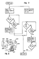
- safety timer 77 When switch 51 is closed, line 60 activates safety timer 77; line 62 activates an on-off memory circuit 64; and line 130 activates the no-hole safety timer 86.
- safety timer 77 has a timing cycle of 3.3 seconds and no-hole shut off safety timer has a timing cycle of 17.5 seconds.
- the output of memory circuit 64 is amplified by amplifier 66 and fed via line 68 to an optically activated SCR switch 70.
- This optically activated SCR switch 70 when energized, allows current to flow via AC line 72 through the filament of lamp 20.
- a capacitive reactance circuit 74 is in series with the AC line to limit the current to the filament, and to allow long lamp life by slow turn on of the filament.
- no-hole shut off safety timer 86 is coupled via line 88 to the off input of on-off memory circuit 64.
- a signal will be fed via line 120 to enable direct shut-off gate 80.
- a signal to direct shut-off gate 80 from line 106 will operate to provide a signal via line 84 to the off input of on-off memory circuit 64. Once the off input of on-off memory 64 is pulsed, the lamp 20 will be effectively shut off.
- Photocell 52 is positioned on the opposite side of diaphragm 18 from lamp 20. Once photocell 52 receives light, direct shut-off gate 80 will receive a signal via line 106. Prior to the completion of the 3.3 second time cycle of safety timer 77, direct shut-off gate 80 is not inhibited and thus the signal on line 106 will pass through gate 80 to line 84 and to the off input of on-off memory memory 64, thereby effectively shutting off lamp 20. However, once the timing cycle of safety timer 77-is completed, the signal on line 120 will operate to inhibit direct shut off gate 80 and therafter when light is sensed the signal on line 54 cannot go through gate 80 and can only go through hole enlargement timer 90.
- hole enlargement timer 90 has a timing cycle of 0.5 second. Until the 0.5 second timing cycle of hole enlargement timer 90 is completed, lamp 20 will continue to be energized to form the proper size hole. However, once the timing cycle of hole enlargement timer 90 is completed, a signal via line 92 will pulse the off input of on-off memory 64 to effectively shut off lamp 20.
- the diaphragm 18 is in line 76 normally blocking the light from lamp 20 to photocell 52 which is in the form of phototransistor.
- the emitter of phototransistor 52 is connected through an inverter 100 to hole enlargement timer 90, which comprises a resistor 102 in series with a Schmidt trigger 103, and having capacitor 104 in shunt with the line coupling resistor 102 to Schmidt trigger 103.
- the output 92 of Schmidt trigger 103 is coupled to an input of NOR gate 81.
- the output of inverter 100 is also coupled via line 106 to an input of NOR gate 80, the output 78 of which is connected to another input of NOR gate 81.
- Switch 51 is coupled to energize line 60 which is coupled through inverter 110 to safety timer 77.
- Safety timer 77 comprises a parallel connected diode 112 and capacitor 114 which is coupled to Schmidt trigger 116, with a shunt resistor 118 connected to the line between capacitor 114 and Schmidt trigger 116.
- the output of Schmidt trigger 116 is fed via line 120 to the other input of NOR gate 80.
- NOR gate 81 The output of NOR gate 81 is connected through inverter 122 to the off input of an RS flip-flop 64.
- Line 120 is connected to inverter 163.
- Line 62 is connected through a series capacitor 124 and shunt resistor 126 to the on input of RS flip-flop 64.
- flip-flop 64 The output of flip-flop 64 is connected via line 130 and line 132 to no-hole shut off safety timer 86.
- Timer 86 comprises an oscillator 134 including a Schmidt trigger 136 and resistor 138 coupled to a two-decade up counter 140.
- the output of up counter 140 is fed via line 88 to another input of NOR gate 81.
- SCR switch 70 comprises a resistor 146 in series with LED 148 of an optical coupler which includes the LED 148 having its light impinging upon an SCR (not shown) which is in a bridge circuit allowing it to fire simultaneously two back-to-back SCR's 150, 151.
- the optical coupler provides isolation between the logic circuitry and the main line voltage to lamp 20.
- the LED 148 and its connected circuitry is low voltage DC while the back-to-back SCR's 150, 151 switch the main AC line voltage through lamp 20.
- Capacitive reactance circuit 74 comprises two back-to-back polarized high voltage electrolytic capacitors 154, 155, each of which is shunted by a diode connected in the following manner.
- Diode 156 which shunts capacitor 154 has its anode connected to the negative side of the capacitor and its cathode connected to the positive side of the capacitor 154.
- Diode 158 which is coupled in shunt with capacitor 155, has its anode connected to the negative side of capacitor 155 and its cathode connected to the positive side of capacitor 155.
- the positive side of capacitor 155 is also connected via line 160 to one side of the filament of lamp 20 with the other side of the filament being connected to an appropriate alternating current source 162.
- safety timer 77 has a timing cycle of 3.3 seconds.
- hole enlargement timer 90 will become activated. As stated previously, hole enlargement timer 90 is operative to set the hole size by maintaining the light burning for a predetermined amount of time once the hole is sensed. After the set interval of hole enlargement timer 90 is completed (for example after 0.5 second) a signal at input NOR gate 81 will operate to pulse the off input of flip-flop 64, thereby erfectively shutting off the lamp 20.
- flip-flop 64 actuates the two-decade up counter 140 of no-hole shut off safety timer 86. After a predetermined time interval (for example 17.5 seconds) if light has not been sensed by phototransistor 52, a signal via line 88 to an input of NOR gate 81 will pulse the off input of flip-flop 64 to effectively shut off lamp 20.
- a predetermined time interval for example 17.5 seconds
- the AC circuit which includes the back-to-back SCR's 150, 151 and the capacitive reactance circuit 74, provides a transformerless drive for the low voltage lamp 20.
- lamp 20 may be coupled to a 120 or a 220 volt AC source without utilizing a transformer notwithstanding the fact that the low voltage lamp 20 may utilize only 17 volts.
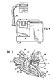
- a modified apparatus in accordance with this invention is shown.
- a pair of sterile connectors 200 are shown having abutting opaque, thermoplastic diaphragms 202 through which an aperture is desired to be melted.
- the outer portions of the sterile connectors are at least partly transparent to permit the application of radiation to the opaque diaphragms.
- focused lamp 204 is provided to irradiate and melt a hole through diaphragms 202.
- an additional one or more focused lamps 206 may be provided for added irradiation of the other side of the membrane, if such is desired.
- Electric circuit means 208 is schematically shown, with electrical lines 209 connecting lamps 204, 206, with the circuit.
- a photocell 210 specifically a phototransdu- cer, is positioned in a housing 212 having an aperture 214 to receive reflected light.
- a light pipe 216 which may be made of glass or plastic, preferably shielded with an opaque shielding, constitutes a part of the photocell means having a tip 218 positioned where a properly positioned diaphragm 202 initially shades the photocell means from the beam emitted by lamp 204.
- the beam passes through diaphragm 202 and is taken up by the end of light pipe 216 to be transferred to the photocell.
- Circuitry 208 may be similar to that previously described to deactivate lamps 204, 206 when photocell 210 senses the light beam.
- the lamp 206 if present, does not influence the operation of the system since its radiation cannot be transferred into light pipe 216.
- the actual photocell 210 may be positioned away from the lamp system, where it is not subject to heating from the irradiation and thus can operate without varying its properties due to such heating.
- the light can be attenuated as desired through light pipe 216, so that photocells which do not function well in the presence of a direct beam from lamp 204 can be utilized in the more attenuated light coming through the light pipe 216.
Landscapes
- Engineering & Computer Science (AREA)
- Mechanical Engineering (AREA)
- Health & Medical Sciences (AREA)
- Physics & Mathematics (AREA)
- Electromagnetism (AREA)
- Toxicology (AREA)
- Life Sciences & Earth Sciences (AREA)
- Pharmacology & Pharmacy (AREA)
- Optics & Photonics (AREA)
- Animal Behavior & Ethology (AREA)
- General Health & Medical Sciences (AREA)
- Public Health (AREA)
- Veterinary Medicine (AREA)
- External Artificial Organs (AREA)
- Medical Preparation Storing Or Oral Administration Devices (AREA)
- Apparatus For Disinfection Or Sterilisation (AREA)
Applications Claiming Priority (2)
| Application Number | Priority Date | Filing Date | Title |
|---|---|---|---|
| US230076 | 1981-01-30 | ||
| US06/230,076 US4356394A (en) | 1981-01-30 | 1981-01-30 | Apparatus for applying radiant beam |
Publications (3)
| Publication Number | Publication Date |
|---|---|
| EP0057545A2 true EP0057545A2 (de) | 1982-08-11 |
| EP0057545A3 EP0057545A3 (en) | 1982-08-25 |
| EP0057545B1 EP0057545B1 (de) | 1986-04-23 |
Family
ID=22863861
Family Applications (1)
| Application Number | Title | Priority Date | Filing Date |
|---|---|---|---|
| EP19820300347 Expired EP0057545B1 (de) | 1981-01-30 | 1982-01-25 | Vorrichtung zur Anwendung von Strahlungsenergie |
Country Status (5)
| Country | Link |
|---|---|
| US (1) | US4356394A (de) |
| EP (1) | EP0057545B1 (de) |
| JP (1) | JPS57148952A (de) |
| CA (1) | CA1183577A (de) |
| DE (1) | DE3270702D1 (de) |
Cited By (1)
| Publication number | Priority date | Publication date | Assignee | Title |
|---|---|---|---|---|
| EP0193867A3 (de) * | 1985-03-01 | 1987-08-05 | Abbott Laboratories | Ansteuerschaltung für eine Wärmewelle zur Analyse biologischer Stoffe |
Families Citing this family (10)
| Publication number | Priority date | Publication date | Assignee | Title |
|---|---|---|---|---|
| EP0128904A1 (de) * | 1982-12-16 | 1984-12-27 | Baxter Travenol Laboratories, Inc. | Fluidübertragungsglied und zusammenbau der eine strahlungsenergie absorbierende wand mit optimalen schmelzmerkmalen einschliesst |
| US4807676A (en) * | 1985-02-26 | 1989-02-28 | Baxter International Inc. | Fluid transfer workstation |
| DE3683925D1 (de) * | 1985-02-26 | 1992-03-26 | Baxter Int | Transfersystem fuer fluide. |
| SE459126B (sv) * | 1987-09-15 | 1989-06-05 | Gambro Engstrom Ab | Optisk gasanalysator |
| US20070060302A1 (en) * | 2005-08-17 | 2007-03-15 | Igt | Scan based configuration control in a gaming environment |
| WO2008131442A2 (en) * | 2007-04-24 | 2008-10-30 | Hyclone Laboratories, Inc. | Sterile connector systems |
| US7938454B2 (en) * | 2007-04-24 | 2011-05-10 | Hyclone Laboratories, Inc. | Sterile connector systems |
| US8448992B2 (en) * | 2011-02-16 | 2013-05-28 | Fenwal, Inc. | Sterile docking device, medical fluid flow system with sterile docking device and method of using same |
| US9839582B2 (en) | 2014-12-02 | 2017-12-12 | Fenwal, Inc. | Sterile connection syringe assemblies |
| US10525249B2 (en) * | 2016-03-07 | 2020-01-07 | Fenwal, Inc. | System and method for creating sterile connections using ultraviolet light |
Family Cites Families (4)
| Publication number | Priority date | Publication date | Assignee | Title |
|---|---|---|---|---|
| US3509317A (en) * | 1967-08-01 | 1970-04-28 | North American Rockwell | Indirect radiant heat soldering apparatus |
| US4157723A (en) * | 1977-10-19 | 1979-06-12 | Baxter Travenol Laboratories, Inc. | Method of forming a connection between two sealed conduits using radiant energy |
| US4265280A (en) * | 1979-01-23 | 1981-05-05 | Baxter Travenol Laboratories, Inc. | Connector member for sealed conduits |
| US4325417A (en) * | 1979-04-06 | 1982-04-20 | Baxter Travenol Laboratories, Inc. | Connector member for sealed conduits utilizing crystalline plastic barrier membrane |
-
1981
- 1981-01-30 US US06/230,076 patent/US4356394A/en not_active Expired - Fee Related
-
1982
- 1982-01-08 CA CA000393838A patent/CA1183577A/en not_active Expired
- 1982-01-25 DE DE8282300347T patent/DE3270702D1/de not_active Expired
- 1982-01-25 EP EP19820300347 patent/EP0057545B1/de not_active Expired
- 1982-01-25 JP JP1082382A patent/JPS57148952A/ja active Pending
Cited By (1)
| Publication number | Priority date | Publication date | Assignee | Title |
|---|---|---|---|---|
| EP0193867A3 (de) * | 1985-03-01 | 1987-08-05 | Abbott Laboratories | Ansteuerschaltung für eine Wärmewelle zur Analyse biologischer Stoffe |
Also Published As
| Publication number | Publication date |
|---|---|
| JPS57148952A (en) | 1982-09-14 |
| US4356394A (en) | 1982-10-26 |
| DE3270702D1 (en) | 1986-05-28 |
| EP0057545A3 (en) | 1982-08-25 |
| EP0057545B1 (de) | 1986-04-23 |
| CA1183577A (en) | 1985-03-05 |
Similar Documents
| Publication | Publication Date | Title |
|---|---|---|
| EP0057545B1 (de) | Vorrichtung zur Anwendung von Strahlungsenergie | |
| EP0080494B1 (de) | Ultraviolette bestrahlung eines dialysegeräts | |
| US11439188B2 (en) | Automatically controlled heat-not-burn electronic cigarette device and control method thereof | |
| US4340097A (en) | Connector member for sealed conduits | |
| US6461568B1 (en) | Method and apparatus for sterilizing small objects | |
| US7459054B2 (en) | Apparatus and method for connecting and disconnecting flexible tubing | |
| JP4437281B2 (ja) | 流体処理セットおよび流体処理セットのための整理収納装置 | |
| JP2003501175A (ja) | 生物学的流体を加工および処理するための加工セットおよび方法 | |
| JP2000511497A (ja) | パッケージ及びその内容物のパルス光滅菌におけるパラメータ制御 | |
| EP0215057A1 (de) | Arbeitsstation zur übertragung von flüssigkeiten | |
| JP2003501148A (ja) | 生物学的流体を光で加工および処理するための装置、システムおよび方法 | |
| JPH02504004A (ja) | 管接続物を交換及び照射するための装置 | |
| KR101906230B1 (ko) | 젖병 소독기 | |
| KR101898133B1 (ko) | 젖병 소독기 | |
| JPS58221942A (ja) | 歯科材料処理装置 | |
| CN107693885B (zh) | 用于输液的智能放液器及包括该智能放液器的输液装置 | |
| JP2000085726A (ja) | 容器の殺菌方法及び装置 | |
| JPH04117962A (ja) | コネクタ滅菌装置 | |
| JPS63252248A (ja) | 細胞分析装置 | |
| JPH02302256A (ja) | コンタクトレンズ用消毒器 | |
| HUT54899A (en) | Device for sterilizing cutting and chopping devices particularly meat-industrial ones | |
| JPH0520719U (ja) | 歯科用自動コツプ給水装置 |
Legal Events
| Date | Code | Title | Description |
|---|---|---|---|
| PUAI | Public reference made under article 153(3) epc to a published international application that has entered the european phase |
Free format text: ORIGINAL CODE: 0009012 |
|
| PUAL | Search report despatched |
Free format text: ORIGINAL CODE: 0009013 |
|
| AK | Designated contracting states |
Designated state(s): BE DE FR GB |
|
| AK | Designated contracting states |
Designated state(s): BE DE FR GB |
|
| 17P | Request for examination filed |
Effective date: 19821116 |
|
| GRAA | (expected) grant |
Free format text: ORIGINAL CODE: 0009210 |
|
| AK | Designated contracting states |
Kind code of ref document: B1 Designated state(s): BE DE FR GB |
|
| REF | Corresponds to: |
Ref document number: 3270702 Country of ref document: DE Date of ref document: 19860528 |
|
| ET | Fr: translation filed | ||
| PLBE | No opposition filed within time limit |
Free format text: ORIGINAL CODE: 0009261 |
|
| STAA | Information on the status of an ep patent application or granted ep patent |
Free format text: STATUS: NO OPPOSITION FILED WITHIN TIME LIMIT |
|
| 26N | No opposition filed | ||
| PGFP | Annual fee paid to national office [announced via postgrant information from national office to epo] |
Ref country code: FR Payment date: 19890117 Year of fee payment: 8 |
|
| PGFP | Annual fee paid to national office [announced via postgrant information from national office to epo] |
Ref country code: GB Payment date: 19890125 Year of fee payment: 8 |
|
| PGFP | Annual fee paid to national office [announced via postgrant information from national office to epo] |
Ref country code: DE Payment date: 19890130 Year of fee payment: 8 |
|
| PGFP | Annual fee paid to national office [announced via postgrant information from national office to epo] |
Ref country code: BE Payment date: 19890421 Year of fee payment: 8 |
|
| REG | Reference to a national code |
Ref country code: FR Ref legal event code: CD |
|
| PG25 | Lapsed in a contracting state [announced via postgrant information from national office to epo] |
Ref country code: GB Effective date: 19900125 |
|
| PG25 | Lapsed in a contracting state [announced via postgrant information from national office to epo] |
Ref country code: BE Effective date: 19900131 |
|
| BERE | Be: lapsed |
Owner name: BAXTER INTERNATIONAL INC. Effective date: 19900131 |
|
| GBPC | Gb: european patent ceased through non-payment of renewal fee | ||
| PG25 | Lapsed in a contracting state [announced via postgrant information from national office to epo] |
Ref country code: FR Effective date: 19900928 |
|
| PG25 | Lapsed in a contracting state [announced via postgrant information from national office to epo] |
Ref country code: DE Effective date: 19901002 |
|
| REG | Reference to a national code |
Ref country code: FR Ref legal event code: ST |