EP0057052B1 - Brücken grosser Spannweite - Google Patents
Brücken grosser Spannweite Download PDFInfo
- Publication number
- EP0057052B1 EP0057052B1 EP82300078A EP82300078A EP0057052B1 EP 0057052 B1 EP0057052 B1 EP 0057052B1 EP 82300078 A EP82300078 A EP 82300078A EP 82300078 A EP82300078 A EP 82300078A EP 0057052 B1 EP0057052 B1 EP 0057052B1
- Authority
- EP
- European Patent Office
- Prior art keywords
- deck
- bridge
- decks
- spans
- supported
- Prior art date
- Legal status (The legal status is an assumption and is not a legal conclusion. Google has not performed a legal analysis and makes no representation as to the accuracy of the status listed.)
- Expired
Links
- 239000000725 suspension Substances 0.000 claims description 12
- 238000005452 bending Methods 0.000 description 3
- 238000010276 construction Methods 0.000 description 3
- 230000010355 oscillation Effects 0.000 description 2
- 229910000831 Steel Inorganic materials 0.000 description 1
- 238000013016 damping Methods 0.000 description 1
- 230000000694 effects Effects 0.000 description 1
- 238000000926 separation method Methods 0.000 description 1
- 239000010959 steel Substances 0.000 description 1
Images

Classifications
-
- E—FIXED CONSTRUCTIONS
- E01—CONSTRUCTION OF ROADS, RAILWAYS, OR BRIDGES
- E01D—CONSTRUCTION OF BRIDGES, ELEVATED ROADWAYS OR VIADUCTS; ASSEMBLY OF BRIDGES
- E01D11/00—Suspension or cable-stayed bridges
- E01D11/02—Suspension bridges
Definitions
- the present invention relates to long-span bridges and is concerned with the problem of aerodynamically-induced instability of the deck of such a bridge in high winds.
- a long-span bridge in which the deck is supported with some freedom to twist about its longitudinal axis characterized in that the bridge is composed of two or more parallel spans having independently-supported decks, each pair of spans being transversely spaced by a distance greater than the width of either deck and joined at intervals along their length by stiff transverse beams which couple the two decks to behave in torsion as a single substantially rigid body.
- the bridge will be designed with two parallel spans but the invention provides for increasing the traffic capacity by building an additional span or spans parallel to the first two and interconnecting the additional span or spans with the existing structure.
- the transverse beams are connected at their ends to the decks and they preferably extend under the two decks.
- the transverse beams could be arranged to connect all four cables.
- the decks are directly supported from their own suspension cables or other supports and the transverse beams therefore normally carry no load except their own weight.
- the necessary stiffness in the beams can be achieved with a structure whose weight is only a few per cent of the total weight of the bridge superstructure.
- the separation of the two decks which is preferably by a gap of three or more deck widths, results in very high aerodynamic damping of both torsional and bending modes of oscillation.
- the wind speed at which divergence will occur increases with the spacing between the decks and can thus be made as high as required.
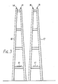
- the bridge comprises two decks or carriageways 10 and 11 which run parallel to one another and are of the same structure and dimensions.
- the deck 10 is carried by vertical hangers 12 and 13 attached to respective suspension cables 14 and 15.
- the cables 14 and 15, which are spaced by the width of the deck 10, pass over towers at the ends of the span and are anchored in conventional manner.
- One of the end towers 16 is seen in Fig. 3 and the end of the deck 10 is attached to the tower 16.
- the structure described so far consists of two independent suspension bridges of conventional design built side by side.
- the two decks 10 and 11 are independently supported from their own pairs of transversely-spaced suspension cables.
- the two parallel decks are separated by a gap whose width is not less than the width of either of the decks and is preferably three or more times that width. Bridging this gap are a series of transverse girders 22 at intervals along the length of the bridge and diagonal shear braces 23.
- the stiffness of the girders 22 and the manner in which they are attached to the decks is such that the two decks 10 and 11 act substantially as a single rigid body in regard to rotation in a transverse plane such as that of Fig. 2.
- the girders 22 in the present construction extend under the decks 10 and 11 and are attached to their lower sides.
- each deck has a pair of suspension cables it is also possible to suspend each deck from its own single suspension cable, for example by using inclined hangers connecting the edges of the deck to the cable.
- the invention is equally effective in such a construction.
- the invention is also applicable in cable-stayed structures and in structures where each deck is supported on one or more cables which are suspended in an arc below the deck.
Landscapes
- Engineering & Computer Science (AREA)
- Architecture (AREA)
- Civil Engineering (AREA)
- Structural Engineering (AREA)
- Bridges Or Land Bridges (AREA)
Claims (6)
Applications Claiming Priority (2)
| Application Number | Priority Date | Filing Date | Title |
|---|---|---|---|
| GB8100448 | 1981-01-08 | ||
| GB8100448 | 1981-01-08 |
Publications (2)
| Publication Number | Publication Date |
|---|---|
| EP0057052A1 EP0057052A1 (de) | 1982-08-04 |
| EP0057052B1 true EP0057052B1 (de) | 1985-04-17 |
Family
ID=10518856
Family Applications (1)
| Application Number | Title | Priority Date | Filing Date |
|---|---|---|---|
| EP82300078A Expired EP0057052B1 (de) | 1981-01-08 | 1982-01-07 | Brücken grosser Spannweite |
Country Status (8)
| Country | Link |
|---|---|
| US (1) | US4451950A (de) |
| EP (1) | EP0057052B1 (de) |
| JP (1) | JPS57137503A (de) |
| CA (1) | CA1169208A (de) |
| DE (1) | DE3263050D1 (de) |
| DK (1) | DK5182A (de) |
| IT (1) | IT8168714A0 (de) |
| TR (1) | TR21516A (de) |
Families Citing this family (8)
| Publication number | Priority date | Publication date | Assignee | Title |
|---|---|---|---|---|
| FR2626909A1 (fr) * | 1988-02-05 | 1989-08-11 | Muller Jean | Pont haubane et son procede de construction |
| DK169444B1 (da) * | 1992-02-18 | 1994-10-31 | Cowi Radgivende Ingeniorer As | System og fremgangsmåde til modvirkning af vindinducerede svingninger i en brodrager |
| IT1255926B (it) * | 1992-10-28 | 1995-11-17 | Stretto Di Messina Spa | Struttura di impalcato per ponte sospeso |
| JPH06341110A (ja) * | 1993-06-02 | 1994-12-13 | Hiroyuki Mizukami | 骨格構造形式の橋及びその架設工法 |
| JPH09111716A (ja) * | 1995-10-16 | 1997-04-28 | Kawada Kogyo Kk | 暴風時質量偏載吊橋 |
| RU2150548C1 (ru) * | 1998-12-21 | 2000-06-10 | Самсонов Сергей Николаевич | Устройство усиления трубопроводного перехода |
| RU2166576C1 (ru) * | 2000-04-17 | 2001-05-10 | Лунев Лев Алексеевич | Устройство усиления надземного трубопроводного перехода с помощью рычажной установки |
| US7415746B2 (en) * | 2005-12-01 | 2008-08-26 | Sc Solutions | Method for constructing a self anchored suspension bridge |
Family Cites Families (12)
| Publication number | Priority date | Publication date | Assignee | Title |
|---|---|---|---|---|
| US629935A (en) * | 1898-07-11 | 1899-08-01 | Nelson H Sturgis | Suspension-bridge. |
| US1895734A (en) * | 1927-04-27 | 1933-01-31 | Allan C Rush | Triadic, interlocking strut and truss, catenary, and suspension bridge |
| US2333391A (en) * | 1941-02-06 | 1943-11-02 | Holton D Robinson | Aerodynamically stable suspension bridge |
| US2642598A (en) * | 1946-12-09 | 1953-06-23 | John W Beretta | Rigid tension-truss bridge |
| DE1098024B (de) * | 1957-05-28 | 1961-01-26 | Johannes Doernen | Tragwerk ueber zwei oder mehr Felder |
| DE1223866B (de) * | 1960-05-16 | 1966-09-01 | Gilbert Roberts | Haengebruecke |
| US3211110A (en) * | 1962-07-05 | 1965-10-12 | Robert M Pierson | Roadway structures |
| CH467387A (de) * | 1965-10-11 | 1969-01-15 | Matthews Pierson Robert | Hängende Fahrbahnkonstruktion |
| US3406616A (en) * | 1966-04-14 | 1968-10-22 | Mclean Edwin Lee | Bridge and traffic system |
| GB1120496A (en) * | 1966-05-17 | 1968-07-17 | William Wilkins Pleasants | Improvements in overpasses |
| FR1539155A (fr) * | 1967-08-02 | 1968-09-13 | Pont haubané à superstructure triangulaire | |
| DE2919318A1 (de) * | 1977-05-25 | 1980-12-04 | Rudolf Baltensperger | Schienenhaengebahn-anlage |
-
1981
- 1981-12-24 CA CA000393241A patent/CA1169208A/en not_active Expired
- 1981-12-29 US US06/335,127 patent/US4451950A/en not_active Expired - Fee Related
- 1981-12-30 IT IT8168714A patent/IT8168714A0/it unknown
-
1982
- 1982-01-06 TR TR21516A patent/TR21516A/xx unknown
- 1982-01-07 JP JP57000647A patent/JPS57137503A/ja active Pending
- 1982-01-07 EP EP82300078A patent/EP0057052B1/de not_active Expired
- 1982-01-07 DE DE8282300078T patent/DE3263050D1/de not_active Expired
- 1982-01-08 DK DK5182A patent/DK5182A/da not_active Application Discontinuation
Also Published As
| Publication number | Publication date |
|---|---|
| US4451950A (en) | 1984-06-05 |
| EP0057052A1 (de) | 1982-08-04 |
| IT8168714A0 (it) | 1981-12-30 |
| CA1169208A (en) | 1984-06-19 |
| JPS57137503A (en) | 1982-08-25 |
| DE3263050D1 (en) | 1985-05-23 |
| DK5182A (da) | 1982-07-09 |
| TR21516A (tr) | 1984-08-08 |
Similar Documents
| Publication | Publication Date | Title |
|---|---|---|
| US7743444B2 (en) | Cable stayed suspension bridge making combined use of one-box and two-box girders | |
| US4993094A (en) | Bridge comprising a bridge floor and elements supporting said floor, particularly a long span cable-stayed bridge, and process of construction | |
| US5060332A (en) | Cable stayed bridge construction | |
| US4513465A (en) | Stiffening girder for a stayed cable bridge | |
| US4987629A (en) | Deck for wide-span bridge | |
| EP0057052B1 (de) | Brücken grosser Spannweite | |
| CA1223108A (en) | Stiffening girder type suspension bridge | |
| EP0195861A1 (de) | Hängebrücke | |
| CN112144371A (zh) | 一种斜拉悬索协作体系桥 | |
| US4866803A (en) | Bridge structure with inclined towers | |
| UA50770C2 (uk) | Міст та спосіб його стабілізації | |
| US5121518A (en) | Cable-stayed bridge and construction process | |
| US3132363A (en) | Suspension bridges | |
| CA2147978C (en) | Suspension bridge framework | |
| EP0666942B1 (de) | Windbrecher für eine hängebrücke mit schwingungsdämpfer | |
| US2642598A (en) | Rigid tension-truss bridge | |
| US3688327A (en) | Cellular building structure | |
| US5070566A (en) | Hybrid bridge structure | |
| CN211522817U (zh) | 一种联塔分幅四线铁路斜拉桥 | |
| CA1190710A (en) | Suspension bridge | |
| Gilsanz et al. | Cable-Stayed Bridges: Degrees of Anchorng | |
| SU1622491A1 (ru) | Пролетное строение однопутного железнодорожного моста с ездой понизу | |
| US2402124A (en) | Bridge construction | |
| SU1161622A1 (ru) | Сейсмостойкий мост | |
| RU2057835C1 (ru) | Висячий мост |
Legal Events
| Date | Code | Title | Description |
|---|---|---|---|
| PUAI | Public reference made under article 153(3) epc to a published international application that has entered the european phase |
Free format text: ORIGINAL CODE: 0009012 |
|
| AK | Designated contracting states |
Designated state(s): DE FR GB IT SE |
|
| 17P | Request for examination filed |
Effective date: 19830125 |
|
| ITF | It: translation for a ep patent filed | ||
| RAP1 | Party data changed (applicant data changed or rights of an application transferred) |
Owner name: NMI LIMITED |
|
| RIN1 | Information on inventor provided before grant (corrected) |
Inventor name: RICHARDSON, JOHN ROY |
|
| GRAA | (expected) grant |
Free format text: ORIGINAL CODE: 0009210 |
|
| AK | Designated contracting states |
Designated state(s): DE FR GB IT SE |
|
| PG25 | Lapsed in a contracting state [announced via postgrant information from national office to epo] |
Ref country code: SE Effective date: 19850430 |
|
| REF | Corresponds to: |
Ref document number: 3263050 Country of ref document: DE Date of ref document: 19850523 |
|
| ET | Fr: translation filed | ||
| PLBI | Opposition filed |
Free format text: ORIGINAL CODE: 0009260 |
|
| 26 | Opposition filed |
Opponent name: FRIED. KRUPP GMBH Effective date: 19860113 |
|
| RDAG | Patent revoked |
Free format text: ORIGINAL CODE: 0009271 |
|
| STAA | Information on the status of an ep patent application or granted ep patent |
Free format text: STATUS: PATENT REVOKED |
|
| 27W | Patent revoked |
Effective date: 19861208 |
|
| GBPR | Gb: patent revoked under art. 102 of the ep convention designating the uk as contracting state | ||
| REG | Reference to a national code |
Ref country code: FR Ref legal event code: ST |