EP0057044A2 - Cleaning machine - Google Patents
Cleaning machine Download PDFInfo
- Publication number
- EP0057044A2 EP0057044A2 EP82200109A EP82200109A EP0057044A2 EP 0057044 A2 EP0057044 A2 EP 0057044A2 EP 82200109 A EP82200109 A EP 82200109A EP 82200109 A EP82200109 A EP 82200109A EP 0057044 A2 EP0057044 A2 EP 0057044A2
- Authority
- EP
- European Patent Office
- Prior art keywords
- granules
- liquid
- goods
- cleaning machine
- cassette
- Prior art date
- Legal status (The legal status is an assumption and is not a legal conclusion. Google has not performed a legal analysis and makes no representation as to the accuracy of the status listed.)
- Withdrawn
Links
- 238000004140 cleaning Methods 0.000 title claims abstract description 19
- 239000008187 granular material Substances 0.000 claims abstract description 58
- 239000007788 liquid Substances 0.000 claims abstract description 54
- 238000005422 blasting Methods 0.000 claims abstract description 6
- 230000005484 gravity Effects 0.000 claims description 5
- 239000000463 material Substances 0.000 claims description 2
- 239000004033 plastic Substances 0.000 claims description 2
- 229920003023 plastic Polymers 0.000 claims description 2
- 238000004851 dishwashing Methods 0.000 description 21
- 239000010794 food waste Substances 0.000 description 5
- 229920004943 Delrin® Polymers 0.000 description 3
- 230000000694 effects Effects 0.000 description 3
- 238000006073 displacement reaction Methods 0.000 description 2
- 238000011010 flushing procedure Methods 0.000 description 2
- 238000005192 partition Methods 0.000 description 2
- 238000005406 washing Methods 0.000 description 2
- 239000004677 Nylon Substances 0.000 description 1
- 238000009825 accumulation Methods 0.000 description 1
- 238000010276 construction Methods 0.000 description 1
- 239000000356 contaminant Substances 0.000 description 1
- 230000008878 coupling Effects 0.000 description 1
- 238000010168 coupling process Methods 0.000 description 1
- 238000005859 coupling reaction Methods 0.000 description 1
- 239000003599 detergent Substances 0.000 description 1
- 230000001627 detrimental effect Effects 0.000 description 1
- 238000001035 drying Methods 0.000 description 1
- 230000037431 insertion Effects 0.000 description 1
- 238000003780 insertion Methods 0.000 description 1
- 229920001778 nylon Polymers 0.000 description 1
- 102000004169 proteins and genes Human genes 0.000 description 1
- 108090000623 proteins and genes Proteins 0.000 description 1
- 238000005507 spraying Methods 0.000 description 1
- 238000004659 sterilization and disinfection Methods 0.000 description 1
- XLYOFNOQVPJJNP-UHFFFAOYSA-N water Substances O XLYOFNOQVPJJNP-UHFFFAOYSA-N 0.000 description 1
Images


Classifications
-
- A—HUMAN NECESSITIES
- A47—FURNITURE; DOMESTIC ARTICLES OR APPLIANCES; COFFEE MILLS; SPICE MILLS; SUCTION CLEANERS IN GENERAL
- A47L—DOMESTIC WASHING OR CLEANING; SUCTION CLEANERS IN GENERAL
- A47L15/00—Washing or rinsing machines for crockery or tableware
- A47L15/0094—Washing or rinsing machines for crockery or tableware cleaning with abrasive solid particles, e.g. by blasting the crockery with liquid containing granules
-
- A—HUMAN NECESSITIES
- A47—FURNITURE; DOMESTIC ARTICLES OR APPLIANCES; COFFEE MILLS; SPICE MILLS; SUCTION CLEANERS IN GENERAL
- A47L—DOMESTIC WASHING OR CLEANING; SUCTION CLEANERS IN GENERAL
- A47L15/00—Washing or rinsing machines for crockery or tableware
- A47L15/0002—Washing processes, i.e. machine working principles characterised by phases or operational steps
-
- A—HUMAN NECESSITIES
- A47—FURNITURE; DOMESTIC ARTICLES OR APPLIANCES; COFFEE MILLS; SPICE MILLS; SUCTION CLEANERS IN GENERAL
- A47L—DOMESTIC WASHING OR CLEANING; SUCTION CLEANERS IN GENERAL
- A47L15/00—Washing or rinsing machines for crockery or tableware
- A47L15/0076—Washing or rinsing machines for crockery or tableware of non-domestic use type, e.g. commercial dishwashers for bars, hotels, restaurants, canteens or hospitals
-
- A—HUMAN NECESSITIES
- A47—FURNITURE; DOMESTIC ARTICLES OR APPLIANCES; COFFEE MILLS; SPICE MILLS; SUCTION CLEANERS IN GENERAL
- A47L—DOMESTIC WASHING OR CLEANING; SUCTION CLEANERS IN GENERAL
- A47L15/00—Washing or rinsing machines for crockery or tableware
- A47L15/42—Details
- A47L15/44—Devices for adding cleaning agents; Devices for dispensing cleaning agents, rinsing aids or deodorants
-
- A—HUMAN NECESSITIES
- A47—FURNITURE; DOMESTIC ARTICLES OR APPLIANCES; COFFEE MILLS; SPICE MILLS; SUCTION CLEANERS IN GENERAL
- A47L—DOMESTIC WASHING OR CLEANING; SUCTION CLEANERS IN GENERAL
- A47L2601/00—Washing methods characterised by the use of a particular treatment
- A47L2601/18—Liquid and granule
Definitions
- the invention relates to a cleaning machine with means for blasting the goods to be cleaned by means of liquid containing granules, comprising a treatment chamber for receiving the goods, a liquid container, pump means the suction side of which is connected to the liquid container for sucking-in liquid, nozzle means connected to the pressure side of the pump means for ejecting liquid towards the goods in the treatment chamber, and means for supplying granules to liquid supplied to the nozzle means, and for separating granules from liquid ejected from the nozzle means.
- Cleaning machines in which blasting of the goods to be cleaned is applied are used for instance for washing heavily soiled goods with adhereing food residues which are difficult to resolve and remove only by spraying liquid containing conventional dishwashing detergents.
- DAS 1.148,360 a dishwashing machine of this type, commonly called heavy-duty dishwashing machine
- the granules are located on a grid in the treatment chamber below the goods to be washed, and by forcing liquid from below through the grid said granules are thrown towards the gaods together with the liquid.
- the arrangement is not satisfactory because the liquid containing granules cannot without difficulty be directed towards the goods to be washed in such a manner that an optimally effective cleaning of the goods is achieved.
- granules formed as balls are introduced by means of an injector into the liquid when it is ejected towards the goods to be washed, and are then separated from the liquid again by means of a grid when the liquid leaves the goods, to be forwarded to the injector by means of separate conveyor means in order to be introduced into the liquid again.
- the object of the invention is to optimize the cleaning effect obtained by the blasting in a cleaning machine of the type referred to above, and this is achieved according to the invention by the granules having a size between 0.5 and 5 mm.
- the granules have a specific gravity between 0.8 and 1.9, and it is also preferred that they have a maximum mass of 0.2 g.
- the heavy-duty dishwashing machine comprises an outer cassette 10 in which a treatment chamber 12 for the goods to be washed is bounded by means of inside walls 11.
- a treatment chamber 12 for the goods to be washed is bounded by means of inside walls 11.
- an entrance 14 which can be closed by means of doors not shown,
- the carriage elevator by means of which the carriage can be lifted from the floor level and can be displaced into the treatment chamber.
- the carriage elevator comprises a cradle 15 which can be displaced hydraulically on a horizontal support rail 16 arranged centrally at the top of the treatment chamber said rail projecting from the treatment chamber through the entrance 14.
- the cradle 15 supports a vertically mounted guide rail 17 on which a cross-formed lift slide 18 can be displaced hydraulically up and down.
- the lift slide has a number of hooks 19 to engage from below brackets 20 on the carriage 13 when the cradle 15 is in an outer end position on the support rail 16 and the lift slide is in a lower end position on the guide rail 17 and is then displaced upwardly to lift the carriage sufficiently to the position indicated by dot and dash lines so that the carriage clears the sill 21 in the entrance 14 at succeeding displacement of the carriage elevator and the carriage suspended thereon into the treatment chamber 12 from the outer end position to an inner end position shown by dot and dash lines in FIG. 1, by the cradle 15 being displaced along the support rail 16.
- An abutment 22 is provided on the guide rail 17 to support the carriage 13 when suspended from. the carriage elevator.
- the arrangement described provides a rational handling of the goods to be washed because this goods can be shelved on the carriage at different collecting places and then easily can be moved into the heavy-duty dishwashing machine without substantial manual work, but it is of course also possible to arrange the heavy--duty dishwashing machine with shelves or guides for the insertion of baskets and racks manually into the treatment chamber.
- the lower portion of the cabinet 10 is formed as a liquid container 23 below the treatment chamber 12, and this liquid container is enlarged to form a closed suction chamber 24 to which a pump 25 driven by an electric motor is connected with the suction side thereof.
- the pressure side of the pump is connected to a pressure conduit 26 which in turn is connected by distribution conduits 27 to a number of nozzles 28 rotatably mounted in two vertical rows on two opposite side walls of the treatment chamber in niches 29 formed by these side walls.
- the connection between the nozzles 28 which are cranked, and the distribution conduits 27 is provided by pivot couplings 30.
- sprockets 31 For the rotation of the nozzles these are provided with sprockets 31, and an endless chain 32 engages these sprockets said chain also running over two conducting sprockets 33 at the top.
- One of these conducting sprockets is connected to an electric drive motor 34. It will be seen that the chain 32 is extended alternatingly at one side and the other of the sprockets 31 so that the nozzles 28 in a row are driven alternatingly in one direction and the other.
- the treatment chamber 12 has a bottom 35 which is perforated to the extent it covers the liquid container 23. It slopes as a funnel towards a central opening 36 covered by a grid 37.
- the treatment chamber 12 communicates with the.liquid container through the opening 36, not directly but via a cassette 38 shown separately in FIG. 7.
- the cassette is connected to the opening 36 at a square socket 39 and a conduit portion 40 of the cassette, having the same width as the socket, extends through the side wall 41 of the container 23 into the closed suction chamber 24 wherein it opens.
- the cassette 38 is arranged to be easily removable from the heavy--duty dishwashing machine by being lifted at the socket 39 and being withdrawn through the opening 36.
- the perforation of the bottom 35 consists of sufficiently small openings so as not to let through the granules as long as they are not worn due to the use thereof in the machine to such extent that they are no longer effective for the purpose thereof while the grid 37 on the contrary has sufficiently large openings to let through unobstructedly the granules to the cassette 38.
- the conduit portion 40 of the cassette 38 has an upper bounding wall 42 which extends over the entire width of the cassette.
- a partition wall 43 extending angularly through the conduit portion 40 there is defined a passage 44 the opening of which at the end connected to the socket 39 has the same width as the conduit portion while the opening at the other end indicated at 45 and opening into the suction chamber 24 has a width which is only half the said width.
- Gill openings 46 possibly covered by a close--meshed netting to retain the granules in the cassette are provided in the side walls of the socket 39 and the passage 44 such that water can pass between the interior of the cassette 38 and the liquid container 23.
- the partition wall 43 also defines a passage 47 in the conduit portion 40, which is open at the bottom- thereof and also opens into the suction chamber 24 through an opening 48 of the same size as the opening 45.
- a plate valve 49 is displaceable on a horizontal bar 50 and is of a size to cover completely only one of the openings 45 and 48 at a time, viz. when it is located at one and the other end position thereof, respectively, on the bar 50. In intermediate positions the valve covers each opening more or less.
- Means can be provided for displacement of the valve 49 manually or by means of a servo on the bar 50 but such means which can be of a known construction are not shown here.
- the liquid container 23 contains liquid and that the granules to be added to the liquid from the beginning are contained in the .cassette 38 the opening 48 of which is assumed to be closed while the opening 45 is open, granules will be carried by the liquid when this is sucked-up by the pump 25 from the suction chamber 24 because the suction chamber 24 is connected to the liquid container 23 through the passage 44 of the.cassette only. Due to the fact that the liquid then will flow into the passage 44 from the sides through the gill openings 46 the granules will be agitated by turbulence of the liquid and will be carried away by the liquid flow to the pump without being'packed in the passage 44.
- the liquid containing granules is expelled from the nozzles 28 at the pressure side of the pump and is thrown towards the goods to be washed on the carriage 13 in order to provide the cleaning effect thereof. Liquid and granules as well as accompanying contaminants then fall down to the bottom 35 of the treatment chamber 12 where liquid and granules are separated. The granules pass through the grid 37 and the opening 36 into the cassette 38 where they are again carried away by the liquid as this is being sucked-up by the pump 25 from the container 23 via the suction chamber 24.
- valve 49 is displaced to the end position in which the valve covers the opening 45 the pump will draw liquid only from the container 23 through the passage 47 and the suction chamber 24, and with the valve in positions between said two end positions granules will be mixed with the liquid more or less.
- the adjustment of the valve is preferably controlled from a timer which controls also other functions of the heavy-duty dishwashing machine.
- the granules used in the heavy-duty dishwashing machine according to the invention preferably consist of plastics material such as Nylon or Delrin.
- the granules need not be spherical but can have any form; they can comprise for instance small polyhedrons or cylinders.
- the substantially spherical form is preferred,however, because balls have no tendency of adhering to the goods to be washed in the manner that can occur as far as granules with plane surfaces are concerned.
- As guidance for the dimensioning of the granules and the adjustment of other factors affecting the cleaning action of the granules the following specification is given:
- the amount of granules should comprise between 10 and 50 per cent by volume of the circulating liquid and preferably should be 20 to 40 per cent by volume.
- the temperature of the circulating liquid can be kept low without any detrimental effect on the result; on the contrary, a low temperature is advantageous because it is thereby avoided that proteins in the food residues coagulate and adhere still firmer to the goods.
- the food residues are broken and comminuted so that they can be easily removed by the circulating liquid.
- a typical dishwashing program in the heavy-duty dishwashing machine according to the invention can comprise the following different steps:
- the dishwashing machine can be provided with a hydrocyclone 52 which is connected at the inlet side thereof to a conduit 53 which communicates with the pressure conduit 26, and is connected at the outlet side thereof to a conduit 54 opening into the treatment chamber 12 so that liquid without granules can be pumped through the hydrocyclone between the steps 1 and 2 and between the steps 2 and 3, respectively, or part of the liquid can be pumped continuously through the hydrocyclone during the steps 1 and 3.
- the cyclone entrained food residues are separated and discharged to a drain 55. After the step 3 the liquid is discharged to the drain and then fresh, clean liquid at the temperature 90°C is supplied for the final flushing. All these operations can be controlled from the timer by means of solenoid valves.
Landscapes
- Cleaning By Liquid Or Steam (AREA)
- Apparatuses For Bulk Treatment Of Fruits And Vegetables And Apparatuses For Preparing Feeds (AREA)
- Cleaning In General (AREA)
Abstract
Cleaning machine with means for blasting the goods to be cleaned by means of liquid containing granules. These granules have a size between 0.5 and 5 mm.
Description
- The invention relates to a cleaning machine with means for blasting the goods to be cleaned by means of liquid containing granules, comprising a treatment chamber for receiving the goods, a liquid container, pump means the suction side of which is connected to the liquid container for sucking-in liquid, nozzle means connected to the pressure side of the pump means for ejecting liquid towards the goods in the treatment chamber, and means for supplying granules to liquid supplied to the nozzle means, and for separating granules from liquid ejected from the nozzle means.
- Cleaning machines in which blasting of the goods to be cleaned is applied are used for instance for washing heavily soiled goods with adhereing food residues which are difficult to resolve and remove only by spraying liquid containing conventional dishwashing detergents. In a prior art embodiment (DAS 1.148,360) of a dishwashing machine of this type, commonly called heavy-duty dishwashing machine, the granules are located on a grid in the treatment chamber below the goods to be washed, and by forcing liquid from below through the grid said granules are thrown towards the gaods together with the liquid. The arrangement is not satisfactory because the liquid containing granules cannot without difficulty be directed towards the goods to be washed in such a manner that an optimally effective cleaning of the goods is achieved.
- In another embodiment (U.S. 1,761,492) granules formed as balls are introduced by means of an injector into the liquid when it is ejected towards the goods to be washed, and are then separated from the liquid again by means of a grid when the liquid leaves the goods, to be forwarded to the injector by means of separate conveyor means in order to be introduced into the liquid again.
- The object of the invention is to optimize the cleaning effect obtained by the blasting in a cleaning machine of the type referred to above, and this is achieved according to the invention by the granules having a size between 0.5 and 5 mm.
- Preferably, the granules have a specific gravity between 0.8 and 1.9, and it is also preferred that they have a maximum mass of 0.2 g.
- In order to illustrate the invention an embodiment of a heavy-duty dishwashing machine using such granules will be described in more detail below, reference being made to the accompanying drawings, in which
- FIG. 1 is a vertical seetional view of the heavy-duty dishwashing machine with a carriage for supplying the goods to be washed to the treatment chamber of the machine, shown in side view;
- FIG. 2 is a front view of the heavy-duty dishwashing machine from the end thereof where the carriage shall enter;
- FIG. 3 is a side view of the heavy-duty dishwashing machine and shows the pump means and drive means for the nozzles;
- FIG. 4 is a horizontal sectional view of the heavy--duty dishwashing machine and shows the location of the carriage inside the treatment chamber;
- FIG. 5 is a corresponding horizontal sectional view with the bottom of the treatment chamber shown in plan view, partly in sectional view;
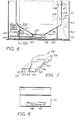
- FIG. 6 is a vertical sectional view of the lower portion of the heavy-duty dishwashing machine taken perpendicularly to the view in FIG. 1, and discloses the means for separating the granules from the liquid ejected from the nozzles, and for storing the granules;
- FIG. 7 is a perspective view of a cassette for receiving and storing the granules; and
- FIG. 8 is a fragmentary view taken along line VIII - VIII in FIG. 6 and illustrates the cassette in end view as seen towards the end of the cassette, which opens into the pump chamber.
- The heavy-duty dishwashing machine comprises an
outer cassette 10 in which atreatment chamber 12 for the goods to be washed is bounded by means ofinside walls 11. For the supply of the goods to be washed, supported on acarriage 13, to this treatment chamber there is provided in connection with anentrance 14 which can be closed by means of doors not shown, - a carriage elevator by means of which the carriage can be lifted from the floor level and can be displaced into the treatment chamber. The carriage elevator comprises a
cradle 15 which can be displaced hydraulically on ahorizontal support rail 16 arranged centrally at the top of the treatment chamber said rail projecting from the treatment chamber through theentrance 14. Thecradle 15 supports a vertically mountedguide rail 17 on which across-formed lift slide 18 can be displaced hydraulically up and down. The lift slide has a number ofhooks 19 to engage from belowbrackets 20 on thecarriage 13 when thecradle 15 is in an outer end position on thesupport rail 16 and the lift slide is in a lower end position on theguide rail 17 and is then displaced upwardly to lift the carriage sufficiently to the position indicated by dot and dash lines so that the carriage clears thesill 21 in theentrance 14 at succeeding displacement of the carriage elevator and the carriage suspended thereon into thetreatment chamber 12 from the outer end position to an inner end position shown by dot and dash lines in FIG. 1, by thecradle 15 being displaced along thesupport rail 16. Anabutment 22 is provided on theguide rail 17 to support thecarriage 13 when suspended from. the carriage elevator. - The arrangement described provides a rational handling of the goods to be washed because this goods can be shelved on the carriage at different collecting places and then easily can be moved into the heavy-duty dishwashing machine without substantial manual work, but it is of course also possible to arrange the heavy--duty dishwashing machine with shelves or guides for the insertion of baskets and racks manually into the treatment chamber.
- The lower portion of the
cabinet 10 is formed as aliquid container 23 below thetreatment chamber 12, and this liquid container is enlarged to form a closedsuction chamber 24 to which apump 25 driven by an electric motor is connected with the suction side thereof. The pressure side of the pump is connected to apressure conduit 26 which in turn is connected bydistribution conduits 27 to a number ofnozzles 28 rotatably mounted in two vertical rows on two opposite side walls of the treatment chamber inniches 29 formed by these side walls. The connection between thenozzles 28 which are cranked, and thedistribution conduits 27 is provided bypivot couplings 30. For the rotation of the nozzles these are provided withsprockets 31, and anendless chain 32 engages these sprockets said chain also running over two conductingsprockets 33 at the top. One of these conducting sprockets is connected to anelectric drive motor 34. It will be seen that thechain 32 is extended alternatingly at one side and the other of thesprockets 31 so that thenozzles 28 in a row are driven alternatingly in one direction and the other. - The
treatment chamber 12 has abottom 35 which is perforated to the extent it covers theliquid container 23. It slopes as a funnel towards acentral opening 36 covered by agrid 37. Thetreatment chamber 12 communicates with the.liquid container through theopening 36, not directly but via acassette 38 shown separately in FIG. 7. The cassette is connected to theopening 36 at asquare socket 39 and aconduit portion 40 of the cassette, having the same width as the socket, extends through theside wall 41 of thecontainer 23 into the closedsuction chamber 24 wherein it opens. Thecassette 38 is arranged to be easily removable from the heavy--duty dishwashing machine by being lifted at thesocket 39 and being withdrawn through the opening 36. It serves as a magazine for the granules used as an addition to the liquid to provide a mechanical working of the goods to be washed by liquid blasting. The perforation of thebottom 35 consists of sufficiently small openings so as not to let through the granules as long as they are not worn due to the use thereof in the machine to such extent that they are no longer effective for the purpose thereof while thegrid 37 on the contrary has sufficiently large openings to let through unobstructedly the granules to thecassette 38. - The
conduit portion 40 of thecassette 38 has an upper boundingwall 42 which extends over the entire width of the cassette. By means of apartition wall 43 extending angularly through theconduit portion 40 there is defined apassage 44 the opening of which at the end connected to thesocket 39 has the same width as the conduit portion while the opening at the other end indicated at 45 and opening into thesuction chamber 24 has a width which is only half the said width. Gillopenings 46 possibly covered by a close--meshed netting to retain the granules in the cassette are provided in the side walls of thesocket 39 and thepassage 44 such that water can pass between the interior of thecassette 38 and theliquid container 23. - The
partition wall 43 also defines apassage 47 in theconduit portion 40, which is open at the bottom- thereof and also opens into thesuction chamber 24 through an opening 48 of the same size as theopening 45. Aplate valve 49 is displaceable on ahorizontal bar 50 and is of a size to cover completely only one of theopenings bar 50. In intermediate positions the valve covers each opening more or less. Means can be provided for displacement of thevalve 49 manually or by means of a servo on thebar 50 but such means which can be of a known construction are not shown here. - If it is assumed that the
liquid container 23 contains liquid and that the granules to be added to the liquid from the beginning are contained in the.cassette 38 the opening 48 of which is assumed to be closed while theopening 45 is open, granules will be carried by the liquid when this is sucked-up by thepump 25 from thesuction chamber 24 because thesuction chamber 24 is connected to theliquid container 23 through thepassage 44 of the.cassette only. Due to the fact that the liquid then will flow into thepassage 44 from the sides through thegill openings 46 the granules will be agitated by turbulence of the liquid and will be carried away by the liquid flow to the pump without being'packed in thepassage 44. The liquid containing granules is expelled from thenozzles 28 at the pressure side of the pump and is thrown towards the goods to be washed on thecarriage 13 in order to provide the cleaning effect thereof. Liquid and granules as well as accompanying contaminants then fall down to thebottom 35 of thetreatment chamber 12 where liquid and granules are separated. The granules pass through thegrid 37 and theopening 36 into thecassette 38 where they are again carried away by the liquid as this is being sucked-up by thepump 25 from thecontainer 23 via thesuction chamber 24. - The advantage of arranging the supply of the granules to the liquid in this manner is above all, as mentioned above, that there will be no accumulation of packed granules, which could prevent the circulation of the liquid, but also that the addition of granules can be controlled and can be brought to cease completely. If the
valve 49 is displaced to the end position in which the valve covers theopening 45 the pump will draw liquid only from thecontainer 23 through thepassage 47 and thesuction chamber 24, and with the valve in positions between said two end positions granules will be mixed with the liquid more or less. The adjustment of the valve is preferably controlled from a timer which controls also other functions of the heavy-duty dishwashing machine. - When the
pump 25 is sucking liquid through thepassage 47, the liquid is forced to pass from thecontainer 23 below thelower edge 51 of the side wall of thecassette 38, bounding t.he passage 47, and it is - prevented thereby that air will be sucked-in by the pump. - The granules used in the heavy-duty dishwashing machine according to the invention preferably consist of plastics material such as Nylon or Delrin. The granules need not be spherical but can have any form; they can comprise for instance small polyhedrons or cylinders. The substantially spherical form is preferred,however, because balls have no tendency of adhering to the goods to be washed in the manner that can occur as far as granules with plane surfaces are concerned. As guidance for the dimensioning of the granules and the adjustment of other factors affecting the cleaning action of the granules the following specification is given:
- Mass of the granules max.. 0.2 g
- Size of the granules 0.5-5 mm
- Spec. gravity of the granules 0.8-1.9
- Velocity of the granules from
- the nozzles 4-35 m/sec
- Nozzle area 0.3-3 cm2
- The amount of granules should comprise between 10 and 50 per cent by volume of the circulating liquid and preferably should be 20 to 40 per cent by volume.
- Excellent results have been obtained by granules formed as substantially spherical bodies of Delrin having a diameter of substantially 3 mm when washing such heavily soiled goods as exist in catering centers and restaurants and comprise stainless utensils such as trays, pans, dish-plates, etc. where the existing radius of curvature practically never is less than 3 mm. When impigning against such goods balls having a diameter of 3 mm can enter into and work also the smallest existing nooks and corners of the goods.
- The following values of the parameters given above, which have been obtained from experience, have been found to provide optimum cleaning action when Delrin balls having a diameter of 3 mm, are being used:
- The mass of the balls 0.01946 g
- The spec. gravity of the balls 1.40
- Velocity 13.18 m/sec
- Nozzle area 1.267 cm
- Amount of
balls abt 35 per cent by volume - Since the cleaning in the heavy-duty dishwashing machine according to the invention is effected by the simply mechanical effect on food residues adhering to the goods to be washed the temperature of the circulating liquid can be kept low without any detrimental effect on the result; on the contrary, a low temperature is advantageous because it is thereby avoided that proteins in the food residues coagulate and adhere still firmer to the goods. By means of the granules the food residues are broken and comminuted so that they can be easily removed by the circulating liquid.
- A typical dishwashing program in the heavy-duty dishwashing machine according to the invention can comprise the following different steps:
- 1. Prerinsing at about 38°C without granules for 30 sec.
- 2. Dishwashing with granules at 38°C for 3 to 10 min.
- 3. Final rinsing at 380C without granules for 30 sec for returning the granules to the
cassette 38 theopening 45 being closed. - 4. Final flushing at 90°C without granules for 15 sec for disinfection of the goods and for facilitating.. draining and drying.
- When liquid containing granules is being circulated friction heat is generated to some extent by the granules impigning against the goods to be washed, and in the dishwashing cycle described this friction heat can be sufficient in order to maintain the temperature at about 38°C if the liquid supplied has substantially this temperature from the beginning.
- In the steps 1 to 3 the same liquid can be used for the dishwashing. For cleaning this liquid between the steps the dishwashing machine can be provided with a
hydrocyclone 52 which is connected at the inlet side thereof to aconduit 53 which communicates with thepressure conduit 26, and is connected at the outlet side thereof to aconduit 54 opening into thetreatment chamber 12 so that liquid without granules can be pumped through the hydrocyclone between the steps 1 and 2 and between the steps 2 and 3, respectively, or part of the liquid can be pumped continuously through the hydrocyclone during the steps 1 and 3. In the cyclone entrained food residues are separated and discharged to adrain 55. After the step 3 the liquid is discharged to the drain and then fresh, clean liquid at the temperature 90°C is supplied for the final flushing. All these operations can be controlled from the timer by means of solenoid valves.
Claims (7)
1. Cleaning machine with means for blasting the goods to be cleaned by means of liquid containing granules, characterized in that the granules have a size between 0.5 and 5 mm.
2. Cleaning machine according to claim 1, characterized in that the granules have a size of about 3 mm.
3. Cleaning machine according to claim 1 or 2, characterized in that the granules have a specific gravity between 0.8 and 1.9.
4. Cleaning machine according to claim 3, characterized in that the granules have a specific gravity of about 1.4.
5. Cleaning machine according to any of claims 1 to 4, characterized in that the granules have a maximum mass of 0.2 g.
6. Cleaning machine according to claim 5, characterized in that the granules have a mass of about 0.03 g.
7. Cleaning machine according to any of claims 1 to 6, characterized in that the granules consist of a plastic material.
Priority Applications (1)
| Application Number | Priority Date | Filing Date | Title |
|---|---|---|---|
| EP82200109A EP0057044A3 (en) | 1979-04-02 | 1979-04-02 | Cleaning machine |
Applications Claiming Priority (1)
| Application Number | Priority Date | Filing Date | Title |
|---|---|---|---|
| EP82200109A EP0057044A3 (en) | 1979-04-02 | 1979-04-02 | Cleaning machine |
Related Parent Applications (2)
| Application Number | Title | Priority Date | Filing Date |
|---|---|---|---|
| EP19790850019 Division EP0016895B1 (en) | 1979-04-02 | 1979-04-02 | Cleaning machine |
| EP79850019.5 Division | 1979-04-02 |
Publications (2)
| Publication Number | Publication Date |
|---|---|
| EP0057044A2 true EP0057044A2 (en) | 1982-08-04 |
| EP0057044A3 EP0057044A3 (en) | 1982-08-11 |
Family
ID=8189457
Family Applications (1)
| Application Number | Title | Priority Date | Filing Date |
|---|---|---|---|
| EP82200109A Withdrawn EP0057044A3 (en) | 1979-04-02 | 1979-04-02 | Cleaning machine |
Country Status (1)
| Country | Link |
|---|---|
| EP (1) | EP0057044A3 (en) |
Cited By (1)
| Publication number | Priority date | Publication date | Assignee | Title |
|---|---|---|---|---|
| WO1984003616A1 (en) * | 1983-03-24 | 1984-09-27 | Mosell Carl G C | Method in a cleaning machine and a cleaning machine for working the method |
Family Cites Families (5)
| Publication number | Priority date | Publication date | Assignee | Title |
|---|---|---|---|---|
| US1761492A (en) * | 1928-03-06 | 1930-06-03 | Frank B Reily | Bottle-washing machine |
| AT165716B (en) * | 1947-06-04 | 1950-04-11 | ||
| DE1148360B (en) * | 1958-04-21 | 1963-05-09 | Orlando Mori | Dishwasher |
| US3012262A (en) * | 1958-04-21 | 1961-12-12 | Mori Orlando | Washing machine for dishes |
| US3323159A (en) * | 1964-12-10 | 1967-06-06 | Gen Motors Corp | Dishwasher with particle reclaiming |
-
1979
- 1979-04-02 EP EP82200109A patent/EP0057044A3/en not_active Withdrawn
Cited By (1)
| Publication number | Priority date | Publication date | Assignee | Title |
|---|---|---|---|---|
| WO1984003616A1 (en) * | 1983-03-24 | 1984-09-27 | Mosell Carl G C | Method in a cleaning machine and a cleaning machine for working the method |
Also Published As
| Publication number | Publication date |
|---|---|
| EP0057044A3 (en) | 1982-08-11 |
Similar Documents
| Publication | Publication Date | Title |
|---|---|---|
| EP0087566B1 (en) | Cleaning machine | |
| US7748393B2 (en) | Apparatus and method for cleaning, drying and sanitizing produce | |
| KR940011551B1 (en) | dish washer | |
| EP1778067B1 (en) | Conveyor-type dishwasher and method for operating it | |
| CA2817244A1 (en) | Conveyor dishwasher | |
| EP1765135B1 (en) | Conveyor-type dishwasher and method for operating it | |
| EP0016895B1 (en) | Cleaning machine | |
| KR100610139B1 (en) | dish washer | |
| EP0057044A2 (en) | Cleaning machine | |
| CA1140425A (en) | Cleaning machine with blasting means | |
| CN218915798U (en) | Fresh goods drying equipment | |
| EP3773119B1 (en) | Warewash machine with submersible cutlery basket | |
| JP2019134845A (en) | Dishwasher | |
| CN212438327U (en) | Kitchen equipment and steaming, baking and washing integrated machine | |
| WO2001037956A1 (en) | A method of operation of a ball machine and a ball machine | |
| JP2019080605A (en) | dishwasher | |
| JP2001190475A (en) | Dishwasher | |
| CN213606191U (en) | Novel dish washing machine | |
| CN210520920U (en) | Tableware recycling all-in-one machine | |
| EP4640129A1 (en) | Dishwasher | |
| JP4171367B2 (en) | Dishwasher filter and dishwasher | |
| KR20090058162A (en) | Knife Storage Case for Dishwasher | |
| JP3773637B2 (en) | Dishwasher | |
| JPH10192071A (en) | Washing device | |
| JPH01160521A (en) | Washer for lunch box or the like |
Legal Events
| Date | Code | Title | Description |
|---|---|---|---|
| PUAI | Public reference made under article 153(3) epc to a published international application that has entered the european phase |
Free format text: ORIGINAL CODE: 0009012 |
|
| PUAL | Search report despatched |
Free format text: ORIGINAL CODE: 0009013 |
|
| AC | Divisional application: reference to earlier application |
Ref document number: 16895 Country of ref document: EP |
|
| AK | Designated contracting states |
Designated state(s): BE CH DE FR GB IT NL SE |
|
| AK | Designated contracting states |
Designated state(s): BE CH DE FR GB IT NL SE |
|
| 17P | Request for examination filed |
Effective date: 19830203 |
|
| STAA | Information on the status of an ep patent application or granted ep patent |
Free format text: STATUS: THE APPLICATION IS DEEMED TO BE WITHDRAWN |
|
| 18D | Application deemed to be withdrawn |
Effective date: 19880202 |