EP1765135B1 - Conveyor-type dishwasher and method for operating it - Google Patents
Conveyor-type dishwasher and method for operating it Download PDFInfo
- Publication number
- EP1765135B1 EP1765135B1 EP05755553A EP05755553A EP1765135B1 EP 1765135 B1 EP1765135 B1 EP 1765135B1 EP 05755553 A EP05755553 A EP 05755553A EP 05755553 A EP05755553 A EP 05755553A EP 1765135 B1 EP1765135 B1 EP 1765135B1
- Authority
- EP
- European Patent Office
- Prior art keywords
- rinse
- final
- wash
- items
- cleaned
- Prior art date
- Legal status (The legal status is an assumption and is not a legal conclusion. Google has not performed a legal analysis and makes no representation as to the accuracy of the status listed.)
- Expired - Fee Related
Links
Images


Classifications
-
- A—HUMAN NECESSITIES
- A47—FURNITURE; DOMESTIC ARTICLES OR APPLIANCES; COFFEE MILLS; SPICE MILLS; SUCTION CLEANERS IN GENERAL
- A47L—DOMESTIC WASHING OR CLEANING; SUCTION CLEANERS IN GENERAL
- A47L15/00—Washing or rinsing machines for crockery or tableware
- A47L15/24—Washing or rinsing machines for crockery or tableware with movement of the crockery baskets by conveyors
- A47L15/247—Details specific to conveyor-type machines, e.g. curtains
-
- A—HUMAN NECESSITIES
- A47—FURNITURE; DOMESTIC ARTICLES OR APPLIANCES; COFFEE MILLS; SPICE MILLS; SUCTION CLEANERS IN GENERAL
- A47L—DOMESTIC WASHING OR CLEANING; SUCTION CLEANERS IN GENERAL
- A47L15/00—Washing or rinsing machines for crockery or tableware
- A47L15/24—Washing or rinsing machines for crockery or tableware with movement of the crockery baskets by conveyors
- A47L15/241—Washing or rinsing machines for crockery or tableware with movement of the crockery baskets by conveyors the dishes moving in a horizontal plane
Description
- The present application relates to a dishwasher operating method and to a conveyor-type dishwasher with at least one wash zone and a final-rinsc zone.
- Among the machines used as commercial dishwashers are front-loading machines, rack push-through machines and conveyor-type dishwashers, while under-counter dishwashers are generally used in the domestic sector. The loading of front-loading machines with dish racks in which the dishes are held and the removal of the dish racks from front-loading machines takes place from the front. In the case of rack push-through machine, the dish racks, laden with ditty dishes, are manually pushed into the machine from a feeding side and, after completion of the cleaning program, are manually removed from the machine from a delivery side. Conveyor-type dishwashers, which are distinguished in comparison with the previously mentioned types of dishwasher by a high throughput of items to be washed per unit of time, have at least one spray zone, but usually more than one spray zone, through which the items to be cleaned are automatically conveyed.
- In each spray zone of a conveyor-type dishwasher, at least one spray operation can be executed. In the case of conveyor-type dishwashers, it is generally customary for the dishes to be cleaned of major soil in a first spray zone (pre-wash zone) by spraying with a dishwashing detergent solution, while thorough cleaning of the dishes takes place in a subsequent spray zone (wash zone) by renewed spraying with a dishwashing detergent solution. Thereafter follows at least one, mostly two spray zones (rinse zones) in which dishes are sprayed with a rinse aid solution, in order to finally rinse the dishes completely clear of dirt particles and clear of dishwashing detergent solution. The final-rinse operation is generally carried out at temperatures of 80 °C to 85 °C, before the dishes are then conveyed into a drying zone for drying.
- A conveyor-type dishwasher with four spray zones is described in
U.S. Patent No. 3,598,131 . The spray zones are designed as a pre-wash zone, as a wash zone, as a rinse zone and as a final-rinse zone, the items to be cleaned being conveyed continuously through these spray zones one after another in suitable dish racks. The individual zones are separated from one another by suspended flexible "curtains". In the pre-wash zone, a solution at about 49 °C is sprayed onto the items to be cleaned by means of spray nozzles, in order to remove particles of food from the items to be cleaned. Subsequently, in the wash zone, a mixture of water and dishwashing detergent at about 66 °C and in turn, subsequently in the rinse zone, hot water at temperatures of about 77 °C is sprayed onto the items to be cleaned by means of spray nozzles. To achieve disinfection of the items to be cleaned, in the final-rinse operation, hot water at about 82 °C is sprayed onto the items to be cleaned by means of spray nozzles in the final-rinse zone. - A similar conveyor-type dishwasher, likewise with four spray zones, is known from
U.S. Patent Nos. 3,789,860 .U.S. Patent No. 3,789,860 describes a pre-wash zone, in which larger particles of food are removed, a subsequent main wash zone for accomplishing effective cleaning of the items to be cleaned, a main-rinse zone and, finally, a final-rinse zone. The temperature in the dishwasher is approximately 46 °C in the first zone and increases zone by zone up to a temperature of approximately 82 °C in the final-rinse zone. - The device of
U.S. Patent No. 4,231,806 is suitable for dishwashers with a number of spray zones and describes means for creating a barrier in the form of a fluid curtain, a fluid curtain preferably being created respectively at the entry and exit of a wash zone and at the entry and exit of a final-rinse zone. The fluid curtain at the entry and exit of the wash zone greatly reduces the escape of vapour from the wash zone. - In the medical sector,
U.S. Patent No. 6,632,291 discloses methods for the washing, rinsing and/or antimicrobial treatment of medical instruments, equipment, transporting carts and animal cages. Washing takes place at temperatures between 30 °C and 80 °C, preferably between 35 °C and 40 °C, while usually -rinse is carried out at temperatures between 40 °C and 80 °C and a final-rinse is carried out at increased temperatures at approximately 80 °C to 95 °C. The antimicrobial treatment is performed with an antimicrobial agent. The method described can be carried out automatically in a wash apparatus which has a number of stations. -
U.S. Patent No. 4,788,992 describes an ultrasonic cleaning method and an apparatus for carrying out ultrasonic cleaning of elongated strip material. After the ultrasonic cleaning, the strip material is sent past dewatering blowers and subsequently past spray nozzles of a number of rinse chambers, before it is heated and dried in a final step. -
U.S. Patent No. 6,354,481 relates to the processing of electronic components and in particular to a compact apparatus for remelting and subsequently cleaning electronic components, in particular BGA components. The cleaning zone has a wash zone and a rinse zone, and a hot-air blower may also be arranged downstream of them, whereby temperatures in the wash zone are at 49 °C to 71 °C and in the rinse zone at 49 °C to 99 °C. -
U.S. Patent No. 2,235,885 describes an apparatus for washing (cleaning) and disinfecting glassware, the apparatus having a chamber which can be tightly closed for the spray operation. Within the chamber, positioning carriers are provided for holding the glassware to be cleaned. Also arranged in the chamber, underneath the positioning carriers, are tubes with upwardly directed spraying means and, in the upper part of the chamber, there are tubes with downwardly directed openings, which are fed with hot water, cold water or steam through corresponding supply lines. The feeding in of hot water and steam into the pipework is manually set by means of a hot-water valve, and the feeding in of cold water into the pipework is manually set by means of a cold-water valve. - In the case of washing operation described in
U.S. Patent No. 2,235,885 , glassware to be cleaned is first rinsed and disinfected with hot water and steam in the chamber. Subsequently, a cold-water valve is progressively opened and, after the cold-water valve has been opened, the hot-water valve is closed, so that then only cold water is introduced into the chamber and the glassware to be cleaned is chilled with cold water in the final-rinse operation. - In
U.S. Patent No. 4,070,204 a washing method is described which can be carried out in a dishwasher which includes a cleaning chamber into which cold water, hot water or a combination of both can be introduced optionally. The washing method begins with at least one cold pre-wash, which is followed by a hot wash. Subsequently, a cold-water rinse and at least one hot-water final-rinse are carried out. - Document
DE-A-2 712 020 describes a method and a conveyor type dishwasher according to the preamble of claims 1 and 7, whereby a steam desinfection occurs. - The development of dishwashers and dishwashing methods, in particular in the commercial sector, is dominated today by the objective of energy and water conservation, which is becoming increasingly important for environmental reasons. Nevertheless, in particular in the case of commercial dishwashers, the throughput, which is the amount of items cleaned per unit of time, and the washing quality should not be deteriorated. The working conditions of the operator of a dishwasher are also considerably impaired in the region of the dishwasher by vapours which escape, with the result that an improvement in this area is also desirable.
- Furthermore, apart from thorough cleaning, disinfection of the items to be cleaned should also be carried out. In the field of dishwasher technology, disinfection means killing micro-organisms at a level that is neither harmful to health nor impairs the quality of food. In the case of some wash methods, disinfection is achieved by the use of chemical disinfection components, but this has disadvantages from aspects concerning the environment and safety at work. Disinfection by adequately intense heating of the items to be cleaned is also known.
- It would be desirable to provide an improved operating method and an improved conveyor-type dishwasher of the type as indicated which - while maintaining high cleaning quality - have in particular low energy and water consumption, are sufficiently productive and can be used without reservations from aspects concerning the environment and safety at work.
- A conveyor-type dishwasher and related methods may be provided with one or more features to assist in low energy and/or water consumption, including one or more of (i) executing final-rinse of items with a consumption of final-rinse liquid that is 3.5 l/min or less; (ii) executing final-rinse of items with a consumption of final-rinse liquid of 3 l/m2 movement of the horizontal take-up plane of a dish carrier or less; (iii) executing final-rinse of items with one or more side-originating final-rinse liquid spray jets in combination with top-originating final-rinse liquid spray jets and bottom-originating final-rinse liquid spray jets; (iv) prior to a final rinsing step executing a cleaning operation or a subsequent hot post wash and/or a rinsing step using filtered and/or regenerated washing or rinsing solution that is produced from a used washing or rinsing solution in dependence on a contamination dependent or time dependent control signal; (v) subsequent to a final-rinse operation, passing items through a cold-water curtain; (vi) between a wash operation and a final-rinse operation, subjecting items to the action of steam; and (vii) after a wash operation, providing a hot post-wash operation using hot post-wash liquid that has a higher temperature than a final-rinse liquid.
-
-
Fig. 1 is a schematic longitudinal sectional representation of a conveyor-type dishwasher according to a first embodiment, -
Fig. 2 is a schematic longitudinal sectional representation of a conveyor-type dishwasher according to a second embodiment, -
Fig. 3 is a schematic longitudinal sectional representation of a conveyor-type dishwasher according to a third embodiment, -
Fig. 4 is a schematic longitudinal sectional representation of a conveyor-type dishwasher according to a fourth embodiment, -
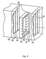
Fig. 5 is a schematic longitudinal sectional representation of a conveyor-type dishwasher according to a fifth embodiment, which is the embodiment of the invention, -
Fig. 6 is a schematic front view of a final-rinse zone of a conveyor-type dishwasher according toFig. 1 , -
Fig. 7 is an arrangement of final-rinse nozzles modified in comparison withFig. 6 , wherein the centre part a) shows a front view, the left side part b) shows a side view, and the upper part c) shows a top view of the arrangement of the final-rinse nozzles, -
Fig. 8 is a schematic longitudinal sectional representation of a conveyor-type dishwasher according to a sixth embodiment of the invention, -
Fig. 9 is a schematic perspective representation of a zone for subjecting the items to be cleaned to the action of steam in a conveyor-type dishwasher of a seventh embodiment, -
Fig. 10 is a schematic representation in the form of a functional block diagram to explain controlled filtering or regeneration of used rinse solutions, and -
Fig. 11 is a diagram with temperature profiles. - One proposed method comprises at least one wash operation, that is to say spraying with a dishwashing detergent solution for thoroughly cleaning remains of food from the items to be cleaned, a so-called hot post-wash, and at least one final-rinse, preferably with a rinse aid solution for rinsing off all dirt particles and dishwashing detergent solution from the items to be cleaned. Dishes, cutlery, forks, spoons, knifes and trays are regarded as items to be cleaned. Dishwashing detergent solution is water enriched with a dishwashing detergent, whereby the addition of the dishwashing detergent promotes thorough removal of remains of food from the items to be cleaned and counteracts renewed soiling of the items by the dishwashing detergent solution. The final-rinse aid solution is generally clean water mixed with a rinse aid, whereby the interfacial tension of the rinse aid solution is reduced by the rinse aid, to that optimum wetting of the cleaned items is achieved.
- An important idea in this respect is that, in the case of conveyor-type dishwashers, high-temperature dishwashing operations, that is to say wash or rinse operations, are to be carried out in a central region of the machine, whereas low-temperature wash or rinse operations are to be carried out in the region of the entry or exit of the machine. This produces a temperature profile which drops from a maximum value in a central region towards the outer regions. By contrast, in the case of the previously known conveyor-type dishwashers, the temperature profile increases to the maximum value in the region of the exit, since disinfection of the items to be washed only takes place in the final-rinse operation at temperatures of 80 °C to 85 °C. In the prior art, the preceding wash operations are carried out at temperatures around or below 70 °C.
- The novel temperatures profile has the effect of keeping energy losses low, since an escape of heat and vapour from the central region is suppressed by the two adjacent regions, and condensing of the vapour in the cooler outer regions is promoted. The heat of condensation can therefore still be used within the conveyor-type dishwasher.
- Accordingly, hot post-wash may be performed with a high water temperature and, after that, final rinsing may be performed with a lower water temperature. The high water temperature during the hot post-wash operation is preferably higher than 70 °C, so that a disinfection of the items to be cleaned is achieved, and the lower water temperature during the final-rinse operation is preferably lower than 65 °C and more preferably lower than 60 °C, so that condensing is promoted by the temperature reduction. The hot post-wash operation may be carried out according to choice as a wash operation, that is with a dishwashing detergent solution, or as a final-rinse operation, that is with a rinse aid solution.
- Furthermore, the items to be cleaned may be subjected to a significantly greater amount of wash solution during the hot post-wash operation than during the subsequent final-rinse operation, with the result that in the hot post-wash step a high level of heat application to the dishes is also realized by means of a high overall thermal capacity of the solution to which they are subjected. In particular, a hot post-wash solution throughput in the range between 5 and 30 l/min, preferably between 10 and 20 l/min, is provided during the hot post-wash operation, while the consumption of final-rinse aid solution is intended to be significantly less than half of that (preferably 2 to 3 l/min).
- Also in the case of dishwashers with only one cleaning chamber, the heat of condensation, which is released in particular during the final-rinse operation with a lower water temperature, can be used. Furthermore, the escape of steam when the dishwasher is opened is reduced by the preceding condensation, so that the method is also advantageous for such dishwashers.
- The final-rinse operation may advantageously be carried out at a temperature of the rinse aid solution in the range between 25 °C and 65 °C, preferably between 25 °C and 60 °C. In this temperature range, the temperature reduction in comparison with the preceding hot post-wash operation may be great enough to promote condensation, but excessive cooling of the items to be washed may also be prevented. Excessive cooling of the dishes and wasting of clean water may also be avoided if the final-rinse operation is executed at least partly in a spray mist. Furthermore, the finely distributed droplets of the spray mist can promote condensation of the vapour. The escape of vapour from the conveyor-type dishwasher may be reduced by the items to be cleaned passing through a cold-water curtain, in particular in the form of a cold-water spray mist, following the final-rinse operation.
- If the hot post-wash operation is performed directly before the final-rinse operation at a water temperature in the range between 80 °C and 90 °C, in particular at 85 °C, only short contact times are necessary to achieve adequate disinfection of the items to be cleaned, on account of the high temperature level. Preferably, a wash operation at a water temperature of 65 °C is carried out before the hot post-wash operation, in order to get an effective cleaning of the dishes with relatively short contact times.
- At least one rinse operation can also be performed under steam. If the items to be cleaned are subjected to the action of steam between the hot post-wash operation and the final-rinse operation, the level of heat transfer into the items to be cleaned is increased, and accordingly disinfection of the items is assisted. The introduction of steam also has the advantageous effect that is keeps down the evaporation losses, in particular during the wash operation and the hot post-wash operation.
- Filtered and/or regenerated final-rinse aid solution may be used for executing the hot post-wash and/or a wash operation. Using already used final-rinse aid solution also for the hot post-wash and/or for a wash operation successfully reduces the amount of clean water required. Filtering the final-rinse aid solution which was already used and/or regenerating it with clean water has the effect of keeping down the consumption of clean water while maintaining the cleanness of the dishwashing detergent solution or final-rinse aid solution, in particular whenever the filtering and/or regeneration is carried out in dependence on the turbidity of the solution. This can reduce or prevent re-soiling of the items to be cleaned.
- A further feature is to reduce the water consumption for the final-rinse operation, in comparison with the prior art, by a differentiated nozzle arrangement. Whereas in the case of the nozzle arrangements previously used in the final-rinse operation, with only upper and lower nozzles, a relatively strong spray jet of the individual nozzles was required, since concealed surface areas of the items to be cleaned were only reached by deflected spray jets, an advantageous nozzle arrangement with greater differentiation of the spray directions allows a large part of the surface areas of the items to be cleaned to be reached directly. Therefore, the final-rinse operation can be carried out with reduced water throughput. In particular in combination with the hot post-wash operation described above, a low water throughput during the final-rinse operation at lower temperatures has the advantageous effect that cooling of the items to be cleaned during the final-rinse operation is minimized as much as possible. This may even allows drying with blower air of a lower temperature (<50 °C) to be carried out after the final-rinse operation, since the still elevated temperature of the items assists drying of them.
- Specifically, the final-rinse operation may be executed with the items to be cleaned being subjected to the action of final-rinse aid solution from at least three sides of a final-rinse zone, to be precise from the floor and from the ceiling surface and from at least one side wall. A large part of the surface areas of the items to be cleaned is then reached directly. Advantageously, the nozzles may be arranged on the side wall/side walls in such a way that the feeding of the final-rinse aid solution from the side walls takes place in each case at four positions in the central height region of the final-rinse zone, two of which in particular are positioned respectively close to each other. The nozzles on the floor and on the ceiling surface may be arranged in such a way that the feeding of the final-rinse aid solution from the floor and from the ceiling surface proceeds from five points of the floor and four positions of the ceiling surface of the final-rinse zone, which are respectively arranged essentially equidistant from one another and from the side walls. In order to achieve reduced use of water during rinsing, the final-rinse operation may be executed in spray mist with a consumption of final-rinse aid solution of 3.5 l/min or less, in particular of 2 l/min - 3 l/min for a rinse capacity of typically 2500-5000 plates per hour or a comparable throughput of other items to be cleaned.
- With regard to the apparatus, a conveyor-type dishwasher, in particular a multi-tank conveyor-type dishwasher, comprising several spray zones; a conveying device for conveying items to be cleaned through the spray zones; water feeds assigned to the spray zones for feeding dishwashing detergent solution and final-rinse aid solution respectively and for subjecting the items to be cleaned to them; and also means assigned to at least some of the water feeds for setting the temperature of the respective wash or rinse solution.
- The conveying device for conveying items to be cleaned may take different forms; it may be designed as a dish conveyor belt, chains, or latching bars. The means for temperature setting may be designed either as controllable heaters in a reservoir of the spray solution, or else they may be formed simply by the systems of tubes which lead to a reservoir of the rinse solution. The term spray solution refers both to dishwashing detergent solution and to a final-rinse aid solution.
- A conveyor-type dishwasher according to one aspect is characterised in that means are provided for setting the water temperature in a hot rinse operation (hot post-wash operation) to a first temperature value, in particular more than 70 °C, and for setting the water temperature of a subsequent final-rinse operation to a lower value, in particular less than 65°C or preferably less than 60 °C.
- According to a further apparatus-related aspect, a conveyor-type dishwasher is characterised in that a final-rinse zone is provided which has final-rinse water nozzles on the floor and on the ceiling surface and additional final-rinse water nozzles on at least one side wall.
- Referring now to
Fig. 1 , a conveyor-type dishwasher 2, which is designed for carrying out the operation method explained, is shown in a schematic longitudinal sectional representation. The conveyor-type dishwasher 2 represented has fourspray zones direction 12 of items to be cleaned (not represented) that may be carried by acarrier 13. Items to be washed are conveyed through the conveyor-type dishwasher 2 (from right to left inFig. 1 ) and accordingly through the fourspray zones respective spray zone - In the conveying
direction 12 of the items to be cleaned, the fourspray zones zone 14,blower air 16 is sent by ablower 18 into the dryingzone 14, whereby drying of items to be cleaned is achieved. - In the
pre-wash zone 4, large remains of food are removed from the items to be cleaned by washing with dishwashing detergent solution. Dishwashing detergent solution is fed from apre-wash reservoir 20 by means of a pump not shown and via corresponding lines toupper pre-wash nozzles 22 and lower pre-wash nozzles 24 (which may also be formed as simple openings in the lines). Theupper pre-wash nozzles 22 are arranged in a downwardly directed manner in an upper part of thepre-wash zone 4 and thelower pre-wash nozzles 24 are arranged upwardly directed manner in the lower part of thepre-wash zone 4, so that dishwashing detergent solution is sprayed onto the items to be cleaned that are located in thepre-wash zone 4 from above and from below by thepre-wash nozzles - The pre-wash nozzles 22, 24 and
further nozzles downstream spray zones direction 12, of therespective spray zone nozzles respective spray zone overflow 26 may be provided at thepre-wash reservoir 20, allowing excess dishwashing detergent solution to be transferred from thepre-wash reservoir 20 into a waste-water line. - In the
main wash zone 6, dishwashing detergent solution is fed by means of a pump not shown from amain wash reservoir 28 with an (optional)heating device 29 via corresponding lines to uppermain wash nozzles 30 and to lowermain wash nozzles 32. The uppermain wash nozzles 30 are arranged in a downwardly directed manner in an upper part of themain wash zone 6 and the lowermain wash nozzles 32 are arranged in an upwardly directed manner in a lower part of themain wash zone 6, so that dishwashing detergent solution is sprayed onto the items to be washed in themain wash zone 6 from above and from below by themain wash nozzles - For rinsing the items to be cleaned in the hot
post-wash zone 8, in the embodiment shown, a final-rinse liquid or solution is fed from a heatablehot wash reservoir 34 by means of apump 36 to upper hotpost-wash nozzles 38 and to lower hotpost-wash nozzles 40, by means of which spraying of the items to be cleaned takes place from above and from below in the hotpost-wash zone 8. In the hotpost-wash reservoir 34, which can be heated by means of aheating device 41, a high temperature of the hot solution may be set such that adequate disinfection of the items to be cleaned is achieved by heating the items to be cleaned in the hot spray operation by spraying the items to be cleaned with the hot solution. - The final rinsing in the
final spray zone 10 is carried out with a final-rinse liquid that may include a rinse agent/aid that can be fed directly from the water supply line from a container 42 (heated or unheated) by means of a pump 44 (or by mains water line pressure) to upper and lower final-rinse nozzles, in particular to upper final-rinsenozzles 46 and lower final-rinsenozzles 48, which may be formed as simple openings. Also arranged on the side walls of the final-rinse zone are lateral final-rinsenozzles 50, with which lateral spraying of the items to be cleaned with final-rinse solution can be carried out. As shown, the lateral final-rinsenozzles 50 may be located upstream of the lower and upper final-rinse nozzles. Where spray jets from the lateral nozzles are angled with or against the conveyingdirection 12, such offsetting may aid in limiting or preventing the spray jets of final-rinse liquid from spraying out of the final-rinse zone (e.g., into the dryer zone) and/or out of the machine entirely. An arrangement of the final-rinse nozzles provided by way of example is shown inFig. 6 . - Furthermore,
spray curtains 51 may be provided in the entry and exit regions of the series of the spray zones and between theindividual spray zones different spray zones spray curtains 51 may be designed for example in form of suspended, 10-15 cm wide sheets, which screen off the passages between the individual spray zones. - A
blower 54 in the upper part of the conveyor-type dishwasher 2 sucks vapours upwards in the direction of anoutlet 52, said vapours being passed through aheat exchanger 56 before they reach theextractor 52. Cold tap water is introduced via acorresponding supply line 57 into theheat exchanger 56, in which it is passed in a known way through cooling coils 58, in order to bring about a condensation of the moisture from the vapours which are flowing around the cooling coils. The transferred heat and the heat of condensation of the vapours is used for pre-heating the tap water. Such a heat exchanger for conveyor-type dishwashers is described for example inU.S. Patent No. 3,598,131 . - The tap water preheated in the
heat exchanger 56 is passed via a system oflines buffer storage container 64 into the final-rinsecontainer 42. Furthermore, a rinse aid/agent is added to the clean water to form the final rinsing aid solution. Accordingly, a clean final-rinse liquid or solution, formed from clean water and rinse aid, is used in the final-rinsezone 10. Once it has been used in the final-rinsezone 10, the final-rinse solution is guided into the heatable hotpost-wash zone 8. Some or all of the hot solution used in the hotpost-wash zone 8 is guided viabaffles 66 into the heatablemain wash reservoir 28. A dishwashing detergent is added to the solution in themain wash reservoir 28 to form a dishwashing detergent solution. A first part of the dishwashing detergent solution used in themain wash zone 6 is returned to themain wash reservoir 28, which may be assisted bybaffles 68, and a second part is passed via theoverflow line 70 into thepre-wash reservoir 20. - The
pre-wash reservoir 20, themain wash reservoir 28, the hotpost-wash reservoir 34 and the final-rinsecontainer 42 are designed either as upwardly open reservoirs or else as tanks with an opening or a supply line, through which a solution already used in one of thespray zones reservoirs tanks - Furthermore, a
bypass supply line 72 is provided from the hotpost-wash reservoir 34 into thepre-wash reservoir 20, allowing hot solution to be fed from the hot post -wash reservoir 34 directly into thepre-wash reservoir 20 by means of thepump 36 when avalve 74, which may be designed for example as a solenoid valve, is opened. This may be required in particular when the conveyor-type dishwasher 2 is started for the first time, or if great contamination of the dishwashing detergent solution in thepre-wash reservoir 20 is detected, and consequently regeneration of the dishwashing detergent solution is required. - The
main wash reservoir 28 can also be filled with clean water, preferably with warm clean water, directly via a maincleaning supply line 76 by opening avalve 78, which is preferably designed as a solenoid valve. Such filling via the maincleaning supply line 76 may likewise be required when the conveyor-type dishwasher 2 is started for the first time, or else if great contamination of the dishwashing detergent solution in themain cleaning reservoir 28 is detected, and consequently regeneration of the dishwashing detergent solution in themain wash reservoir 28 is required. - The temperature of the final-rinse liquid in the final-rinse
zone 10 may be reduced considerably in comparison with the temperature of the hot solution in the hotpost-wash zone 8. Accordingly, no heating is generally necessary in the final-rinsecontainer 42, but a heating apparatus may be provided, as is shown by a way of example inFig. 2 (item 43). - The items to be cleaned leave the final-rinse
zone 10 in a still hot state, so that drying with unheated circulating air is sufficient in the dryingzone 14. Accordingly, heating is not required for the final-rinsezone 10 or for the dryingzone 14; in alternative configuration, however, the drying zone and the final-rinse zone may also be heated. - The temperature in the hot
post-wash reservoir 34 may be set by a heating apparatus between 70 °C and 90 °C, preferably at 85 °C. The temperature of the final-rinse aid solution in the final-rinsecontainer 42 lies within a relatively large range, since it depends on whether the clean incoming water used is warm or cold, whether the clean water is passed through theheat exchanger 56 before it is introduced into the final-rinsecontainer 42 and furthermore, whether a heating apparatus is provided in the final-rinsecontainer 42. The lower limit of the temperature range for the final-rinse aid solution in the final-rinsecontainer 42 is that of unheated tap water and the upper limit may be 65 °C or preferably 60 °C. - The temperature of the dishwashing detergent solution in the heatable
main wash reservoir 28 may be about 65 °C or higher. The relatively high temperature allows the flow rate and the pressure with which the dishwashing detergent solution is sprayed onto the items to be cleaned to be kept comparatively low, without causing any deterioration of the dishwashing result. - Since comparatively little clean water is fed into the washing circuit in the case of the conveyor-
type dishwasher 2 shown, there is consequently also a reduction in the amount of dishwashing detergent solution that is fed from themain wash zone 6 into thepre-wash reservoir 20 via theoverflow line 70. Thepre-wash reservoir 20 is not heatable, and, on account of the reduced feeding of dishwashing detergent solution of a higher temperature from themain wash zone 6, a temperature which is considerably lower than the temperature in themain wash reservoir 28 occurs in thepre-wash reservoir 20. It lies between 35 °C and 55 °C, preferably between 40 °C and 50 °C. - A similar effect as in the final-rinse
zone 10 is achieved in thepre-wash zone 4, that is to say that the reduced temperature in comparison with themain wash zone 6 has the effect that vapours which enter thepre-wash zone 4 from themain wash zone 6 are condensed, and consequently the heat of condensation remains within the conveyor-type dishwasher 2 and the escape of vapours into the outside area is suppressed. - In
Fig. 2 to 5 , embodiments which respectively have features that can optionally be realized in addition to the basic embodiment ofFig. 1 are represented by way of example. In this case, not only can each embodiment ofFig. 2 to 5 be combined individually with the basic embodiment fromFig. 1 , but also a number of them together can be combined with it. In the description which follows ofFig. 2 to 5 , only the different or additional features are discussed; for identical features, reference is made to the detailed description ofFig. 1 . - According to the embodiment shown in
Fig. 2 , afilter 84 via which the hotpost-wash nozzles supply line 86. Hot solution is therefore fed from the hotpost-wash reservoir 34 through thepump 36, through thefilter 84 and subsequently to the hotpost-wash nozzles - The
filter 84 allows the hot post-wash operation to be carried out with a relatively clean hot solution, also with the result that relatively clean water is passed on to the precedingwash zones -
Fig. 3 shows afilter arrangement 88, through which dishwashing detergent solution from themain wash reservoir 28 and dishwashing detergent solution from thepre-wash reservoir 20 can be filtered. Via afirst bypass line 90, dishwashing detergent solution from themain wash reservoir 28 is fed by means of apump 92 through thefilter arrangement 88 and back into themain wash reservoir 28. Via asecond bypass line 94, dishwashing detergent solution from thepre wash reservoir 20 is fed by means of apump 96 through thefilter arrangement 88 and back into thepre-wash reservoir 20. In thefilter arrangement 88, there are either separate filters for the dishwashing detergent solution from themain wash reservoir 28 and for the dishwashing detergent solution from thepre-wash reservoir 20 or only one common filter. - In alternatives to the configuration shown here, a filter may either be provided only in or at the pre-wash reservoir or only in or at the main wash reservoir or only in or at the hot post-wash zone. The filter solutions mentioned serve to get a reduction of the extremely small particles (so-called specks) before the items to be cleaned run through the clean-water final-rinse zone. Such extremely small particles may be entrained by a dishwashing detergent solution or by a rinse solution, which is contaminated (even if only slightly), onto the surfaces of the items to be cleaned. The use of filtered rinse solution in the hot post-wash operation described above allows a significant increase in its efficiency, which depends on the contamination of the wash tank(s) and the transfer of dirt from the wash tank/wash tanks into the pre-wash tank.
- In preferred configurations, the filter or filters are designed as cyclone, membrane or piggyback filters, of a structural type of design that is essentially known.
- Furthermore, a
turbidity sensor 98 is provided in themain wash reservoir 28, aturbidity sensor 99 is provide in the hotpost-wash reservoir 34 and aturbidity sensor 100 is provided in thepre-wash reservoir 20, allowing the cleanness of the dishwashing detergent solution to be checked. The amount of dishwashing detergent solution that is fed through the bypass lines 90, 94 is controlled in dependence on the signal of theturbidity sensors - Also in
Fig. 4 , aturbidity sensor 98 is provided in themain wash reservoir 28 and aturbidity sensor 100 is provided in thepre-wash reservoir 20, allowing the cleanness of the dishwashing detergent solution to be checked in a way similar to in the case of theturbidity sensors Fig. 3 . If excessive contamination of the dishwashing detergent solution in themain wash reservoir 28 is established by theturbidity sensor 98, a regeneration of the dishwashing detergent solution is carried out, in that clean water is fed in via the maincleaning supply line 76 by opening thevalve 78. In an analogous way, apre-cleaning supply line 102 is also provided for thepre-wash reservoir 20, allowing clean water to be fed into thepre-wash reservoir 20 by opening avalve 104. Feeding clean water into thepre-wash reservoir 20 is started if excessive contamination of the dishwashing detergent solution in thepre-wash reservoir 20 is established by theturbidity sensor 100. Details of the signal processing are presented further below. - According to the embodiment of the invention which is shown in
Fig. 5 , a nozzle or opening 106 is provided, allowing steam to be introduced in the region between the hotpost-wash zone 8 and the final-rinsezone 10. Via asteam supply line 108, water is fed to aboiler 110, in which the water is heated to about 100 °C, so that in the downstream section of thesteam supply line 108 there is steam, i.e. water vapour at about 100 °C, which is passed on to the nozzle 106. A machine could also be provided with a suitable input point/connector for connecting to an external source of clean steam that might be available at the site of machine installation/use. -
Fig. 6 shows an arrangement of the final-rinse nozzles in the final-rinsezone 10. Four upper (or top-located) final-rinsenozzles 146 are arranged in an upper part of the final-rinsezone 10, their spraying direction being directed essentially downwards. Furthermore, five lower (or bottom-located) final-rinsenozzles 148 are provided in a lower part of the final-rinsezone 10, the spraying direction of which is directed essentially upwards. The lateral (or side-located) final-rinsenozzles zone 10, so that the side-originating spray jets of the lateral final-rinsenozzles lateral rinsing nozzles Fig. 6 by twoplates nozzles 150 and right-hand final-rinsenozzles 152 may be provided. - The upper final-rinse
nozzles 146 are arranged in a row on an upper supply pipe 158 and the lower final-rinsenozzles 148 are arranged in a row on alower supply pipe 160, via which they are supplied with final-rinse solution, the upper supply pipe and lower supply pipe running essentially horizontally and transversely to the conveyingdirection 12. The lateral final-rinsenozzles hand supply pipe 162 or a right-hand supply pipe 164, respectively, via which they are supplied with final-rinse solution, the left-hand supply pipe 162 and the right-hand supply pipe 164 extending essentially vertically and transversely to the conveyingdirection 12. - While in
Fig. 6 the individual final-rinsenozzles direction 12, according to an advantageous embodiment at least some of the final-rinse nozzles are preferably angled slightly in or counter to the conveyingdirection 12 and/or are turned slightly out of the vertical or horizontal alignment. - A correspondingly modified configuration of the final-rinse nozzle arrangement is represented in
Fig. 7 . The reference numerals used there are based in those inFig. 6 . The main difference is that a supply pipe 162' shown on the left side, which is connected to the lower supply pipe 160' via an intermediate piece 163', has lateral final-rinsenozzles 150a', 150b' with different spraying directions. This different alignment can be seen in the side view of the lateral supply pipe 162' in the left-hand part of the figure and, in addition, an angle of 8° is indicated in the plan view in the upper part of the Figure, which is the angle by which the spraying direction of thenozzles 150a' and 150b' respectively is angled clockwise or anticlockwise respectively with respect to the longitudinal extent of the lower supply pipe (and the transverse direction of the machine). This achieves an improved distribution of the final-rinse aid solution over the surfaces of the items to be cleaned, which contributes to reducing the throughput of final-rinse aid solution. In view a) ofFig. 7 the movement direction of the dish carrier is into or out of the page, while in view c) ofFig. 7 the movement direction is up or down relative to such view. - In addition or as an alternative, it may be provided that the lateral final-rinse
nozzles nozzles lateral nozzle 150b' could be oriented to direct its spray jet upward from horizontal as reflected byline 300 and lowerlateral nozzle 150a' could be oriented to direct its spray jet downward from horizontal as reflected by line 302. - The direction of a spray jet emanating from a nozzle is generally determined by a central axis of the spray jet that is output by the nozzle, regardless of whether the spray jet is in the form of a fane, cone, stream or other configuration.
- Nozzles with relatively low throughput, for example with a respective throughput of 0.16 l/min at 0.5 bar, may be used as final-rinse
nozzles Fig. 6 and7 , the total clean water consumption was 2.5 l/min when nozzles with a throughput of 0.15 l/min at 0.5 bar were used. Consequently, the total clean water consumption lies considerably below the value of 3.7 l/min which is customary in the prior art. - The final-rinse nozzles of the final-rinse zone are advantageously designed in such a way that they produce an atomization of the solution into finely distributed droplets, whereby full-coverage rinsing of the items to be cleaned can be achieved with a low delivery rate of solution. In particular in the final-rinse zone, a fine atomization of the rinsing aid solution is also advantageous because the finely distributed droplets promote condensing of the vapours. By providing the lateral nozzles in addition to the typical upper and lower nozzles, a more effective distribution of final-rinse liquid onto items to be cleaned can be obtained, facilitating a reduction in total consumption of final-rinse liquid.
- The invention is not restricted to the embodiments shown by way of example in
Fig. 1 to 6 and the method steps described with respect to them. Rather, the invention is to be understood by overall consideration by a person skilled in the art of the claims, the description, the embodiments that are provided by way of example and the variants mentioned below, which are intended to give a person skilled in the art suggestions for further alternative embodiments, limited by the scope of the claims. - The conveyor-type dishwasher shown in
Fig. 1 to 5 may be designed in various ways, in particular various conveying mechanisms by means of which items to be cleaned are conveyed through the machine can be realized. - A carrier for accommodating items to be cleaned, in particular dishes, may be designed for example as a dish conveying belt in the form of an endless belt, which has a suitable structure, so that is can be loaded with individual items to be cleaned and the individual items can then be held in the most optimum possible rinsing position, in which the largest possible surface of the individual items is reached by the dishwashing detergent solution and the final-rinse aid solution. The conveyor-type dishwasher may accordingly be designed as a conveyor-belt dishwasher, in which items to be cleaned are automatically conveyed on the dish conveying belt through the various rinse zone and through a downstream drying zone.
- Furthermore, the conveyor-type dishwasher may also be designed as a rack-conveying dishwasher. In the case of such an embodiment, dish racks are provided which can be loaded with individual items to be cleaned and in which the individual items to be cleaned can be held in the most optimum possible rinse position. Furthermore, a rack-conveying dishwasher has conveying means for conveying the dish racks through the
various spray zones zone 14. Chains, latching bars or conveyor belts are known types of conveying means. - The conveyor-type dishwasher shown may also be designed as a multitrack dishwasher with a number of parallel-running conveying tracks. In the case of dishwashers of a small overall size and low dishwashing capacity, the pushing through of dishes, which are for example sorted into appropriate dish racks, may also take place manually.
- Furthermore, the number and design of the spray zones is not restricted to the four
spray zones zone 14 after the final-rinsezone 10 is not absolutely necessary. - As described in detail in the foregoing part, the escape of vapours from the machine is reduced and condensation within the machine is promoted by the lower temperature of the solution in the final rinse
zone 10 and in thepre-wash zone 4 in comparison with the temperature in themain wash zone 6 and the hotpost-wash zone 8. This effect may be further increased at the outer regions of the series ofspray zones entry region 80 of thepre-wash zone 4 and/or at theexit region 82 of the final-rinsezone 10. - The cold water curtain may be formed for example by suitable nozzles or openings which can be supplied with cold water and which are arranged over the width of the
entry region 80 and/or theexit region 82 of the conveyor-type dishwasher 2, or by an edge extending over this width and over which cold water can flow. - Shown in
Fig. 8 is a conveyor-type dishwasher in whichnozzles 164 are arranged in theentry region 80 andnozzles 165 are arranged in theexit region 82 for creating acold water curtain nozzles cold water curtain 166 of theentry region 80 and thecold water curtain 167 of theexit region 82 extend over the entire entry opening or exit opening respectively, and consequently an escape of vapours is effectively prevented. - To create a
cold water curtain 166 in theentry region 80, thenozzles 164 can be supplied with cold water via acorresponding supply line 172 by opening avalve 168 of acold water connection 170. A cold water connection 174 and asupply line 176 are also provided fornozzles 165 for thecold water curtain 167 in theexit region 82, so that cold water can be fed to thenozzles 165 by opening avalve 178. - A filter, as is shown in
Fig. 2 , may be arranged at various positions of the supply path from the hotpost-wash reservoir 34 to the hotpost-wash nozzles main wash nozzles pre-wash nozzles - A filter arrangement such as that shown in
Fig. 3 may also be provided at the hotpost-wash reservoir 34. In a corresponding way, bypass lines would have to be connected to the hotpost wash reservoir 34, allowing solution to be fed by means of a pump out of thereservoir 34 through a filter and back into thereservoir 34. Furthermore, a controlled, selective execution of the filtering in dependence on the signal of a turbidity sensor which is filtered within the hot post-wash reservoir can be advantageous. - For the hot
post-wash reservoir 34, a regenerating arrangement may be designed in a way similar to the arrangement shown inFig. 4 for thepre-wash reservoir 20 and themain wash reservoir 28, allowing feeding into the hotpost-wash reservoir 34 in dependence on the turbidity of the solution in this reservoir. - In
Fig. 5 , the supply of steam is shown by way of example between the hotpost-wash zone 8 and the final-rinsezone 10. This position or else a positioning of the nozzle 106 in the hotpost-wash zone 8 is advantageous, since the level of heat transferred into the items to be cleaned and accordingly disinfection of the items to be cleaned is assisted by the steam which is introduced. Similarly, the drying behaviour of the items to be cleaned is improved by the increased level of heat which was transferred. - The arrangement of the final-rinse nozzles, by means of which the items to be cleaned are subjected to a solution from at least three sides, is not restricted to the embodiment shown in
Fig. 6 ; in particular, there are several advantageous embodiments with respect to the number and positioning of the individual final-rinsenozzles - Slight offsetting of the individual final-rinse
nozzles direction 12 may also be provided. This may be realized by correspondingly shapedsupply pipes nozzles - In
Fig. 9 , part of a modified embodiment of a conveyor-type dishwasher according to the invention is schematically shown. In the case of this embodiment, a steam-subjectingzone 180 is provided, in which items to be cleaned are subjected to the action of steam. The housing of the conveyor-type dishwasher is shown in a broken-open representation in the region of the steam-subjectingzone 180, so that it is possible to see into its interior space. Steam is introduced into the steam-subjectingzone 180. - The steam-subjecting
zone 180 is arranged downstream of a hot post-wash zone and upstream of a final-rinse zone in the conveying direction of the items to be cleaned that is denoted by an arrow. Anozzle surround 182 is provided in the steam-subjectingzone 180. Thenozzle surround 182 has aframe 184 with a through-opening 186, through which the items to be cleaned can be sent. On the inside of theframe 184, a multiplicity of inwardly directedsteam nozzles 188 are arranged on all the peripheral sides. Arranged in the frame is a system of lines (not shown), which is in connection with a supply line via which steam is fed to thesteam nozzles 188. Accordingly, steam is directed onto the items to be cleaned from all peripheral sides, so that largely the entire surface of the items to be cleaned is effectively subjected to steam. - In order to suppress the escape of steam into the neighbouring rinse zones,
curtains 190, which are designed as an arrangement of suspended sheets, are respectively fitted between these zones and the steam-subjectingzone 180. Thehousing wall 192 of the steam-subjectingzone 180 may have an additional thermal insulation, so that the lowest possible heat losses to the outside occur. Thezone 180 may be arranged such that the entire zone is filled with steam at a pressure higher than atmospheric. Thecurtains 190 reduce heat transfer into the neighbouring spray zones. -
Fig. 10 shows in a schematic representation the components used for carrying out controlled filtering and/or regeneration (clean water supply or rinse solution transfer), following on from the above description with respect toFig. 1 and3 . - This concerns the
turbidity sensors main wash reservoir 28 and thepre wash reservoir 20, respectively, which may be based on an optical measuring principle, known per se, and produce a signal representing the degree of contamination of the respective wash solution in the reservoirs mentioned. Theturbidity sensors turbidity evaluation unit 192. Theturbidity evaluation unit 192 is essentially constructed identically in the twochannels value memory wash reservoirs value discriminator turbidity sensor value memory - In the present example, it is assumed that the threshold-
value discriminators value memories 194 A, 194 B. In a corresponding way, here each threshold-value discriminator emits not only a digital signal (yes/no), but a quasi-analog signal, representing the exceeding of one or more threshold values. - On the output side, the
evaluation device 192 is connected to acontrol device 198 which has fourcontrol sections 198 A1 to 198 B2. Thecontrol section 198 A1 is designed as a valve controller for controlling thevalve 78 for supplying clean water into themain wash reservoir 28. Thecontrol section 198 A2 is designed as a pump controller for controlling thepump 92 in thebypass 90 for passing wash solution from themain wash reservoir 28 through thefilter arrangement 88. Thecontrol section 198 B1 is designed as a pump controller for controlling thepump 96 in thebypass 94 for passing wash solution from thepre-wash reservoir 20 through via thefilter arrangement 88, and thecontrol section 198 B2 is designed as a valve controller for controlling thevalve 98 in thebypass 72 for directly passing wash solution from the hotpost-wash reservoir 34 into thepre-wash reservoir 20. On account of the signal characteristics mentioned of the output signals of the threshold-value discriminators control sections 198 A1, 198 A2 and 198 B1, 198 B2, respectively, is possible, in order to control filtering and/or regeneration in dependence on the degree of contamination of the respective wash solution in an expedient way. For details in this respect, reference is made to the description provided further above. - As an alternative to use of turbidity sensors or other contamination measurement devices, the control system of
Fig. 10 could include a timer block that causes production of a time-dependent control signal to effect either the filtering (e.g., via operation of a pump) or regeneration (e.g., via opening of a valve) of the particular recirculated liquid. - It goes without saying that the evaluation and
control devices - In any embodiments of the invention, the final-rinse liquid used in the final-rinse
zone 10 can be clean water or a mixture of water and rinse aid. The diagram ofFig. 11 shows an exemplary,preferred temperature profile 202 in comparison to acommon temperature profile 204 of the prior art, each over a pre-wash operation, a main wash operation, a hot post-wash operation, and a final rinse operation in this sequence.
Claims (10)
- A method of operating a conveyor-type dishwasher, the method includes moving items to be cleaned through the dishwasher and performing at least one wash operation and a downstream final-rinse operation,
characterized in that
after the wash operation and before the final-rinse operation, both a hot post-wash operation is carried out, in which the items to be cleaned are subjected to the action of hot post-wash liquid, and a steam operation is carried out, in which the items to be cleaned are subjected to the action of steam, wherein the hot post-wash liquid has a higher temperature than a final-rinse liquid used in the final-rinse operation. - The method of claim 1, wherein
the items to be cleaned are subjected to the action of steam in an essentially space-filing manner at a pressure that is higher than atmospheric pressure. - The method of claim 1 or 2, wherein
the steam is directed onto the items to be cleaned at least from below. - The method of one of the preceding claims, wherein
the steam is directed onto the items to be cleaned from below, from above and from both sides. - The method of one of the preceding claims, wherein
the steam is produced by a steam generator (110) of the dishwasher. - The method of one of the claims 1 to 4, wherein
the steam is produced externally of the dishwasher and is fed into the dishwasher. - A conveyor-type dishwasher having a conveying device for conveying items to be cleaned through at least one wash zone (4, 6) with associated nozzles (22, 24; 30, 32) for directing wash liquid onto the items to be cleaned, and at least one final-rinse zone (10) with associated final-rinse nozzles (46, 48) for directing final-rinse liquid onto the items to be cleaned,
characterized in that
after the at least one wash zone (4, 6) and before the at least one final-rinse zone (10), both a hot post-wash zone (8) with associated nozzles (38, 40) is provided for directing hot post-wash liquid onto the items to be cleaned, and a steam arrangement (106, 180) is provided for directing steam onto the items to be cleaned, wherein the hot post-wash liquid has a higher temperature than the final-rinse liquid. - The conveyor-type dishwasher of claim 7, wherein
the steam arrangement (180) includes a plurality of steam nozzles (188) positioned so as to direct steam onto the items to be cleaned at least from below. - The conveyor-type dishwasher of claim 7 or 8, wherein
the steam nozzles (188) are positioned so as to direct steam onto the items to be cleaned from below, from above and from both sides. - The conveyor-type dishwasher of one of the claims 7 to 9, further comprising a steam generator (110) connected to supply steam to the steam arrangement (106, 180).
Applications Claiming Priority (2)
| Application Number | Priority Date | Filing Date | Title |
|---|---|---|---|
| DE102004030014A DE102004030014A1 (en) | 2004-06-22 | 2004-06-22 | Dishwasher operating method and conveyor dishwashing machine |
| PCT/US2005/018896 WO2006007237A1 (en) | 2004-06-22 | 2005-05-31 | Conveyor-type dishwasher and method for operating it |
Publications (2)
| Publication Number | Publication Date |
|---|---|
| EP1765135A1 EP1765135A1 (en) | 2007-03-28 |
| EP1765135B1 true EP1765135B1 (en) | 2010-03-24 |
Family
ID=35262121
Family Applications (1)
| Application Number | Title | Priority Date | Filing Date |
|---|---|---|---|
| EP05755553A Expired - Fee Related EP1765135B1 (en) | 2004-06-22 | 2005-05-31 | Conveyor-type dishwasher and method for operating it |
Country Status (5)
| Country | Link |
|---|---|
| US (1) | US20080245394A1 (en) |
| EP (1) | EP1765135B1 (en) |
| CN (1) | CN100563545C (en) |
| DE (2) | DE102004030014A1 (en) |
| WO (1) | WO2006007237A1 (en) |
Families Citing this family (19)
| Publication number | Priority date | Publication date | Assignee | Title |
|---|---|---|---|---|
| KR101052779B1 (en) * | 2006-04-07 | 2011-07-29 | 삼성전자주식회사 | Dishwashers and dishwashing methods that can be steamed |
| DE102006039434A1 (en) * | 2006-08-23 | 2008-05-29 | Meiko Maschinenbau Gmbh & Co. Kg | Method for evaluating and ensuring the thermal hygiene effect in a multi-tank dishwasher |
| US8770154B2 (en) * | 2009-09-03 | 2014-07-08 | Champion Industries, Inc. | Heat exchanger water heating system for commercial dishwasher |
| US20110094544A1 (en) * | 2009-10-23 | 2011-04-28 | Premark Feg L.L.C. | Warewash machine with soil detection |
| US20120298146A1 (en) * | 2009-10-23 | 2012-11-29 | Klaus Padtberg | Warewash machine with soil detection |
| DE102010005533B4 (en) * | 2010-01-23 | 2012-02-02 | Premark Feg L.L.C. | Transport dishwasher with optimized rinse aid dosing and method for operating such a conveyor dishwasher |
| DE102010011471A1 (en) | 2010-03-15 | 2011-09-15 | Meiko Maschinenbau Gmbh & Co. Kg | Continuous dishwasher with improved rinse |
| DE202010017517U1 (en) | 2010-03-15 | 2012-02-09 | Meiko Maschinenbau Gmbh & Co. Kg | Continuous dishwasher with improved rinse |
| RU2531415C2 (en) | 2010-04-28 | 2014-10-20 | Шарп Кабусики Кайся | Cooking device |
| GB201101075D0 (en) * | 2011-01-21 | 2011-03-09 | Labminds Ltd | Automated solution dispenser |
| DE102011007507B4 (en) * | 2011-04-15 | 2016-06-02 | Premark Feg L.L.C. | Transport dishwasher and method for operating a conveyor dishwasher |
| US20160374535A1 (en) * | 2011-06-20 | 2016-12-29 | Whirlpool Corporation | Dishwasher with microfilter |
| US20120318296A1 (en) * | 2011-06-20 | 2012-12-20 | Whirlpool Corporation | Ultra micron filter for a dishwasher |
| US10264945B2 (en) * | 2012-06-19 | 2019-04-23 | Jcs-Echigo Pte Ltd | Method and apparatus for washing articles |
| US9125542B1 (en) * | 2013-05-01 | 2015-09-08 | Behzad Canaanie | Portable dishwasher conveyor system |
| CN103658102A (en) * | 2013-11-29 | 2014-03-26 | 南通剑桥输送设备有限公司 | Double-chain ultrasonic cleaner conveying device |
| US10390675B2 (en) | 2015-06-01 | 2019-08-27 | Illinois Tool Works Inc. | Warewash machine cleaning notification and in-situ dilution process |
| DE102015013457A1 (en) * | 2015-10-16 | 2017-04-20 | Eisenmann Se | Plant for treating objects |
| CN113208528B (en) * | 2020-10-13 | 2023-06-13 | 山东英才学院 | Tableware cleaning, sorting and classifying integrated machine |
Citations (1)
| Publication number | Priority date | Publication date | Assignee | Title |
|---|---|---|---|---|
| WO2005018407A2 (en) * | 2003-08-26 | 2005-03-03 | Alpert Martin A | Dishwasher and method |
Family Cites Families (30)
| Publication number | Priority date | Publication date | Assignee | Title |
|---|---|---|---|---|
| US1585392A (en) * | 1921-05-31 | 1926-05-18 | Harry D Lathrop | Bottle-washing maching |
| US1730348A (en) * | 1925-09-14 | 1929-10-08 | Blakeslee & Co G S | Washing machine |
| US2235885A (en) * | 1937-07-29 | 1941-03-25 | American Glass Sterilizer Corp | Glassware washer and sterilizer |
| US2270595A (en) * | 1939-01-06 | 1942-01-20 | Joseph D Lewis | Lawn sprinkler |
| US3384097A (en) * | 1966-04-08 | 1968-05-21 | Hobart Mfg Co | Dishwashing apparatus |
| US3504390A (en) * | 1968-05-08 | 1970-04-07 | Cornell Wing | Apparatus for washing cartons |
| US3598131A (en) * | 1969-08-12 | 1971-08-10 | Adamation Inc | Steam collection system for dishwashing machines |
| US3789860A (en) * | 1971-11-05 | 1974-02-05 | Hobart Mfg Co | Method and apparatus for treating dishwasher discharge |
| US3739790A (en) * | 1972-01-04 | 1973-06-19 | N Gudz | Apparatus for washing containers |
| CH562641A5 (en) * | 1973-03-13 | 1975-06-13 | Niro Plan Ag | |
| US4070204A (en) * | 1976-01-22 | 1978-01-24 | General Electric Company | Low-energy dishwasher |
| US4066472A (en) * | 1976-11-22 | 1978-01-03 | Adamation, Inc. | Scraper nozzle for warewashing machine |
| DE2712020C2 (en) * | 1977-03-18 | 1983-12-22 | MMM Münchner Medizin Mechanik GmbH, 8000 München | Decontamination system for surgical instruments, reusable hospital care and treatment utensils, and the like |
| DE2736088A1 (en) * | 1977-08-10 | 1979-02-15 | Muenchner Medizin Mechanik | Bottled soln. sterilisation plant - with tight sliding doors between stages actuated in synchronism with conveyors |
| JPS607641Y2 (en) * | 1978-01-11 | 1985-03-14 | シャープ株式会社 | Dishwasher |
| US4231806A (en) * | 1978-08-25 | 1980-11-04 | Caterpillar Tractor Co. | Fluid barrier means for parts washer apparatus |
| US4313451A (en) * | 1979-09-14 | 1982-02-02 | G. S. Blakeslee & Company | Apparatus for washing soiled articles |
| US4532983A (en) * | 1980-12-19 | 1985-08-06 | Haden Schweitzer Corporation | Water curtain apparatus for heat energy recovery from escaping steam |
| US4509543A (en) * | 1983-09-12 | 1985-04-09 | Beta Technology, Inc. | Industrial dishwasher monitor/controller with speech capability |
| US4561904A (en) * | 1984-09-21 | 1985-12-31 | Hobart Corporation | Control system and method of controlling a dishwashing machine |
| US4788992A (en) * | 1987-04-28 | 1988-12-06 | Lewis Corporation | Ultrasonic strip cleaning apparatus |
| JPH04327119A (en) * | 1991-04-22 | 1992-11-16 | Mitsubishi Heavy Ind Ltd | Container treating device |
| EP1700557A3 (en) * | 1991-12-20 | 2007-02-21 | Fisher & Paykel Appliances Ltd. | Dishwasher |
| WO1994009693A1 (en) * | 1992-10-30 | 1994-05-11 | Southcorp Manufacturing Pty Ltd | A method and apparatus for controlling a dishwasher |
| ES2113726T3 (en) * | 1993-11-20 | 1998-05-01 | Unilever Nv | PROCEDURE FOR MECHANICAL WASHING OF TABLEWARE. |
| US5497798A (en) * | 1994-11-14 | 1996-03-12 | Insinger Machine Company | Conveyor dishwasher |
| US6354481B1 (en) * | 1999-02-18 | 2002-03-12 | Speedline Technologies, Inc. | Compact reflow and cleaning apparatus |
| US6551414B2 (en) * | 2001-01-19 | 2003-04-22 | U.S. Chemical Corporation | Automatic system and method for removing mineral deposits from a dishwasher |
| US6632291B2 (en) * | 2001-03-23 | 2003-10-14 | Ecolab Inc. | Methods and compositions for cleaning, rinsing, and antimicrobial treatment of medical equipment |
| US20040187898A1 (en) * | 2003-03-25 | 2004-09-30 | Chung-Ming Chen | Dishwasher |
-
2004
- 2004-06-22 DE DE102004030014A patent/DE102004030014A1/en not_active Ceased
-
2005
- 2005-05-31 CN CNB2005800204633A patent/CN100563545C/en not_active Expired - Fee Related
- 2005-05-31 DE DE602005020143T patent/DE602005020143D1/en active Active
- 2005-05-31 US US11/570,499 patent/US20080245394A1/en not_active Abandoned
- 2005-05-31 EP EP05755553A patent/EP1765135B1/en not_active Expired - Fee Related
- 2005-05-31 WO PCT/US2005/018896 patent/WO2006007237A1/en active Application Filing
Patent Citations (1)
| Publication number | Priority date | Publication date | Assignee | Title |
|---|---|---|---|---|
| WO2005018407A2 (en) * | 2003-08-26 | 2005-03-03 | Alpert Martin A | Dishwasher and method |
Also Published As
| Publication number | Publication date |
|---|---|
| EP1765135A1 (en) | 2007-03-28 |
| CN1972622A (en) | 2007-05-30 |
| CN100563545C (en) | 2009-12-02 |
| DE602005020143D1 (en) | 2010-05-06 |
| US20080245394A1 (en) | 2008-10-09 |
| DE102004030014A1 (en) | 2006-01-12 |
| WO2006007237A1 (en) | 2006-01-19 |
Similar Documents
| Publication | Publication Date | Title |
|---|---|---|
| EP1778067B1 (en) | Conveyor-type dishwasher and method for operating it | |
| EP1765135B1 (en) | Conveyor-type dishwasher and method for operating it | |
| EP1778066B1 (en) | Conveyor-type dishwasher and method for operating it | |
| US20070295362A1 (en) | Conveyor-Type Dishwasher and Method for Operating it | |
| CA2817244C (en) | Conveyor dishwasher | |
| EP1758495B1 (en) | Conveyor-type dishwasher and method for operating it | |
| AU2011202503B2 (en) | Conveyor-type dishwasher and method for operating it | |
| MXPA06014814A (en) | Conveyor-type dishwasher and method for operating it | |
| MX2007003989A (en) | Conveyor-type dishwasher and method for operating it. |
Legal Events
| Date | Code | Title | Description |
|---|---|---|---|
| PUAI | Public reference made under article 153(3) epc to a published international application that has entered the european phase |
Free format text: ORIGINAL CODE: 0009012 |
|
| 17P | Request for examination filed |
Effective date: 20061212 |
|
| AK | Designated contracting states |
Kind code of ref document: A1 Designated state(s): DE FR GB IT |
|
| DAX | Request for extension of the european patent (deleted) | ||
| RBV | Designated contracting states (corrected) |
Designated state(s): DE FR GB IT |
|
| 17Q | First examination report despatched |
Effective date: 20071218 |
|
| GRAP | Despatch of communication of intention to grant a patent |
Free format text: ORIGINAL CODE: EPIDOSNIGR1 |
|
| GRAS | Grant fee paid |
Free format text: ORIGINAL CODE: EPIDOSNIGR3 |
|
| GRAA | (expected) grant |
Free format text: ORIGINAL CODE: 0009210 |
|
| AK | Designated contracting states |
Kind code of ref document: B1 Designated state(s): DE FR GB IT |
|
| REG | Reference to a national code |
Ref country code: GB Ref legal event code: FG4D |
|
| REF | Corresponds to: |
Ref document number: 602005020143 Country of ref document: DE Date of ref document: 20100506 Kind code of ref document: P |
|
| PLBE | No opposition filed within time limit |
Free format text: ORIGINAL CODE: 0009261 |
|
| STAA | Information on the status of an ep patent application or granted ep patent |
Free format text: STATUS: NO OPPOSITION FILED WITHIN TIME LIMIT |
|
| 26N | No opposition filed |
Effective date: 20101228 |
|
| PGFP | Annual fee paid to national office [announced via postgrant information from national office to epo] |
Ref country code: FR Payment date: 20110607 Year of fee payment: 7 |
|
| PGFP | Annual fee paid to national office [announced via postgrant information from national office to epo] |
Ref country code: GB Payment date: 20110525 Year of fee payment: 7 |
|
| GBPC | Gb: european patent ceased through non-payment of renewal fee |
Effective date: 20120531 |
|
| REG | Reference to a national code |
Ref country code: FR Ref legal event code: ST Effective date: 20130131 |
|
| PG25 | Lapsed in a contracting state [announced via postgrant information from national office to epo] |
Ref country code: GB Free format text: LAPSE BECAUSE OF NON-PAYMENT OF DUE FEES Effective date: 20120531 Ref country code: FR Free format text: LAPSE BECAUSE OF NON-PAYMENT OF DUE FEES Effective date: 20120531 |
|
| PGFP | Annual fee paid to national office [announced via postgrant information from national office to epo] |
Ref country code: DE Payment date: 20160527 Year of fee payment: 12 |
|
| PGFP | Annual fee paid to national office [announced via postgrant information from national office to epo] |
Ref country code: IT Payment date: 20160520 Year of fee payment: 12 |
|
| REG | Reference to a national code |
Ref country code: DE Ref legal event code: R119 Ref document number: 602005020143 Country of ref document: DE |
|
| PG25 | Lapsed in a contracting state [announced via postgrant information from national office to epo] |
Ref country code: DE Free format text: LAPSE BECAUSE OF NON-PAYMENT OF DUE FEES Effective date: 20171201 |
|
| PG25 | Lapsed in a contracting state [announced via postgrant information from national office to epo] |
Ref country code: IT Free format text: LAPSE BECAUSE OF NON-PAYMENT OF DUE FEES Effective date: 20170531 |