EP0056913B1 - Appareil de protection pour capteurs de pressions différentielles contre le dépassement d'une pression différentielle maximale donnée - Google Patents
Appareil de protection pour capteurs de pressions différentielles contre le dépassement d'une pression différentielle maximale donnée Download PDFInfo
- Publication number
- EP0056913B1 EP0056913B1 EP81401621A EP81401621A EP0056913B1 EP 0056913 B1 EP0056913 B1 EP 0056913B1 EP 81401621 A EP81401621 A EP 81401621A EP 81401621 A EP81401621 A EP 81401621A EP 0056913 B1 EP0056913 B1 EP 0056913B1
- Authority
- EP
- European Patent Office
- Prior art keywords
- pressure
- pressure chamber
- valve
- low
- chamber
- Prior art date
- Legal status (The legal status is an assumption and is not a legal conclusion. Google has not performed a legal analysis and makes no representation as to the accuracy of the status listed.)
- Expired
Links
- 230000001681 protective effect Effects 0.000 title description 2
- 230000000903 blocking effect Effects 0.000 claims abstract 5
- 230000006835 compression Effects 0.000 claims description 3
- 238000007906 compression Methods 0.000 claims description 3
- 239000002184 metal Substances 0.000 claims description 3
- 239000012530 fluid Substances 0.000 abstract description 7
- 238000011067 equilibration Methods 0.000 abstract 2
- 239000012528 membrane Substances 0.000 description 11
- 230000007423 decrease Effects 0.000 description 5
- 238000012986 modification Methods 0.000 description 3
- 230000004048 modification Effects 0.000 description 3
- IJGRMHOSHXDMSA-UHFFFAOYSA-N Atomic nitrogen Chemical compound N#N IJGRMHOSHXDMSA-UHFFFAOYSA-N 0.000 description 2
- 238000007789 sealing Methods 0.000 description 2
- 238000000926 separation method Methods 0.000 description 2
- 238000011144 upstream manufacturing Methods 0.000 description 2
- 239000000470 constituent Substances 0.000 description 1
- 238000010276 construction Methods 0.000 description 1
- 238000006073 displacement reaction Methods 0.000 description 1
- 230000000694 effects Effects 0.000 description 1
- 239000000463 material Substances 0.000 description 1
- 229910052757 nitrogen Inorganic materials 0.000 description 1
- 230000035945 sensitivity Effects 0.000 description 1
Images

Classifications
-
- G—PHYSICS
- G01—MEASURING; TESTING
- G01L—MEASURING FORCE, STRESS, TORQUE, WORK, MECHANICAL POWER, MECHANICAL EFFICIENCY, OR FLUID PRESSURE
- G01L19/00—Details of, or accessories for, apparatus for measuring steady or quasi-steady pressure of a fluent medium insofar as such details or accessories are not special to particular types of pressure gauges
- G01L19/06—Means for preventing overload or deleterious influence of the measured medium on the measuring device or vice versa
- G01L19/0618—Overload protection
Definitions
- differential sensors are generally very expensive materials, it is important to protect them, which is particularly delicate since it is then necessary to take account, not of a pressure but of the difference between two pressures.
- US-A 2558534 describes a device intended to protect differential pressure sensors.
- This fairly complex device comprises two series of chambers respectively low and high pressure, each series being connected on the one hand, to the circuit to be measured and on the other hand, to the sensor.
- the series of chambers are separated from one another by means sensitive to the pressures applied to the high-pressure chambers by a counter-pressure means adjusted as a function of the maximum differential pressure admitted by the sensor.
- nozzles and pistons are provided so as to close (in the event of too high differential pressure) the fluid inlets of the circuit in said chambers and to put in communication the conduits for connecting said chambers to the sensor, so as to balance the high and low pressure chambers of the sensor itself.
- the invention provides a simpler device for protecting this type of sensor, against exceeding a given maximum differential pressure between a low pressure line and a high pressure line.
- the apparatus comprises a body which forms a low-pressure chamber provided with an inlet connected to the low-pressure line and a high-pressure chamber provided with an inlet orifice connected to the high-pressure line and an output connected to the sensor, the two chambers being separated from each other by a pressure-sensitive means which is biased towards the high-pressure chamber by a back-pressure means adjusted as a function of the differential pressure maximum allowed by the sensor.
- This device is characterized in that the inlet orifice of the high-pressure chamber can be closed off by a first valve which is urged to open by the back-pressure means and that the two chambers can communicate with each other by a valve which is urged to close by said back-pressure means and which is arranged to be able to open only after the inlet orifice of the high-pressure chamber has been closed.
- the back pressure means is a spring whose compression is adjustable and which is based on the pressure sensitive means.
- the pressure-sensitive means which separates the two chambers is formed by a membrane fixed at its periphery in the body or between two parts of the latter or by a piston mounted sliding in the body between the entry into the low-pressure chamber and exit from the high-pressure chamber or by a metal bellows or any other means.
- an embodiment according to the invention is remarkable in that the pressure-sensitive means has an orifice substantially at its center and that a tubular plunger is fixed by one end to said means, coaxially at said orifice and projecting into the high-pressure chamber, while the back-pressure means which acts on the pressure-sensitive means, urges the free end of said pusher to come into contact and push the first valve which is itself urged by an elastic means to seal off the inlet port of the high-pressure chamber, so that a differential pressure, practically equal to the stress of the counter-pressure means, causes the closing of the first shutter valve of the inlet port of the high-pressure chamber and that after this closure, a reduction in the low-pressure causes separation of said first valve and of the pusher, tending to balance thus the pressures in the two chambers, which brings said first valve back into contact with the pusher while an increase in the low pressure or a decrease in the high pressure results in a new opening of the inlet port of the high-pressure chamber.
- the pressure-sensitive means has an orifice substantially at its center and that a second valve is provided in the high-pressure chamber to close off said orifice while said second valve is provided with a extension which extends into the high-pressure chamber and which is integral at its other end with said first valve which is urged by an elastic means to seal off the inlet port of the high-pressure chamber, such so that the back-pressure means acting on the pressure-sensitive means, tends to close the central opening of the latter and to open it ture of the inlet port of the high-pressure chamber until the differential pressure is practically equal to the stress on the backpressure means and causes the closure of the first shutter valve of the orifice inlet of the high-pressure chamber and that after this closure, a reduction in the low-pressure causes the opening of the second valve between the chambers tending to thereby balance the pressures in the latter, which closes said second valve while an increase in the low pressure or a decrease in the high pressure results in a new opening of the inlet port of the high pressure chamber.
- the extension which secures said first and second valves slides in a guide fixed in the body.
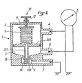
- FIGS. 1 to 3 show three embodiments respectively provided with a membrane, a piston and a bellows metallic.
- Figures 1 to 3 show an apparatus formed by a body 1 whose interior is separated by means sensitive to pressures 100, 200, 300 so as to form a chamber HP 2 and a chamber BP3.
- the HP chamber 2 has an inlet orifice 6 connected by a pipe 7 to the HP line. This HP chamber is also provided with an outlet 8 connected to the sensor 5.
- a spring 9 which is wedged between the pressure-sensitive means 100, 200, 300 and a device 10 for adjusting the compression of said spring.
- the adjustment device is formed by a plate 11 secured to a screw 12 which passes through a conjugate thread of the upper part of the body 1.
- the body 1 forms a shoulder 13 which constitutes a seat for a first valve 101, 201, 301 disposed upstream of said orifice and urged by a spring 14 wedged in the pipe 7.
- the pressure-sensitive means is a membrane 100, the periphery of which is clamped between two constituent parts of the body 1.
- the center of the membrane 100 is provided with an orifice while a tubular pusher 102 is fixed to said membrane coaxially with its central orifice and extends into the HP chamber 2.
- the pusher 102 is for example formed by a tube provided with a collar 103 on which the membrane rests while a washer 104, for example screwed to the end of the pusher, fixes the assembly.
- the spring 9 is applied to the washer 104 and therefore exerts its effect on the membrane 100.
- the end of the tubular pusher 102 rests, in the position shown, on the first valve 101.
- FIG. 2 presents a device very similar to that of FIG. 1 with the exception of the pressure-sensitive means which is constituted here by a piston 200.
- the piston 200 is pierced in its center like the membrane 100, while this central orifice is extended by a tubular plunger 202.
- the piston 200 is biased by the spring 9 and can slide in leaktight manner in the body 1 between the inlet 4 of the BP chamber and the outlet 8 of the HP chamber.
- FIG. 3 has a slightly different structure in terms of the pressure-sensitive means and the shutter valves.
- the device of FIG. 3 is provided with a metal bellows 300 fixed at its periphery, like the membrane 100, in the body 1.
- This bellows extends in the BP chamber and has a central orifice formed at its top which, like shown in the figure, is reinforced.
- the central opening of the bellows 300 is closable by a second valve 305.
- the second valve 305 is provided with an extension 306 secured at its other end to the valve 301.
- this device is provided with a guide 307 fixed to the body 1 to guide the extension 306.
- FIGS. 1 and 2 can perfectly be equipped with the means 301, 305, 306 and 307 of FIG. 3 in place of the means respectively 101, 102, 103 and 104 or 201 and 202.
- the apparatus of FIG. 3 can be equipped with means 101 to 104 in place of means 301, 305, 306 and 307.
- the pressure-sensitive means can be either a membrane 100, a piston 200 or a bellows 300 and the sealing means can be either constituted by a tubular plunger 102, 202, combined with a first valve 101, 201 or by the two first and second valve 301 and 305 connected by an extension 306.
- the spring 9 is calibrated by the adjusting means 10 to exert a back pressure substantially equal to the maximum difference between the HP and the BP admissible by the sensor 5, the spring 14 here being negligible.
- the first valve 101, 201, 301 indirectly biased by the spring 9 remains open and the sensor 5 normally receives the pressures prevailing in the lines HP and BP.
- the pressure-sensitive means deforms (membrane 100, bellows 300) or moves (piston 200) towards the BP chamber 3, so that the first valve 101, 201, 301 biased by the spring 14 closes the inlet orifice 6 of the HP chamber 2.
- the closure of the first valve 101,201,301 is therefore obtained by the pressure exerted on the means sensitive to the pressures and which causes the lifting of the pusher 102, 202 or the extension 306 and therefore that of the first valve.
- first valve 101, 201, 301 has a small surface on which a pressure is exerted which tends to close it and which will be discussed below.
- the pusher 102, 202 (FIG. 1 and 2) or the second valve 305 (FIG. 3) closes the orifice of the pressure-sensitive means by virtue of the spring 14 .
- the pressure-sensitive means continues to deform (100, 300) or to move (200), which results in the separation of the tubular pusher 102, 202 and the first valve 101,201 or respectively the opening of the second valve 305, so that the chambers HP and BP communicate, which tends to balance the pressures, thus protecting the sensor 5.
- the passage of the fluid from the HP chamber into the BP chamber leads to a reduction in the pressure difference and causes a reverse movement to that already described, of the pressure-sensitive means. This movement causes the communication between the chambers to be closed by applying the pusher 102, 202 to the first valve 101, 201 or respectively closing the second valve 305.
- the senor 5 is again in direct communication with the HP and BP lines until a new excessively large pressure difference comes again to cause the abovementioned operations.
- the structure of the devices shown creates a small hysteresis between the closing of the first valve 101, 201, 301 and the communication between the HP and BP chambers.
- said first valve closes by the forces exerted by the fluids on the pressure-sensitive means and on the first valve itself, that is to say for a pressure difference slightly less than the back pressure exerted by the spring 9 while the communication of the chambers occurs for a pressure difference equal to said back pressure.
- the embodiment will generally be chosen according to the pressures and fluids encountered, the embodiments of FIGS. 2 and 3 being more particularly intended for high pressures and aggressive fluids.
Landscapes
- Physics & Mathematics (AREA)
- General Physics & Mathematics (AREA)
- Measuring Fluid Pressure (AREA)
Priority Applications (1)
| Application Number | Priority Date | Filing Date | Title |
|---|---|---|---|
| AT81401621T ATE14933T1 (de) | 1981-01-27 | 1981-10-15 | Schutzvorrichtung fuer differenzdruckaufnehmer gegen das ueberschreiten eines gegebenen maximalen differentialen druckes. |
Applications Claiming Priority (2)
| Application Number | Priority Date | Filing Date | Title |
|---|---|---|---|
| FR8101436 | 1981-01-27 | ||
| FR8101436A FR2498755A1 (fr) | 1981-01-27 | 1981-01-27 | Appareil de protection pour capteurs de pressions differentielles contre le depassement d'une pression differentielle maximale donnee |
Publications (2)
| Publication Number | Publication Date |
|---|---|
| EP0056913A1 EP0056913A1 (fr) | 1982-08-04 |
| EP0056913B1 true EP0056913B1 (fr) | 1985-08-14 |
Family
ID=9254529
Family Applications (1)
| Application Number | Title | Priority Date | Filing Date |
|---|---|---|---|
| EP81401621A Expired EP0056913B1 (fr) | 1981-01-27 | 1981-10-15 | Appareil de protection pour capteurs de pressions différentielles contre le dépassement d'une pression différentielle maximale donnée |
Country Status (5)
| Country | Link |
|---|---|
| US (1) | US4461180A (enExample) |
| EP (1) | EP0056913B1 (enExample) |
| AT (1) | ATE14933T1 (enExample) |
| DE (1) | DE3171824D1 (enExample) |
| FR (1) | FR2498755A1 (enExample) |
Families Citing this family (18)
| Publication number | Priority date | Publication date | Assignee | Title |
|---|---|---|---|---|
| FR2498755A1 (fr) * | 1981-01-27 | 1982-07-30 | Ams Sa | Appareil de protection pour capteurs de pressions differentielles contre le depassement d'une pression differentielle maximale donnee |
| US4449412A (en) * | 1982-09-28 | 1984-05-22 | Draft Systems, Inc. | Safety pressure gage |
| US4576054A (en) * | 1983-07-12 | 1986-03-18 | Lalin Hill S | Dual mode gas sampler and pneumatic flow control system |
| US4566807A (en) * | 1984-02-09 | 1986-01-28 | The Dow Chemical Company | Apparatus and method for accurately measuring temperatures and temperature differences |
| US5337612A (en) * | 1992-06-08 | 1994-08-16 | Quartzdyne, Inc. | Apparatus for pressure transducer isolation |
| CH690935A5 (de) * | 1996-02-02 | 2001-02-28 | Electrical Eng Co Ltd | Messwertaufnehmer für Druck. |
| US7363811B2 (en) * | 2005-04-07 | 2008-04-29 | Endress + Hauser Flowtec Ag | Measurement pickup |
| FR2901880B1 (fr) * | 2006-06-01 | 2008-11-07 | Equip Aero Tech Soc Par Action | Detecteur de rapport de pressions absolues |
| DE102008057991B4 (de) * | 2008-11-19 | 2013-06-13 | B/E Aerospace Systems Gmbh | Cockpitsauerstoffversorgungsvorrichtung |
| CN101957249B (zh) * | 2010-09-27 | 2012-03-07 | 浙江大学 | 一种差压测量装置及其过载保护装置 |
| US8671766B2 (en) * | 2011-05-19 | 2014-03-18 | Infineon Technologies Ag | Integrated pressure sensor seal |
| CN104736984B (zh) * | 2012-11-30 | 2017-09-08 | 富士电机株式会社 | 压力传感器装置及压力传感器装置的制造方法 |
| WO2015036374A2 (en) | 2013-09-12 | 2015-03-19 | Akzo Nobel Chemicals International B.V. | Acidic fertilizer compositions containing a metal complex of glutamic acid n,n-diacetic acid or iminodisuccinic acid |
| US9759625B2 (en) * | 2015-09-18 | 2017-09-12 | Tecsis Gmbh | Differential pressure transducer assembly with overload protection |
| CN105890973A (zh) * | 2016-04-01 | 2016-08-24 | 烟台正海合泰科技股份有限公司 | 拉力试验机上的弹性保护装置 |
| NL2016557B1 (en) * | 2016-04-06 | 2017-10-17 | Fugro Eng B V | Pressure measurement device. |
| EP3246253B1 (en) * | 2016-05-19 | 2018-11-28 | Airbus Operations GmbH | Differential pressure sensor system, aircraft equipped with a differential pressure sensor system and method for operating a differential pressure sensor system |
| CN110480459B (zh) * | 2019-08-23 | 2021-04-16 | 安徽博晟亿电力科技有限公司 | 一种生铁打磨设备的减震组件 |
Family Cites Families (15)
| Publication number | Priority date | Publication date | Assignee | Title |
|---|---|---|---|---|
| CA649344A (en) * | 1962-09-25 | Lester D. Savage, Jr. | Device for the protection of pressure measuring elements | |
| US2627183A (en) * | 1948-06-17 | 1953-02-03 | Gen Precision Lab Inc | Pressure translator |
| US2558534A (en) * | 1950-06-19 | 1951-06-26 | Gen Electric | Over-pressure protective device |
| FR1042197A (fr) * | 1950-09-16 | 1953-10-29 | Dunlop Rubber Co | Relais hydraulique |
| US2981110A (en) * | 1955-04-28 | 1961-04-25 | Fenn Arthur George | Pressure fluid systems |
| US3290945A (en) * | 1961-08-21 | 1966-12-13 | Li Yao Tzu | Differential pressure responsive device |
| US3718048A (en) * | 1971-06-07 | 1973-02-27 | Kingmann White | Relief valves for differential pressure flow meters |
| US3712143A (en) * | 1971-12-21 | 1973-01-23 | Honeywell Inc | Differential pressure responsive apparatus |
| US3756085A (en) * | 1972-01-03 | 1973-09-04 | Bailey Meter Co | Differential pressure transmitter overrange protection |
| DE2556285A1 (de) * | 1975-12-13 | 1977-06-23 | Eckardt Ag | Differenzdruckanzeiger |
| GB1566703A (en) * | 1976-10-04 | 1980-05-08 | Kent Ltd G | Pressure sensing devices |
| SU620856A1 (ru) * | 1976-11-17 | 1978-08-25 | Войсковая Часть 44526 | Предохранительное устройство дл датчика давлени |
| US4135407A (en) * | 1978-04-03 | 1979-01-23 | The Foxboro Company | Method and apparatus for overrange protection of the transducer in a differential pressure transmitter |
| FR2445521A1 (fr) * | 1978-12-29 | 1980-07-25 | Sibe | Dispositif de protection pour manometre differentiel |
| FR2498755A1 (fr) * | 1981-01-27 | 1982-07-30 | Ams Sa | Appareil de protection pour capteurs de pressions differentielles contre le depassement d'une pression differentielle maximale donnee |
-
1981
- 1981-01-27 FR FR8101436A patent/FR2498755A1/fr active Granted
- 1981-10-15 AT AT81401621T patent/ATE14933T1/de not_active IP Right Cessation
- 1981-10-15 DE DE8181401621T patent/DE3171824D1/de not_active Expired
- 1981-10-15 EP EP81401621A patent/EP0056913B1/fr not_active Expired
-
1982
- 1982-01-26 US US06/342,731 patent/US4461180A/en not_active Expired - Fee Related
Also Published As
| Publication number | Publication date |
|---|---|
| FR2498755B1 (enExample) | 1983-11-10 |
| US4461180A (en) | 1984-07-24 |
| ATE14933T1 (de) | 1985-08-15 |
| DE3171824D1 (en) | 1985-09-19 |
| FR2498755A1 (fr) | 1982-07-30 |
| EP0056913A1 (fr) | 1982-08-04 |
Similar Documents
| Publication | Publication Date | Title |
|---|---|---|
| EP0056913B1 (fr) | Appareil de protection pour capteurs de pressions différentielles contre le dépassement d'une pression différentielle maximale donnée | |
| EP0467769B1 (fr) | Dispositif adaptateur-détendeur de distribution de gaz pour conteneurs de gaz à haute pression | |
| EP0091843B1 (fr) | Embout pour appareil respiratoire, pour le raccordement du masque à une bouteille de gaz respiratoire | |
| BE529033A (fr) | Appareil régulateur de la pression d'écoulement d'un fluide dans un conduit avec dispositif pilote | |
| WO2002084275A1 (fr) | Dispositif de protection du lit chromatographique dans les colonnes chromatographique a compression axiale dynamique | |
| FR2600744A1 (fr) | Robinet d'arret et de commande d'ecoulement | |
| EP1931959B1 (fr) | Vanne de commande d'ecoulement de fluide | |
| FR2792387A1 (fr) | Raccord a soupapes pour un recipient sous pression | |
| EP0328472B1 (fr) | Raccord-démarreur pour la mise en pression progressive d'installations pneumatiques | |
| EP0214023B1 (fr) | Dispositif limiteur de débit pour robinets de bouteilles à gaz comprimé ou liquéfié sous pression | |
| FR2533697A1 (fr) | Dispositif combine constituant un manometre et un detendeur de pression, et manometre de securite | |
| FR2731071A1 (fr) | Indicateur de pression differentielle | |
| CA1211678A (fr) | Soupape de securite pilotee | |
| FR2786242A1 (fr) | Soupape d'arret de basse et haute pression | |
| EP1936255A1 (fr) | Robinet pour réservoir de gaz sous pression et réservoir comportant un tel robinet | |
| FR2499665A1 (fr) | Clapet anti-retour pilote hydrauliquement pour systemes hydrauliques a haute pression, en particulier pour systemes de soutenement hydrauliques d'exploitations minieres souterraines | |
| FR2502729A1 (fr) | Vanne en tout ou rien a declenchement pyrotechnique | |
| WO1980002874A1 (fr) | Dispositif de mesure et de controle de debits gazeux | |
| FR2672993A1 (fr) | Dispositif d'essai de compression triaxiale d'eprouvettes. | |
| WO1994005940A1 (fr) | Vanne du type a siege cylindrique, a siege conique ou a tiroir | |
| FR3056677A1 (fr) | Robinet pour fluide sous pression | |
| FR2654794A1 (fr) | Detendeur neutralisable. | |
| EP0128787B1 (fr) | Pompe radiale monocylindrique ou multicylindrique | |
| EP3760912B1 (fr) | Bouteille de fluide sous pression | |
| WO1982000197A1 (fr) | Dispositif de mesure et de controle de debits gazeux |
Legal Events
| Date | Code | Title | Description |
|---|---|---|---|
| PUAI | Public reference made under article 153(3) epc to a published international application that has entered the european phase |
Free format text: ORIGINAL CODE: 0009012 |
|
| AK | Designated contracting states |
Designated state(s): AT BE CH DE GB IT LU NL SE |
|
| 17P | Request for examination filed |
Effective date: 19820924 |
|
| ITF | It: translation for a ep patent filed | ||
| GRAA | (expected) grant |
Free format text: ORIGINAL CODE: 0009210 |
|
| AK | Designated contracting states |
Designated state(s): AT BE CH DE GB IT LI LU NL SE |
|
| PG25 | Lapsed in a contracting state [announced via postgrant information from national office to epo] |
Ref country code: AT Effective date: 19850814 |
|
| REF | Corresponds to: |
Ref document number: 14933 Country of ref document: AT Date of ref document: 19850815 Kind code of ref document: T |
|
| REF | Corresponds to: |
Ref document number: 3171824 Country of ref document: DE Date of ref document: 19850919 |
|
| PG25 | Lapsed in a contracting state [announced via postgrant information from national office to epo] |
Ref country code: LU Free format text: LAPSE BECAUSE OF NON-PAYMENT OF DUE FEES Effective date: 19851031 Ref country code: LI Effective date: 19851031 Ref country code: CH Effective date: 19851031 Ref country code: BE Effective date: 19851031 |
|
| BERE | Be: lapsed |
Owner name: APPAREILLAGES ET MATERIELS DE SERVITUDES AMS S.A Effective date: 19851031 |
|
| REG | Reference to a national code |
Ref country code: CH Ref legal event code: PL |
|
| PLBE | No opposition filed within time limit |
Free format text: ORIGINAL CODE: 0009261 |
|
| STAA | Information on the status of an ep patent application or granted ep patent |
Free format text: STATUS: NO OPPOSITION FILED WITHIN TIME LIMIT |
|
| 26N | No opposition filed | ||
| ITTA | It: last paid annual fee | ||
| PGFP | Annual fee paid to national office [announced via postgrant information from national office to epo] |
Ref country code: NL Payment date: 19891031 Year of fee payment: 9 |
|
| PGFP | Annual fee paid to national office [announced via postgrant information from national office to epo] |
Ref country code: DE Payment date: 19891228 Year of fee payment: 9 |
|
| PGFP | Annual fee paid to national office [announced via postgrant information from national office to epo] |
Ref country code: GB Payment date: 19900905 Year of fee payment: 10 |
|
| PGFP | Annual fee paid to national office [announced via postgrant information from national office to epo] |
Ref country code: SE Payment date: 19901022 Year of fee payment: 10 |
|
| PG25 | Lapsed in a contracting state [announced via postgrant information from national office to epo] |
Ref country code: NL Effective date: 19910501 |
|
| NLV4 | Nl: lapsed or anulled due to non-payment of the annual fee | ||
| PG25 | Lapsed in a contracting state [announced via postgrant information from national office to epo] |
Ref country code: DE Effective date: 19910702 |
|
| PG25 | Lapsed in a contracting state [announced via postgrant information from national office to epo] |
Ref country code: GB Effective date: 19911015 |
|
| PG25 | Lapsed in a contracting state [announced via postgrant information from national office to epo] |
Ref country code: SE Effective date: 19911016 |
|
| GBPC | Gb: european patent ceased through non-payment of renewal fee | ||
| EUG | Se: european patent has lapsed |
Ref document number: 81401621.8 Effective date: 19920510 |