EP0056757B1 - Gasbrenner, Verfahren zur Herstellung des Brenners und Anwendung eines solchen Brenners bei einem Kessel - Google Patents
Gasbrenner, Verfahren zur Herstellung des Brenners und Anwendung eines solchen Brenners bei einem Kessel Download PDFInfo
- Publication number
- EP0056757B1 EP0056757B1 EP82400053A EP82400053A EP0056757B1 EP 0056757 B1 EP0056757 B1 EP 0056757B1 EP 82400053 A EP82400053 A EP 82400053A EP 82400053 A EP82400053 A EP 82400053A EP 0056757 B1 EP0056757 B1 EP 0056757B1
- Authority
- EP
- European Patent Office
- Prior art keywords
- burner
- mixture
- gas
- proportion
- weight
- Prior art date
- Legal status (The legal status is an assumption and is not a legal conclusion. Google has not performed a legal analysis and makes no representation as to the accuracy of the status listed.)
- Expired
Links
- 238000004519 manufacturing process Methods 0.000 title claims description 10
- 238000000034 method Methods 0.000 title claims description 5
- 239000000203 mixture Substances 0.000 claims abstract description 31
- 239000000919 ceramic Substances 0.000 claims abstract description 29
- 239000007789 gas Substances 0.000 claims abstract description 25
- XLYOFNOQVPJJNP-UHFFFAOYSA-N water Substances O XLYOFNOQVPJJNP-UHFFFAOYSA-N 0.000 claims abstract description 16
- 239000011230 binding agent Substances 0.000 claims abstract description 12
- 239000011148 porous material Substances 0.000 claims abstract description 11
- PNEYBMLMFCGWSK-UHFFFAOYSA-N aluminium oxide Inorganic materials [O-2].[O-2].[O-2].[Al+3].[Al+3] PNEYBMLMFCGWSK-UHFFFAOYSA-N 0.000 claims abstract description 8
- 239000000567 combustion gas Substances 0.000 claims abstract description 6
- FHVDTGUDJYJELY-UHFFFAOYSA-N 6-{[2-carboxy-4,5-dihydroxy-6-(phosphanyloxy)oxan-3-yl]oxy}-4,5-dihydroxy-3-phosphanyloxane-2-carboxylic acid Chemical compound O1C(C(O)=O)C(P)C(O)C(O)C1OC1C(C(O)=O)OC(OP)C(O)C1O FHVDTGUDJYJELY-UHFFFAOYSA-N 0.000 claims abstract description 5
- 229920001353 Dextrin Polymers 0.000 claims abstract description 5
- 229940072056 alginate Drugs 0.000 claims abstract description 5
- 235000010443 alginic acid Nutrition 0.000 claims abstract description 5
- 229920000615 alginic acid Polymers 0.000 claims abstract description 5
- 239000000440 bentonite Substances 0.000 claims abstract description 5
- 229910000278 bentonite Inorganic materials 0.000 claims abstract description 5
- SVPXDRXYRYOSEX-UHFFFAOYSA-N bentoquatam Chemical compound O.O=[Si]=O.O=[Al]O[Al]=O SVPXDRXYRYOSEX-UHFFFAOYSA-N 0.000 claims abstract description 5
- 239000004927 clay Substances 0.000 claims abstract description 5
- KZHJGOXRZJKJNY-UHFFFAOYSA-N dioxosilane;oxo(oxoalumanyloxy)alumane Chemical compound O=[Si]=O.O=[Si]=O.O=[Al]O[Al]=O.O=[Al]O[Al]=O.O=[Al]O[Al]=O KZHJGOXRZJKJNY-UHFFFAOYSA-N 0.000 claims abstract description 5
- 229910052863 mullite Inorganic materials 0.000 claims abstract description 5
- 229910052851 sillimanite Inorganic materials 0.000 claims abstract description 5
- -1 corindon Inorganic materials 0.000 claims abstract 3
- FYGDTMLNYKFZSV-MRCIVHHJSA-N dextrin Chemical compound O[C@@H]1[C@@H](O)[C@H](O)[C@@H](CO)OC1O[C@@H]1[C@@H](CO)OC(O[C@@H]2[C@H](O[C@H](O)[C@H](O)[C@H]2O)CO)[C@H](O)[C@H]1O FYGDTMLNYKFZSV-MRCIVHHJSA-N 0.000 claims abstract 3
- 230000007717 exclusion Effects 0.000 claims abstract 2
- 239000002923 metal particle Substances 0.000 claims abstract 2
- 238000002485 combustion reaction Methods 0.000 claims description 9
- 239000012530 fluid Substances 0.000 claims description 3
- 239000002184 metal Substances 0.000 description 14
- 229910052751 metal Inorganic materials 0.000 description 14
- 239000002245 particle Substances 0.000 description 5
- 230000006866 deterioration Effects 0.000 description 4
- 238000010438 heat treatment Methods 0.000 description 4
- 229910001220 stainless steel Inorganic materials 0.000 description 4
- 239000010935 stainless steel Substances 0.000 description 4
- 229910052593 corundum Inorganic materials 0.000 description 3
- 239000010431 corundum Substances 0.000 description 3
- 238000005336 cracking Methods 0.000 description 3
- 238000000465 moulding Methods 0.000 description 3
- 230000002093 peripheral effect Effects 0.000 description 3
- 239000011819 refractory material Substances 0.000 description 3
- CURLTUGMZLYLDI-UHFFFAOYSA-N Carbon dioxide Chemical compound O=C=O CURLTUGMZLYLDI-UHFFFAOYSA-N 0.000 description 2
- 239000004375 Dextrin Substances 0.000 description 2
- 229920002472 Starch Polymers 0.000 description 2
- 238000006243 chemical reaction Methods 0.000 description 2
- 230000006378 damage Effects 0.000 description 2
- 238000013461 design Methods 0.000 description 2
- 235000019425 dextrin Nutrition 0.000 description 2
- 238000000605 extraction Methods 0.000 description 2
- 238000010304 firing Methods 0.000 description 2
- 239000008187 granular material Substances 0.000 description 2
- 239000013529 heat transfer fluid Substances 0.000 description 2
- 239000000463 material Substances 0.000 description 2
- 239000000843 powder Substances 0.000 description 2
- 230000005855 radiation Effects 0.000 description 2
- 238000005245 sintering Methods 0.000 description 2
- 235000019698 starch Nutrition 0.000 description 2
- 239000008107 starch Substances 0.000 description 2
- 238000012360 testing method Methods 0.000 description 2
- 208000037656 Respiratory Sounds Diseases 0.000 description 1
- 239000000378 calcium silicate Substances 0.000 description 1
- 229910052918 calcium silicate Inorganic materials 0.000 description 1
- OYACROKNLOSFPA-UHFFFAOYSA-N calcium;dioxido(oxo)silane Chemical compound [Ca+2].[O-][Si]([O-])=O OYACROKNLOSFPA-UHFFFAOYSA-N 0.000 description 1
- 229910002092 carbon dioxide Inorganic materials 0.000 description 1
- 239000001569 carbon dioxide Substances 0.000 description 1
- 230000000295 complement effect Effects 0.000 description 1
- 238000001816 cooling Methods 0.000 description 1
- 238000005553 drilling Methods 0.000 description 1
- 238000001035 drying Methods 0.000 description 1
- 238000011156 evaluation Methods 0.000 description 1
- 230000002349 favourable effect Effects 0.000 description 1
- 239000000446 fuel Substances 0.000 description 1
- 230000004927 fusion Effects 0.000 description 1
- 239000008246 gaseous mixture Substances 0.000 description 1
- 238000005469 granulation Methods 0.000 description 1
- 230000003179 granulation Effects 0.000 description 1
- 238000005470 impregnation Methods 0.000 description 1
- 238000011065 in-situ storage Methods 0.000 description 1
- 238000002347 injection Methods 0.000 description 1
- 239000007924 injection Substances 0.000 description 1
- 238000009434 installation Methods 0.000 description 1
- 238000003754 machining Methods 0.000 description 1
- 238000012423 maintenance Methods 0.000 description 1
- 239000007769 metal material Substances 0.000 description 1
- 239000013528 metallic particle Substances 0.000 description 1
- 238000002156 mixing Methods 0.000 description 1
- 238000012544 monitoring process Methods 0.000 description 1
- 238000013021 overheating Methods 0.000 description 1
- 230000001590 oxidative effect Effects 0.000 description 1
- 238000007789 sealing Methods 0.000 description 1
- 230000008646 thermal stress Effects 0.000 description 1
Images
Classifications
-
- C—CHEMISTRY; METALLURGY
- C04—CEMENTS; CONCRETE; ARTIFICIAL STONE; CERAMICS; REFRACTORIES
- C04B—LIME, MAGNESIA; SLAG; CEMENTS; COMPOSITIONS THEREOF, e.g. MORTARS, CONCRETE OR LIKE BUILDING MATERIALS; ARTIFICIAL STONE; CERAMICS; REFRACTORIES; TREATMENT OF NATURAL STONE
- C04B35/00—Shaped ceramic products characterised by their composition; Ceramics compositions; Processing powders of inorganic compounds preparatory to the manufacturing of ceramic products
- C04B35/01—Shaped ceramic products characterised by their composition; Ceramics compositions; Processing powders of inorganic compounds preparatory to the manufacturing of ceramic products based on oxide ceramics
- C04B35/10—Shaped ceramic products characterised by their composition; Ceramics compositions; Processing powders of inorganic compounds preparatory to the manufacturing of ceramic products based on oxide ceramics based on aluminium oxide
-
- F—MECHANICAL ENGINEERING; LIGHTING; HEATING; WEAPONS; BLASTING
- F23—COMBUSTION APPARATUS; COMBUSTION PROCESSES
- F23D—BURNERS
- F23D14/00—Burners for combustion of a gas, e.g. of a gas stored under pressure as a liquid
- F23D14/12—Radiant burners
- F23D14/16—Radiant burners using permeable blocks
-
- F—MECHANICAL ENGINEERING; LIGHTING; HEATING; WEAPONS; BLASTING
- F24—HEATING; RANGES; VENTILATING
- F24H—FLUID HEATERS, e.g. WATER OR AIR HEATERS, HAVING HEAT-GENERATING MEANS, e.g. HEAT PUMPS, IN GENERAL
- F24H1/00—Water heaters, e.g. boilers, continuous-flow heaters or water-storage heaters
- F24H1/22—Water heaters other than continuous-flow or water-storage heaters, e.g. water heaters for central heating
- F24H1/24—Water heaters other than continuous-flow or water-storage heaters, e.g. water heaters for central heating with water mantle surrounding the combustion chamber or chambers
Definitions
- the present invention relates to a gas burner of a new design and a boiler using such a burner.
- Known gas burners are practically of two types: on the one hand, metal multi-hole or slot burners used for example in gas stoves, or metal multi-hole or slot burners used in gas boilers atmospheric, radiators, water heaters, etc ... and, on the other hand, ceramic burners pierced with holes by machining, molding, or injection.
- Metal burners of the first type have the disadvantage of requiring, for their proper functioning, not only primary air, but also complementary and essential secondary air, that is to say air mixing gas at the outlet of the burner slots and holes.
- this secondary air is practically not dosable and controllable, it can only cause the output of the burner to drop. It would be unthinkable to want to increase the efficiency of these burners by eliminating secondary air, without taking enormous precautions aimed at avoiding at all costs an excess of primary air which would cause the flame to catch on the wall of the burner and therefore overheating thereof beyond tolerable limits and its rapid destruction.
- said holes have too low a pressure drop to allow good attachment of the flame in total primary air and, on the other hand, the production of the holes is a delicate operation which significantly increases the price. of the finished product.
- Patent FR-A-2 126 742 certainly discloses a porous ceramic burner formed of a permeable core constituted by particle size fractions of a refractory material, surrounded by a lateral envelope of refractory material, the core and the casing being sintered, but this burner, which has two basic elements, has a complicated structure, is difficult to manufacture and is therefore relatively expensive.
- the patent FR-A-2 380 999 describes a process for manufacturing alumina products with high porosity, consisting in using a very fine powder of alumina which is agglomerated into granules and in molding the granules before they are sinter. Such a manufacturing process has the same drawbacks as those of the burner according to patent FR-A-2 457 267 and further requires the use of fine alumina powder which is a relatively expensive product.
- Patent FR-A-2 236 809 relates to an artificial body comprising a hard material, such as corundum and a binder with calcium silicate.
- a hard material such as corundum
- a binder with calcium silicate The impregnation of hard materials by temporary binders is difficult to obtain and calls for complicated ovens, fusions and mixtures, as well as a granulation operation.
- gas boilers are known in which combustion is carried out by primary air exclusively, but which use perforated refractory stainless steel burners and equipped with extractors suitable for entraining the quantity of primary air necessary for combustion of gas.
- patent FR-A-1 056 484 describes a heating device constituted by a burner made of porous metallic material through which seeps a mixture of combustible gas and combustion air which is ignited on the external surface of the burner .
- the gaseous fuel can be mixed with primary air, which means that the oxidizing gas is necessarily secondary air.
- Such a burner, which uses secondary air will therefore have a low efficiency, as explained above.
- the operation of such a burner with only primary air is completely excluded because because of its composition (which involves metallic particles) and its manufacturing process (by molding and heating to the sintering temperature or the burner may turn red and be destroyed. In addition, catching the flame may cause cracking in the long run on heating and cooling.
- this burner which is produced by the assembly of three separate parts, is of complicated structure and is therefore expensive.
- the patent US-A-1 731 053 describes a burner made of porous refractory material, which, to avoid the risks of cracking caused by thermal stresses and which one meets in ceramic burners, comprises crossed trenches. In addition to the fact that such grooves complicate the shape of the burner, it emerges from this patent that the face of the burner on which the flame is attached is exposed to the atmosphere, that is to say to the secondary air. The efficiency of such a burner is therefore low.
- the present invention aims to remedy all these drawbacks by proposing a gas burner made of porous ceramic, which is simple to to manufacture and which can possibly function only with primary air, therefore with an excellent yield, while supporting the relatively high temperatures which are manifested on its surface.
- the gas burner according to the invention is produced in a single piece from a mixture of alumina, such as corundum, sillimanite or mullite with a particle size between 0.2 and 2.5 mm, of binder final, such as clay or bentonite in a proportion of 10 to 40% by weight, of the mixture of temporary binders of the starch, dextrin or alginate type in a proportion of 1 to 10% by weight of the mixture, and of water in a proportion of 1 to 10% by weight of the mixture, the pores of said body being distributed over its entire surface and determining a pressure drop of the order of 1 to 20 mm of water column for the mixture of combustion gases and primary air passing through them, the outlet face of the burner on which the flame is formed being exposed to an atmosphere devoid of secondary air.
- binder final such as clay or bentonite
- binder final such as clay or bentonite
- binder final such as clay or bentonite
- the ceramic composition is prepared from a mixture of a variety of alumina, such as corundum, sillimanite, or mullite, etc., having an average particle size of between 0.2 and 2.5 mm, d '' a definitive binder such as clay or bentonite in a proportion of 10 to 40% by weight, of temporary binders of the starch, dextrin or alginate type in a proportion of 1 to 10% by weight, and from 1 to 10% of water.
- alumina such as corundum, sillimanite, or mullite, etc.
- the mixture is sieved through a sieve of 1 to 2.5 mm in mesh size, then isostatically pressed, preferably in suitable molds in the form of hollow bodies open at one end or of plates, etc.
- the body may be advantageously in the form of a test tube or crucible.
- the drying and firing are then carried out in a ceramic oven at a temperature between 1000 and 1600 ° C. depending on the composition of the mixture. A ceramic body with a porous texture is thus obtained, the pores of which are distributed over the entire surface of the body.
- the present invention also relates to a boiler which uses as a burner, the porous ceramic burner described above.
- the boiler comprises two concentric envelopes defining between them a sealed annular chamber in which is maintained a circulation of heat-transfer fluid, such as water, the burner being mounted inside the internal shell of the boiler, with its opening facing the side of a gas injector and sealingly adapting to the inlet opening of the internal shell.
- the inner chamber of the internal envelope can either be placed under vacuum, the vacuum being exerted from downstream of the burner, or operate under pressure, the pressure being exerted on the side of the gas inlet.
- the burner according to the invention can have its surface area brought to temperatures of the order of 800 ° C., that is to say to bright red, without risk of deterioration or reduction of the service life. Such a temperature cannot be reached either with the metal burners without certain deterioration, or with the multi-hole ceramic burners because the pressure drop is too low.
- the burner and the boiler according to the invention operate exclusively on total primary air since the enclosure in which the burner is mounted is airtight with respect to the secondary air and can be placed under vacuum. It follows that the burner is not cooled as is the case for burners operating with secondary air and that the efficiency of the burner is therefore considerably higher than that of said secondary air burners.
- the ceramic burner of the same design would allow atmospheric use proper (c (i.e. without mechanical extraction and with secondary air) adjustable according to the quantity of gas. It could even operate with an excess of primary air, which is completely excluded with a metal burner. Such a low pressure drop burner could operate with primary air and peripheral secondary air assuming higher yields than stainless steel burners.
- the service life of the primary and secondary air stainless steel burners is in fact significantly shortened if the flame is well attached, that is to say in the case of very good yields, while in the ceramic burner of the invention, the flame is by definition well attached and despite this it does not threaten the longevity of the burner.
- All gas burners of the stainless steel or more generally metal type such as those used in water heaters, bath heaters, radiators, wall or floor boilers have, under the best conditions, combustion efficiency , measured in carbon dioxide content, of the order of 6 to 9%.
- combustion efficiency measured in carbon dioxide content
- the use of ceramic burners according to the invention makes it possible to achieve yields which can exceed by 20% or even more these abovementioned yields which can be obtained with extraction of primary air and without secondary air, and around 15% or more when used as an atmospheric burner with induced primary air and ambient secondary air.
- the gain in calories by radiation of the ceramic brought to red is not taken into account.
- the metal burners on the contrary, emit practically no energy by radiation, unless they are brought to red, that is to say just before their destruction.
- combustion is improving, in the case of the burner and of the boiler of the invention, as the temperature of the porous ceramic element rises to bright red.
- the centering and positioning of the injector, the drilling diameter of the latter, the shape, the position and the size of the Venturi are critical parameters, while in the burner in ceramic according to the invention, these parameters can be chosen less rigorously.
- porous ceramic burner according to the invention successfully withstands such possible constraints.
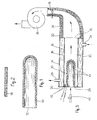
- the burner 10 shown in FIG. 1 is made of porous ceramic, the composition and the method of manufacture of which have been specified previously.
- the burner is in the form of a test tube or crucible open at one end 12 and closed at the other end. It has a multitude of pores distributed over its entire surface and which constitute passageways for the gaseous fluid (air + combustion gas) admitted inside the burner.
- the pores are dimensioned so as to cause a pressure drop of the combustion gas-primary air mixture of the order of 1 to 20 mm of water column.
- the burner 13 shown in FIG. 2 is also made of ceramic by the same process as the burner 10. It is in the form of a plate and its pores are dimensioned to allow the passage of the gaseous fluid through the plate, with a pressure drop. from 1 to 20 mm of water column.
- the boiler according to the invention comprises two concentric envelopes 14, 16 of metal, defining between them an annular chamber 18 closed at its inlet and outlet ends by end walls 20, 22.
- the chamber 18 is filled with a heat transfer fluid, such as water, circulated by suitable means not shown, through an inlet pipe 24 and an outlet pipe 26.
- a burner 10 similar to that of FIG. 1.
- the burner is adapted with sealing, by its open end, in an orifice 28 drilled in the wall 20 which closes the inlet end of the chamber 30 defined inside the internal envelope 16.
- the outlet end 32 of the latter is open and is connected to a suction pipe 34 equipped with a fan 36 and a valve 38 for metering the flow rate of the primary air and gas mixture drawn through the pores of the burner.
- the combustion gas is blown inside the burner by an injector 40 mounted substantially in the axis of the burner.
- Electrodes 42 opening into the interior of the chamber 30 in the vicinity of the external surface of the burner make it possible, when they are energized, to ignite the gaseous mixture exiting through the pores of the burner. A multitude of small flames 44 is thus obtained uniformly distributed and well hung on the surface of the burner.
- the boiler and the burner only operate with primary air, in the absence of peripheral secondary air.
- the burner can therefore be brought to temperatures of the order of 800 ° C. without risk of deterioration.
- Significantly higher yields are thus obtained than with metal burners.
Landscapes
- Engineering & Computer Science (AREA)
- Chemical & Material Sciences (AREA)
- General Engineering & Computer Science (AREA)
- Combustion & Propulsion (AREA)
- Mechanical Engineering (AREA)
- Ceramic Engineering (AREA)
- Thermal Sciences (AREA)
- Physics & Mathematics (AREA)
- Manufacturing & Machinery (AREA)
- Materials Engineering (AREA)
- Structural Engineering (AREA)
- Organic Chemistry (AREA)
- Gas Burners (AREA)
- Spray-Type Burners (AREA)
Claims (8)
Priority Applications (1)
| Application Number | Priority Date | Filing Date | Title |
|---|---|---|---|
| AT82400053T ATE12979T1 (de) | 1981-01-15 | 1982-01-13 | Gasbrenner, verfahren zur herstellung des brenners und anwendung eines solchen brenners bei einem kessel. |
Applications Claiming Priority (2)
| Application Number | Priority Date | Filing Date | Title |
|---|---|---|---|
| FR8100653 | 1981-01-15 | ||
| FR8100653A FR2497923B1 (fr) | 1981-01-15 | 1981-01-15 | Bruleur a gaz, procede de fabrication dudit bruleur et chaudiere utilisant un tel bruleur |
Publications (3)
| Publication Number | Publication Date |
|---|---|
| EP0056757A2 EP0056757A2 (de) | 1982-07-28 |
| EP0056757A3 EP0056757A3 (en) | 1982-08-25 |
| EP0056757B1 true EP0056757B1 (de) | 1985-04-24 |
Family
ID=9254171
Family Applications (1)
| Application Number | Title | Priority Date | Filing Date |
|---|---|---|---|
| EP82400053A Expired EP0056757B1 (de) | 1981-01-15 | 1982-01-13 | Gasbrenner, Verfahren zur Herstellung des Brenners und Anwendung eines solchen Brenners bei einem Kessel |
Country Status (4)
| Country | Link |
|---|---|
| EP (1) | EP0056757B1 (de) |
| AT (1) | ATE12979T1 (de) |
| DE (1) | DE3263189D1 (de) |
| FR (1) | FR2497923B1 (de) |
Families Citing this family (4)
| Publication number | Priority date | Publication date | Assignee | Title |
|---|---|---|---|---|
| EP0168797A3 (de) * | 1984-07-14 | 1988-07-20 | Alligator Ventilfabrik GmbH | Vorrichtung zum Enteisen insbesondere von Windschutzscheiben |
| US4878837A (en) * | 1989-02-06 | 1989-11-07 | Carrier Corporation | Infrared burner |
| US5470222A (en) * | 1993-06-21 | 1995-11-28 | United Technologies Corporation | Heating unit with a high emissivity, porous ceramic flame holder |
| DE4324644A1 (de) * | 1993-07-22 | 1995-01-26 | Gossler Kg Oscar | Keramisches Verbrennungsträgerelement für Flächenbrenner und Verfahren zu seiner Herstellung |
Family Cites Families (9)
| Publication number | Priority date | Publication date | Assignee | Title |
|---|---|---|---|---|
| FR1056454A (de) * | 1954-02-26 | |||
| US1731053A (en) * | 1928-05-31 | 1929-10-08 | Doherty Res Co | Porous refractory diaphragm |
| GB1384873A (en) * | 1971-02-08 | 1975-02-26 | Shell Int Research | Method of manufacturing porous ceramic elements suitable for use in radiant heating appliances |
| FR2093226A6 (de) * | 1970-06-05 | 1972-01-28 | Gaz De France | |
| US3848661A (en) * | 1970-10-05 | 1974-11-19 | Fulton Boiler Works | Thermal fluid heater apparatus |
| FR2165120A5 (de) * | 1971-12-13 | 1973-08-03 | Laurencot Andre | |
| DE2333422A1 (de) * | 1972-07-03 | 1974-01-24 | Gullhoegens Bruk Ab | Hartstoff und verfahren zu seiner herstellung |
| IT1085777B (it) * | 1977-02-16 | 1985-05-28 | Montedison Spa | Procedimento per la produzione di manufatti a porosita' e permeabilita' controllate,costituiti da alluminia o da altri ossidi di elevata purezza |
| DE2920795A1 (de) * | 1979-05-22 | 1980-12-04 | Max Planck Gesellschaft | Hochfester und temperaturwechselbestaendiger keramikformkoerper, insbesondere aus mullit, seine herstellung und verwendung |
-
1981
- 1981-01-15 FR FR8100653A patent/FR2497923B1/fr not_active Expired
-
1982
- 1982-01-13 AT AT82400053T patent/ATE12979T1/de active
- 1982-01-13 EP EP82400053A patent/EP0056757B1/de not_active Expired
- 1982-01-13 DE DE8282400053T patent/DE3263189D1/de not_active Expired
Also Published As
| Publication number | Publication date |
|---|---|
| EP0056757A3 (en) | 1982-08-25 |
| FR2497923A1 (fr) | 1982-07-16 |
| ATE12979T1 (de) | 1985-05-15 |
| DE3263189D1 (en) | 1985-05-30 |
| EP0056757A2 (de) | 1982-07-28 |
| FR2497923B1 (fr) | 1986-01-24 |
Similar Documents
| Publication | Publication Date | Title |
|---|---|---|
| JPH08500425A (ja) | ネスト状ファイバーガスバーナー | |
| FR2740860A1 (fr) | Bruleur a gaz enrichi en oxygene et procede de traitement de dechets utilisant ce bruleur | |
| FR2678360A1 (fr) | Appareil de chauffage avec bruleur catalytique. | |
| US7886675B2 (en) | Fuel ignition systems | |
| EP0056757B1 (de) | Gasbrenner, Verfahren zur Herstellung des Brenners und Anwendung eines solchen Brenners bei einem Kessel | |
| EP0006774B1 (de) | Brenner für flüssige Brennstoffe | |
| FR3033026B1 (fr) | Alambic equipe d'un bruleur a gaz ameliore | |
| FR2572505A1 (fr) | Appareil de chauffage par rayonnement comprenant une zone de chauffage et une zone a chauffer | |
| EP0059137B1 (de) | Zündvorrichtung für Brennstoff, der in einem schnellströmenden Gasstrom eingespritzt wird | |
| EP0651203B1 (de) | Gas-Strahlungsbrenner für Herd oder Kochmulde | |
| EP0082073B1 (de) | Verfahren und Vorrichtung zum Brennen von feuerfesten Auskleidungen | |
| CA1242136A (fr) | Canal intermediaire pour un dispositif d'alimentation d'une chambre de combustion pulsatoire en carburant ou en comburant | |
| EP0385963B1 (de) | Heizkessel mit Brenner zur Oberflächenverbrennung | |
| EP0040166A1 (de) | Industrieschornstein mit erzwungenem Zug | |
| FR2678356A1 (fr) | Bruleur catalytique a air induit. | |
| CH339196A (fr) | Procédé de pyrolyse d'un hydrocarbure saturé, et appareil pour sa mise en oeuvre | |
| FR2607228A1 (fr) | Chaudiere a combustible solide a haut rendement | |
| EP1396682B1 (de) | Heizanlage mit abnehmbarer Rauchgasbuchse mit automatischem Ventil und mit Nachverbrennungskammer | |
| WO2007003830A2 (fr) | Dispositif de combustion | |
| WO1983000914A1 (fr) | Appareil perfectionne de chauffage | |
| FR2464434A1 (fr) | Tube-enveloppe de chauffage par rayonnement | |
| WO1998053249A1 (fr) | Appareil de chauffage | |
| FR2710727A1 (fr) | Dispositif de prélèvement de calories pour flamme de brûleur à gaz fonctionnant en milieu confié, brûleur en faisant application et installation de chauffage par rayonnement le mettant en Óoeuvre. | |
| EP0549416A1 (de) | Brenner mit Verbrennungsgitter und Heizungsanlage mit einem solchen Brenner | |
| FR2763670A1 (fr) | Appareil de chauffage au gaz, notamment pour les batiments d'elevage |
Legal Events
| Date | Code | Title | Description |
|---|---|---|---|
| PUAI | Public reference made under article 153(3) epc to a published international application that has entered the european phase |
Free format text: ORIGINAL CODE: 0009012 |
|
| PUAL | Search report despatched |
Free format text: ORIGINAL CODE: 0009013 |
|
| AK | Designated contracting states |
Designated state(s): AT BE CH DE GB IT NL SE |
|
| AK | Designated contracting states |
Designated state(s): AT BE CH DE GB IT NL SE |
|
| 17P | Request for examination filed |
Effective date: 19830113 |
|
| GRAA | (expected) grant |
Free format text: ORIGINAL CODE: 0009210 |
|
| AK | Designated contracting states |
Designated state(s): AT BE CH DE GB IT LI NL SE |
|
| PG25 | Lapsed in a contracting state [announced via postgrant information from national office to epo] |
Ref country code: NL Effective date: 19850424 Ref country code: IT Free format text: LAPSE BECAUSE OF FAILURE TO SUBMIT A TRANSLATION OF THE DESCRIPTION OR TO PAY THE FEE WITHIN THE PRESCRIBED TIME-LIMIT;WARNING: LAPSES OF ITALIAN PATENTS WITH EFFECTIVE DATE BEFORE 2007 MAY HAVE OCCURRED AT ANY TIME BEFORE 2007. THE CORRECT EFFECTIVE DATE MAY BE DIFFERENT FROM THE ONE RECORDED. Effective date: 19850424 Ref country code: AT Effective date: 19850424 |
|
| REF | Corresponds to: |
Ref document number: 12979 Country of ref document: AT Date of ref document: 19850515 Kind code of ref document: T |
|
| PG25 | Lapsed in a contracting state [announced via postgrant information from national office to epo] |
Ref country code: SE Effective date: 19850430 |
|
| REF | Corresponds to: |
Ref document number: 3263189 Country of ref document: DE Date of ref document: 19850530 |
|
| NLV1 | Nl: lapsed or annulled due to failure to fulfill the requirements of art. 29p and 29m of the patents act | ||
| PG25 | Lapsed in a contracting state [announced via postgrant information from national office to epo] |
Ref country code: LI Effective date: 19860131 Ref country code: CH Effective date: 19860131 Ref country code: BE Effective date: 19860131 |
|
| PLBE | No opposition filed within time limit |
Free format text: ORIGINAL CODE: 0009261 |
|
| STAA | Information on the status of an ep patent application or granted ep patent |
Free format text: STATUS: NO OPPOSITION FILED WITHIN TIME LIMIT |
|
| 26N | No opposition filed | ||
| BERE | Be: lapsed |
Owner name: SOC. D'APPAREILLAGE ELECTRIQUE SAPCO Effective date: 19860131 |
|
| GBPC | Gb: european patent ceased through non-payment of renewal fee | ||
| REG | Reference to a national code |
Ref country code: CH Ref legal event code: PL |
|
| PG25 | Lapsed in a contracting state [announced via postgrant information from national office to epo] |
Ref country code: DE Effective date: 19861001 |
|
| PG25 | Lapsed in a contracting state [announced via postgrant information from national office to epo] |
Ref country code: GB Effective date: 19881121 |