EP0056722A2 - Vakuumschalter mit eingebauter Überwachungsvorrichtung - Google Patents
Vakuumschalter mit eingebauter Überwachungsvorrichtung Download PDFInfo
- Publication number
- EP0056722A2 EP0056722A2 EP82300257A EP82300257A EP0056722A2 EP 0056722 A2 EP0056722 A2 EP 0056722A2 EP 82300257 A EP82300257 A EP 82300257A EP 82300257 A EP82300257 A EP 82300257A EP 0056722 A2 EP0056722 A2 EP 0056722A2
- Authority
- EP
- European Patent Office
- Prior art keywords
- volume
- circuit interrupter
- enclosure
- shield
- disposed
- Prior art date
- Legal status (The legal status is an assumption and is not a legal conclusion. Google has not performed a legal analysis and makes no representation as to the accuracy of the status listed.)
- Ceased
Links
Images


Classifications
-
- H—ELECTRICITY
- H01—ELECTRIC ELEMENTS
- H01H—ELECTRIC SWITCHES; RELAYS; SELECTORS; EMERGENCY PROTECTIVE DEVICES
- H01H33/00—High-tension or heavy-current switches with arc-extinguishing or arc-preventing means
- H01H33/60—Switches wherein the means for extinguishing or preventing the arc do not include separate means for obtaining or increasing flow of arc-extinguishing fluid
- H01H33/66—Vacuum switches
- H01H33/668—Means for obtaining or monitoring the vacuum
-
- H—ELECTRICITY
- H01—ELECTRIC ELEMENTS
- H01H—ELECTRIC SWITCHES; RELAYS; SELECTORS; EMERGENCY PROTECTIVE DEVICES
- H01H33/00—High-tension or heavy-current switches with arc-extinguishing or arc-preventing means
- H01H33/60—Switches wherein the means for extinguishing or preventing the arc do not include separate means for obtaining or increasing flow of arc-extinguishing fluid
- H01H33/66—Vacuum switches
- H01H33/662—Housings or protective screens
- H01H33/66238—Specific bellows details
- H01H2033/66246—Details relating to the guiding of the contact rod in vacuum switch belows
Definitions
- This invention relates generally to vacuum circuit interrupters and in particular to vacuum circuit interrupters having vacuum monitoring devices which utilize internal shields as part of a cold cathode ionization device, and a cold cathode magnetron signal-producing ionization device.
- Vacuum type circuit interrupters are well known in the art.
- a vacuum circuit interrupter is formed by disposing a pair of separable main contacts within a hollow insulating casing, one of the contacts is usually fixed to an electrically conductive end plate disposed at one end of the hollow casing.
- the other contact is movably disposed relative to another conductive end plate at the other end of the insulating casing. Since a vacuum interrupter requires that the contact region be evacuated, the movable contact is interconnected mechanically with its end plate by way of a flexible bellows arrangement. Typically, the internal portion of the casing is evacuated to a pressure of 10 -4 Torr or less.
- the vacuum circuit interrupter then has a number of significant advantages, one of which is relatively high speed current interruption and another of which is short travel distance for the separating contacts. Since metal vapor is often produced during the interruption process, metal vapor shields are often disposed coaxially within the insulated casing to prevent the vaporous products from impinging upon the inner walls of the casing where the vapor products can condense and render the insulating casing conducting or they could attack the vacuum seal between the electrically conducting end plates and the cylindrical insulating casing.
- Vacuum type circuit interrupters are disclosed in the specification of U.S. Patents 2,892,921; 3,163,734; 4,224,550 and 4,002,867.
- the successful operation of the vacuum circuit interrupter requires the presence of a vacuum in the region of interruption.
- the vacuum interrupter develops a leak so that the gas pressure within the vacuum interrupter rises to a level above 10 3 Torr, for example, the safe operation of the vacuum circuit interrupter may be seriously hindered if not rendered impossible. Consequently, it has always been a desire to reliably determine whether a vacuum is in fact present in the arc interrupting region.
- Voltage breakdown apparatus has been utilized as is disclosed in the specification of U.S. Patent 3,983,345.
- the internal shield is not available for external circuit connection as it does not protrude through the insulating casing of the circuit interrupter, which did not require no additional penetrations of the vacuum envelope than are already present in the vacuum circuit interrupter because of greater chance of leaks and which use existing vacuum interrupter geometry for reduced cost.
- a vacuum circuit interrupter comprises enclosure means defining a substantially evacuated volume, external voltage source means, relatively movable contact means electrically interconnected with said voltage source means and disposed to interrupt electrical current within said evacuated volume, first and second spaced electrically conductive vapor deposition shields means disposed within said enclosure means for protecting internal portions of said enclosure means from the metal vapor products associated with the interruption of said electrical current within said evacuated volume, said first and second spaced electrically conductive vapor deposition shield means forming therebetween an annular sub-volume, said first of said shield means being electrically interconnected with one potential of said external voltage source means, said second of said shield means communicating electrically with a region external of said enclosure means, and current measurement means disposed outside of said enclosure means in circuit relationship with said second shield means and another potential of said voltage source means so that an electric field of sufficient magnitude is present in said annular sub-volume to cause electron movement from the region of one of said first or said second shields, said electrons interacting with gas molecules in said sub-volume to form gas ions
- the invention also includes a vacuum circuit interrupter comprising a frame, enclosure means defining a substantially evacuated volume disposed upon said frame, external voltage source means, relatively movable contact means electrically interconnected with said voltage source means and disposed to interrupt electrical current within said evacuated volume, first and second spaced electrically conductive vapor deposition shield means disposed within said enclosure means for protecting internal portions of said enclosure means from the metal vapor products associated with the interruption of said electrical current within said evacuated volume, said first and second spaced electrically conductive vapor deposition shield means forming therebetween an annular sub-volume, said first of said shield means being electrically interconnected with one potential of said external voltage source means, said second of said shield means communicating electrically with an electrical conductor on the outer portion of said enclosure means, an encapsulated resistor means insulatingly disposed upon said frame, said resistor means having a contact portion, said contact portion making electrical contact with said electrical conductor on the outer portion of said enclosure means, and current measurement means disposed outside of said enclosure means in circuit relationship with the other end of said resist
- the enclosure for protecting internal portions of the enclosure from metal vapor products associated with the interruption of electrical current within the evacuated volume.
- the shields cooperate with each other to form therebetween an annular sub-volume.
- One of the shields is electrically interconnected with one potential of the external voltage source.
- the second shield usually or often communicates electrically with a region external of the enclosure.
- Current measurement apparatus is disposed in the external region in circuit relationship with the second shield and also in circuit relationship with another potential of the voltage source so that an electrical field of sufficient magnitude is present in the annular sub-volume to cause electron movement from the electron cloud near one of the shields.
- the emitted electrons interact with gas molecules in the sub-volume to form gas ions which in turn interact with one of the shields to thus cause electrical current to flow through the current measurement apparatus to thus give an indication of the density of gas present in the substantially evacuated volume.
- a magnetic field may be applied to cause the electrons to remain in the sub-volume for a longer period of time.
- an external voltage source is provided for interconnection with relatively movable contacts within the evacuated volume.
- First and second spaced electrically conductive vapor deposition shields are disposed within the enclosure means for protecting internal portions of the enclosure means from the metal vapor products associated with the interruption of electrical current within the evacuated volume.
- the first and second spaced electrically conductive vapor deposition shields form therebetween an annular sub-volume.
- the first of the shields is interconnected electrically with one potential of the external voltage source, and the second shield is interconnected electrically within an electrical conductor on the outer portion of the enclosure.
- An encapsulated resistor is insulatingly disposed upon the frame. The resistor has a contact portion which makes electrical contact with the electrical conductor on the outer portion of the enclosure.
- a current measurement device is disposed outside of the enclosure in circuit relationship with the other end of the resistor and with another potential of the voltage source so that an electrical field of sufficient magnitude is present in the annular sub-volume to cause'electron emission from one of the first or second shields.
- the emitted electrons interact with gas molecules in the sub-volume to form gas ions which in turn interact with one or both of the shields to cause ionic electrical current to flow through the encapsulated resistor and the external current measurement device to thus give an indication of the amount of gas present in the substantially evacuated volume.
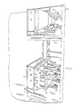
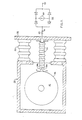
- Figures 1 and 2 show an embodiment of the invention for metal clad or metal enclosed switchgear 10, which includes a metal cabinet or enclosure 12 having tandemly, vertically disposed therein drawout three-phase vacuum circuit interrupter apparatus 14 and 16.
- the front panel 15 of the apparatus may have controls thereon for manually operating the apparatus.
- the lower part cf the apparatus 14 is movably disposed by way of wheels 17 on rails 18 for moving the apparatus 14 into and out of a disposition of electrical contact with live high voltage terminals (not shown) disposed in the rear of the cabinet 12.
- the upper part of the apparatus 16 is movably disposed by way of wheels 19 on rails 20 for moving the upper part of the circuit interrupter apparatus into and out of a disposition of electrical contact with terminals (not shown) in the rear of metal cabinet 12.
- Movable shutters such as shown at 21 are interposed to cover the high voltage terminals in the rear of the cabinet when the circuit interrupters are drawn out for shielding those high voltage terminals from inadvertent contact therewith.
- Barriers 21 are mechanically moved from in front of the aforementioned terminals when the three-phase circuit interrupters 14 and 16 are moved into a disposition of electrical contact with the aforementioned high voltage terminals.
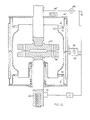
- three-phase circuit interrupter apparatus 14 may include a front portion 24 in which controls and portions of an operating mechanism are disposed and a rear portion 26.
- the front portion 24 is generally a low voltage portion and the rear portion 26 is generally a high voltage portion.
- the high voltage portion 26 is supported by and electrically insulated from the low voltage portion 24 by way of upper and lower insulators 28 and 30, respectively.
- vacuum circuit interrupter bottles 32 Disposed within the high voltage portion 26 are vacuum circuit interrupter bottles 32 which provide the circuit interrupting capability between the three-phase terminals 34 and 36, for example.
- the motion and much of the information for opening and closing the contacts of the vacuum circuit interrupter bottles 32 may be supplied by way of linkages 38 from the front portion 24 of the circuit interrupter apparatus 14.
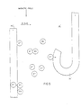
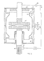
- circuit interrupter bottle 32 may comprise an insulating cylinder 42 capped at either end by electrically conducting circular end caps 44 and 46.
- a vertically movable contact stem 48 On the bottom is shown a vertically movable contact stem 48 and on the top is shown a fixed contact stem 50 which may be brazed, for example, to the aforementioned end plate 44.
- the end caps 44 and 46 are sealingly disposed on the ends of the cylinder 42 at seal regions 52 and 54, as are shown in more detail in Figure 4, for example.
- Longitudinally centrally disposed in the cylinder 42 may be an electrically conducting ring 56, the usefulness of which will be described in more detail hereinafter.
- the cylinder 32 is mounted within the high voltage portion or casing 26 of Figure 2 so that the stationary stem 50 is placed in a disposition of electrical contact with the contact member 34.
- the vertically movable stem 48 is disposed in a disposition of electrical contact with the terminal member 36.
- the operating mechanism 38 of Figure 2 operates to force the vertically movable stem upward and downward when circuit interconnection or disconnection is sought, respectively, between the terminals 34 and 36.
- circuit interrupter bottles 32 each are disposed in the lower circuit interrupter apparatus 14 and in the upper circuit interrupter apparatus 16 to provide two sets of three-phase circuit interruption for two different electrical systems or networks if desired.
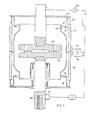
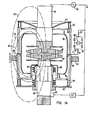
- FIG 4 a sectional view of the vacuum interrupter shown in Figures 2 and 3 is depicted with a schematic electrical circuit connected thereto. Electrically conducting end plates 44 and 46 are interconnected with the insulating barrel 42 at regions 52 and 54, respectively. An appropriate cementing or sealing process is utilized to make the seal vacuum reliable. It is known in the vacuum circuit interrupter art that these seals are sensitive regions which if attacked chemically, thermally or otherwise may break down thus destroying the vacuum integrity of the vacuum interrupter unit 3?. Consequently, shields 70, 74 and 76 are provided for preventing vapor deposition against the inside wall of the insulator 42 and for preventing vapor products and the heat therefrom from degrading the seal in the regions 52 and 54.
- Shield 74 is suspended within the vacuum interrupter unit 32 from the end plate 44 while shield 76 is suspended or supported by the end plate 46.
- the centrally located shield 70 is brazed or otherwise interconnected with an annular ring 56 which is sandwiched in between two portions of the porcelain insulator 42 for support thereby. Consequently, shield 70 is centrally supported away from the region of electrical interruption of the circuit interrupter 32.
- external voltage source 58 which may be the voltage of a network, is interconnected with stem 50 at region 60, for example.
- a resistive element R designated 40 for correspondence with what is shown in Figure 2 is interconnected directly, capacitively or inductively, between the annular ring 56 and a current detection network 64 which may comprise a full wave bridge rectifier having a microammeter 68 disposed to measure the current flowing through the bridge.
- the other side of the bridge or detector circuit 64 is interconnected with the ground or return of the voltage source 58 and with one side of a load LD.
- the other side of the load LD is interconnected with a commutating device 62 for interconnection with the movable stem 48.
- an internal shield 86 for a bellows 84 may also be provided an internal shield 86 for a bellows 84.
- the bellows 84 is expandable with and contractable with the movement of the stem 48 to maintain vacuum integrity. Consequently, the internal portion of the circuit interrupter 32 is normally vacuum tight.
- the vacuum represents a desirable region in which to interrupt current flowing between contacts 80 and 82 as stem 48 moves downwardly (with respect to Figure 4) to cause a separation or gap to exist between contacts 80 and 82.
- the introduction of the vacuum gap between the contacts 80 and 82 causes a diffused arc to exist between the contacts 80 and 82 during the current interrupter process which extinguishes usually on the next current zero of the current.
- the travel of the stem 48 in a downward direction can be relatively small while nevertheless retaining high voltage insulating capability between the open contacts 80 and 82.
- the shields 76, 74 and 70 have rounded or curvilinear end regions thereon to prevent high voltage breakdown therebetween when the contacts 80 and 82 are opened.
- the depression in the end piece 44 is to provide a positive bias against the operation of the stem 48 in the upward direction.
- the force provided against stem 48 tends to be relatively high and therefore the bias of the end plate 44 helps to prevent significant movement of the contact 80 in response thereto.
- a magnet 78 is shown disposed axially around the stem 50 in the depression of the end plate 44.
- this is a permanent magnet, but may in another embodiment of the invention be an electromagnet, and in another embodiment may be a magnet not disposed axially (refer to Fig. 12) and may even be missing from still other embodiments of the invention.
- the purpose of this magnet will be described hereinafter with respect to other figures.
- the high voltage source 58 provides current through stem 50, contact 80, contact 82, stem 48, commutating device 62, and the load LD.
- the load LD is isolated from the high voltage source 58 and no current flows therethrough.
- the detecting device 64 described previously is on the low voltage side of the resistive element R.
- the other side of the resistive element R may be of relatively high potential because of the proximity of the shields 70, 76 and 74 to the contacts 80 and 82.
- the shield 74 for example, on an appropriate half cycle of the voltage source 58 may be at a relatively high voltage.
- a capacitive electrostatic field may exist between the shield 74 and the shield 70 due to the interconnection of the shield 70 through the resistive elements 40, and the bridge circuit 64, to the other side of the voltage source 58.
- the shield 70 when cooperating with the shield 74 or the shield 76, forms an annular region spaced away from the contacts 80 and 82 relative to the available amount of radial distance within the vacuum circuit interrupter 32.
- a pressure detection ion gauge may be utilized in conjunction with the resistive element R and the bridge circuit 64 to determine the amount of vacuum or quality of vacuum within the circuit interrupter 32.
- the ion gauge is such that under appropriate conditions of electrostatic field strength (and in some instances transverse magnetic field strength, such as may be provided by the magnet 78) cold cathode emitted electrons from any of the shields 74, 70 or 76 may interact with gas molecules thus forming ions which impinge any of the shields 70, 74 and 76 to set up current which can be measured by the microammeter 68 to give an indication of the amount of gas within the vacuum circuit interrupter 32. Consequently, this gives an indication of the quality of vacuum within the circuit interrupter 32.
- the magnet 78 operates to cause the electrons to remain in the annular region for a relatively long period of time thus enhancing the opportunity for them to strike even relatively small amounts of gas molecules to set up the aforementioned current.
- the effect of the magnet is not necessary and the magnet may be deleted as it has been found that at certain higher pressures desirable information about the quality of the vacuum within the vacuum interrupter 32 may be obtained because of current flow due to a "glow- discharge" between the shields-
- the current may flow from the voltage source 58, through the stem 50, through the electrically connected end plate 44, through the upper shield 74, via the cold cathode discharge a "glow discharge” to the lower shield 70, the annular ring 56, through the resistor R, the bridge 64, and finally to the other side of the voltage source 58.
- An exemplary plot of current versus pressure is shown, for example, in Figure 6 which will be described hereinafter.
- Figure 5 shows a portion of a shield 70' and a portion of a shield 74' which may also be seen in Figure 8.
- the electrostatic field set up by the high voltage source 58 may draw electrons e away from the plate 70'.
- the transverse magnetic fields designated as such in Figure 5 causes the electrons to take a path which is perpendicular to both the magnetic field and the electrostatic field. This causes the electrons to remain in the region between the two plates 70' and 74' rather than to migrate very quickly to the other plate.
- the electrons will strike some of the gas molecules as mentioned, thus causing other electrons to be given off, thus sustaining the electron density at approximately 10 +10 electrons per cubic centimeter.
- the gas molecules acquire a positive electrical charge when impacted by the electron.
- the charged molecules g + therefore migrate, in this case towards the plate 70', to combine with an electron on the surface of the plate 70' to once again neutralize its charge.
- some of the electrons in the region between the plates 70' and 74' migrate to the plate 74'.
- the net effect of the latter two actions is to produce a net current which is a reliable indication of the number of gas molecules present in the region A'.
- the accurate detection of this current has the effect of indicating the relative vacuum quality of the region A'. Since the region A' is contiguous with the entire region within the circuit interrupter 32 or 32' as the case may be, a reliable indication of the quality of the vacuum in the region of the electrodes 80 and 82 or 80' and 82' as the case may be, is given. As has been mentioned before, this is very desirable.
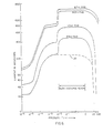
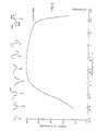
- plots of microampere current produced in a region such as A', or a combination of regions such as A' and B' as shown in Figure 7, versus pressure in torque is given for four different values of a voltage or a.c. source such as 58.
- the voltage values are 2.9 kilovolts RMS, 4.3 kilovolts RMS, 8 kilovolts RMS, and 8.7 kilovolts RMS.
- the amount of gas molecules available for interacting in the ion gauge region such as A' of Fig.
- the detection device is a full-wave bridge rectifier such as is shown at 64, then the increase in the current will be readily seen. However, if the detection device is a half-wave bridge rectifier the curve for 2.9 kilovolts RMS for example will follow a shape more like that shown at 100, which is depicted more accurately in Figure 9.
- One of the advantages of utilizing the shields 70 and 74 for example, or 70 and 76, in determining pressure is the wide range of detection capability, i.e. from approximately 10 -6 Torr to nearly to atmosphere. Of course in the region past 10-3 Torr, the linear relationship changes so that an accurate determination of the amount of vacuum can no longer be determined by reading the current.
- FIG. 9 a plot of the 2.9 KV RMS curve of Figure 6 is shown in detail in the 10 -5 Torr to 10 +2 Torr region.
- the aforementioned curve was produced using only a half-wave bridge rectifier but was also taken utilizing an oscilloscope across a resistive element such as r2 shown in Figure 4.
- the significance is that the wave shapes produced may be detected for various values of pressure current.
- one value of current may be indicative of two different pressures, for example at approximately 10-4 Torr and approximately 100 Torrs, a current of 180 microamps is detected.
- One person reading 180 microamperes on the ammeter would not know whether the pressure inside the circuit interrup- ter was an acceptable 10 -4 Torr or an undesirable 100 Torr.
- the difference is such that it can easily be determined in which portion of the curve one is observing current, which may mean the difference between allowing a circuit interrupter to open in a perfectly acceptable vacuum or in a very undesirable high pressure region.
- FIG. 7 still another embodiment of the invention is shown in which a vacuum circuit interrupter and an associated external voltage source detector system and load are also depicted.
- the magnet of the embodiment of Figure 4 is purposely deleted.
- the shield arrangement represented at 70', 74' and 76' is different from that shown at 70, 74 and 76 in Figure 4.
- the shield 70' axially overlaps shields 74' and 76' in the embodiment of Figure 7 whereas that is not the case in the embodiment of Figure 4. Consequently, the annular regions A' and B' are slightly different in volume and shape in the embodiment of Figure 7 than the annular regions A and B in the embodiment of Figure 4.
- the operation is essentially the same except for the fact that the embodiment of Figure 7 is of the type which is used primarily in the region depicted in Figure 6 between 10" Torr and 100 Torr. That is to say, in the embodiment of Figure 7 the defecting device 64 is utilized to detect whether there has been a failure of vacuum or not.
- FIG 8 still a further embodiment of the invention is shown which utilizes principles from the embodiments of the invention shown in Figures 4 and 7.
- the embodiment of Figure 8 shows the axially overlapping shields 70', 74' and 76' which were previously shown in the embodiment of Figure 7 and furthermore shows the magnet 78' which was previously shown in the embodiment of Figure 4.
- the end plate 44' is not depressed as the end plate 44 is in Figure 4.
- it is to be reccg- nized that this is a matter of design choice in this particular embodiment of the invention and that neither the depressed end plate 44 nor the non-depressed end plate 44' is limiting.
- the resistive element R or 40 as is shown in Figure 4 for example is disposed within a porcelain or other good insulator cylindrical casing to provide high voltage insulation along the outer surface thereof between the high voltage section and the low voltage section 24. It will be recalled that the high voltage section 26 includes the vacuum interrupter 32 whereas the low voltage section 24 includes the detectcr 64.
- fork-like electrically conducting tynes protrude out of one end of the insulated resistive element 40 to make forceful tangential electrical contact at the points X-X with the shield ring 56 to complete the necessary electrically conducting path between the detector 64 and the circuit interrupter 32.
- the tynes are identified as 98a and 98b.
- the tynes 98a and 98b flex as the resistive element R is brought into contact with the ring 56 to increase the contact pressure and thus reduce the contact resistance.
- a magnet 78" is radially offset from the stem so that the produced magnetic field may be non-symmetrical. This means that the magnet 78" need not enclose or encircle the stem. This leads to simpler construction of the circuit interrupter.
- a magnet 78"' is placed inside of the circuit interrupter.
- the particular kind of vacuum circuit interrupter utilized is non-limiting provided there are at least one set of shields in a path of electrical conduction and where one of the shields makes an interconnection (not necessarily ohmic) with a voltage detection network for circuit completion with the high voltage source which is interconnected with the other shield.
- the bridge circuit 64 may be replaced by any suitable measuring circuit.
- the invention is not limited to use in three-phase electrical operation. It may be useful in single-phase electrical operation or other poly-phase electrical operation or even DC electrical operation. The principles taught herein may be used with other types of vacuum devices such as triggered gaps, switches and the like.
- Figure 14 shows an embodiment in which a "hoop" type magnet 110 is utilized instead of the "pancake” type magnet 78.
- the north pole is at the top of the magnet 110 relative to Figure 14, and the south pole was shown at the bottom.
- Representative magnetic flux lines 112, 114, 116 are shown.
- magnetic flux lines 112, 114, 116 are shown.
- the "hoop" type magnet 110 may be secured to the casing 42 by any convenient manner, an epoxy glue 118 being shown as an illustrative example.
- the apparatus taught with respect to the embodiments of this invention has many advantages.
- One advantage lies in the fact that the "Magnetron" or “Penning” type ion ' detection gauge is operable over an extremely wide range of pressures for providing useful data concerning the status of vacuum within a circuit interrupter or similar device.
- Another advantage lies in the fact that the utilization of the end shields of a vacuum circuit interrupter helps to maintain high voltage isolating characteristics.
- the present invention does not require the addition of further leak regions than are already present in the vacuum interrupter for vacuum detection and also the present invention utilizes existing vacuum interrupter geometry for reduced costs.
- Other advantages lie in the fact that the present device utilizes a.c. power, requires no further power than is available to the interrupter (i.e., no separate power supply), and is extremely sensitive over a wide pressure range.
Landscapes
- Measuring Fluid Pressure (AREA)
- High-Tension Arc-Extinguishing Switches Without Spraying Means (AREA)
- Physical Vapour Deposition (AREA)
- Switches With Compound Operations (AREA)
- Switches Operated By Changes In Physical Conditions (AREA)
Applications Claiming Priority (4)
| Application Number | Priority Date | Filing Date | Title |
|---|---|---|---|
| US06/226,332 US4403124A (en) | 1981-01-19 | 1981-01-19 | Vacuum circuit interrupter with insulated vacuum monitor resistor |
| US06/226,331 US4440995A (en) | 1981-01-19 | 1981-01-19 | Vacuum circuit interrupter with on-line vacuum monitoring apparatus |
| US226331 | 1981-01-19 | ||
| US226332 | 1981-01-19 |
Publications (2)
| Publication Number | Publication Date |
|---|---|
| EP0056722A2 true EP0056722A2 (de) | 1982-07-28 |
| EP0056722A3 EP0056722A3 (de) | 1982-08-04 |
Family
ID=26920433
Family Applications (1)
| Application Number | Title | Priority Date | Filing Date |
|---|---|---|---|
| EP82300257A Ceased EP0056722A3 (de) | 1981-01-19 | 1982-01-19 | Vakuumschalter mit eingebauter Überwachungsvorrichtung |
Country Status (9)
| Country | Link |
|---|---|
| EP (1) | EP0056722A3 (de) |
| JP (1) | JPH04102531U (de) |
| AR (1) | AR229688A1 (de) |
| AU (1) | AU555075B2 (de) |
| BR (1) | BR8200112A (de) |
| ES (1) | ES8305155A1 (de) |
| HU (1) | HU189555B (de) |
| MX (1) | MX151605A (de) |
| NO (1) | NO820118L (de) |
Cited By (6)
| Publication number | Priority date | Publication date | Assignee | Title |
|---|---|---|---|---|
| EP0060054B1 (de) * | 1981-03-06 | 1985-06-05 | Kabushiki Kaisha Toshiba | Vakuumschalter |
| EP0150389A1 (de) * | 1983-12-27 | 1985-08-07 | Siemens Aktiengesellschaft | Vorrichtung zum Messen des Innendrucks eines betriebsmässig eingebauten Vakuumschalters |
| GB2154065A (en) * | 1984-02-02 | 1985-08-29 | Westinghouse Electric Corp | Vacuum switch |
| EP0758794A1 (de) * | 1995-08-10 | 1997-02-19 | Siemens Aktiengesellschaft | Vorrichtung zur Überwachung des Vakuums eines Vakuumschalters |
| EP3190601A4 (de) * | 2014-09-01 | 2018-06-06 | Hitachi Industrial Equipment Systems Co., Ltd. | Diagnosevorrichtung für vakuumventildruck oder vakuumventilvorrichtung |
| CN112820580A (zh) * | 2020-12-30 | 2021-05-18 | 河北电力装备有限公司 | 一种背带式横磁场直流电流转移装置及其应用 |
Families Citing this family (2)
| Publication number | Priority date | Publication date | Assignee | Title |
|---|---|---|---|---|
| MX347690B (es) * | 2013-07-02 | 2017-05-09 | Indelcon 2007 S L | Dispositivo de proteccion contra sobre intensidades en circuitos electricos y utilizaciones de dicho dispositivo en un eslabon fusible y en un fusible limitador asociado asi como en fusibles para proteccion de semiconductores. |
| KR102566366B1 (ko) * | 2021-12-26 | 2023-08-10 | 이인표 | 진공인터럽터 진공도 감시장치 및 이를 이용한 감시방법 |
Family Cites Families (7)
| Publication number | Priority date | Publication date | Assignee | Title |
|---|---|---|---|---|
| US2864998A (en) * | 1957-07-08 | 1958-12-16 | Gen Electric | Pressure measuring arrangement for a vacuum circuit interrupter |
| US3263162A (en) * | 1962-04-20 | 1966-07-26 | Gen Electric | Apparatus and method for measuring the pressure inside a vacuum circuit interrupter |
| US3403297A (en) * | 1966-03-17 | 1968-09-24 | Gen Electric | Vacuum-type circuit interrupter with pressure-monitoring means |
| US3575656A (en) * | 1968-08-30 | 1971-04-20 | Ite Imperial Corp | Method and apparatus for measuring pressure in vacuum interrupters |
| JPS48104077A (de) * | 1972-04-17 | 1973-12-26 | ||
| JPS4933168A (de) * | 1972-07-28 | 1974-03-27 | ||
| US4103291A (en) * | 1976-09-30 | 1978-07-25 | Howe Francis M | Leak sensor and indicating system for vacuum circuit interrupters |
-
1981
- 1981-12-30 AU AU79091/81A patent/AU555075B2/en not_active Ceased
-
1982
- 1982-01-11 BR BR8200112A patent/BR8200112A/pt unknown
- 1982-01-13 MX MX190956A patent/MX151605A/es unknown
- 1982-01-15 NO NO820118A patent/NO820118L/no unknown
- 1982-01-18 ES ES508829A patent/ES8305155A1/es not_active Expired
- 1982-01-19 EP EP82300257A patent/EP0056722A3/de not_active Ceased
- 1982-01-19 AR AR288168A patent/AR229688A1/es active
- 1982-01-19 HU HU82139A patent/HU189555B/hu not_active IP Right Cessation
-
1991
- 1991-06-17 JP JP1991053565U patent/JPH04102531U/ja active Pending
Cited By (9)
| Publication number | Priority date | Publication date | Assignee | Title |
|---|---|---|---|---|
| EP0060054B1 (de) * | 1981-03-06 | 1985-06-05 | Kabushiki Kaisha Toshiba | Vakuumschalter |
| EP0150389A1 (de) * | 1983-12-27 | 1985-08-07 | Siemens Aktiengesellschaft | Vorrichtung zum Messen des Innendrucks eines betriebsmässig eingebauten Vakuumschalters |
| US4672323A (en) * | 1983-12-27 | 1987-06-09 | Siemens Aktiengesellschaft | Device for measuring the internal pressure of an operationally built built-in vacuum switch |
| GB2154065A (en) * | 1984-02-02 | 1985-08-29 | Westinghouse Electric Corp | Vacuum switch |
| EP0758794A1 (de) * | 1995-08-10 | 1997-02-19 | Siemens Aktiengesellschaft | Vorrichtung zur Überwachung des Vakuums eines Vakuumschalters |
| US5739419A (en) * | 1995-08-10 | 1998-04-14 | Siemens Aktiengesellschaft | Apparatus for monitoring the vacuum of a vacuum switch |
| EP3190601A4 (de) * | 2014-09-01 | 2018-06-06 | Hitachi Industrial Equipment Systems Co., Ltd. | Diagnosevorrichtung für vakuumventildruck oder vakuumventilvorrichtung |
| CN112820580A (zh) * | 2020-12-30 | 2021-05-18 | 河北电力装备有限公司 | 一种背带式横磁场直流电流转移装置及其应用 |
| CN112820580B (zh) * | 2020-12-30 | 2023-01-24 | 河北电力装备有限公司 | 一种背带式横磁场直流电流转移装置及其应用 |
Also Published As
| Publication number | Publication date |
|---|---|
| ES508829A0 (es) | 1983-03-16 |
| JPH04102531U (ja) | 1992-09-03 |
| EP0056722A3 (de) | 1982-08-04 |
| AR229688A1 (es) | 1983-10-31 |
| NO820118L (no) | 1982-07-20 |
| HU189555B (en) | 1986-07-28 |
| MX151605A (es) | 1985-01-07 |
| ES8305155A1 (es) | 1983-03-16 |
| AU555075B2 (en) | 1986-09-11 |
| AU7909181A (en) | 1982-07-29 |
| BR8200112A (pt) | 1982-11-03 |
Similar Documents
| Publication | Publication Date | Title |
|---|---|---|
| US4440995A (en) | Vacuum circuit interrupter with on-line vacuum monitoring apparatus | |
| US4403124A (en) | Vacuum circuit interrupter with insulated vacuum monitor resistor | |
| US6426627B2 (en) | Vacuum switch including vacuum-measurement devices, switchgear using the vacuum switch, and operation method thereof | |
| EP0079181B1 (de) | Vakuum-Überwachungsgerät für Vakuum-Schalter und seine Verwendung | |
| EP0944105B1 (de) | Vakuumisolierter Schaltapparat | |
| US6498314B2 (en) | Vacuum switch and vacuum switchgear using the same | |
| US4163130A (en) | Vacuum interrupter with pressure monitoring means | |
| EP0036760B1 (de) | Vakuum-Schalter-System | |
| US10199183B2 (en) | Vacuum-insulated switch enabling testing of the vacuum, switch assembly, and testing method | |
| US3071667A (en) | Vacuum-type circuit interrupter | |
| EP0056722A2 (de) | Vakuumschalter mit eingebauter Überwachungsvorrichtung | |
| US3594754A (en) | Pressure measurement arrangements for a vacuum-type circuit interrupter | |
| US2864998A (en) | Pressure measuring arrangement for a vacuum circuit interrupter | |
| CN1125978C (zh) | 放电型真空灭弧室真空度在线检测方法 | |
| US4491704A (en) | Vacuum circuit interrupter having vacuum monitoring apparatus | |
| EP0516422A2 (de) | Vakuummeter | |
| US3263162A (en) | Apparatus and method for measuring the pressure inside a vacuum circuit interrupter | |
| US4471309A (en) | Vacuum detector | |
| Okawa et al. | Reliability and field experience of vacuum interrupters | |
| EP0098523B1 (de) | Vakuummonitor für Vakuumschalter | |
| JP2885233B2 (ja) | 真空バルブ形開閉装置の真空度低下検出装置 | |
| US3654520A (en) | High voltage surge diverter | |
| US4276455A (en) | Vacuum envelope for current limiter | |
| JP2705266B2 (ja) | 真空バルブ形開閉装置の真空度低下検出装置 | |
| Graneau et al. | Voltage surge performance of vacuum-insulated cryo-cable |
Legal Events
| Date | Code | Title | Description |
|---|---|---|---|
| PUAI | Public reference made under article 153(3) epc to a published international application that has entered the european phase |
Free format text: ORIGINAL CODE: 0009012 |
|
| PUAL | Search report despatched |
Free format text: ORIGINAL CODE: 0009013 |
|
| AK | Designated contracting states |
Designated state(s): BE CH DE FR GB IT NL SE |
|
| AK | Designated contracting states |
Designated state(s): BE CH DE FR GB IT NL SE |
|
| 17P | Request for examination filed |
Effective date: 19830204 |
|
| STAA | Information on the status of an ep patent application or granted ep patent |
Free format text: STATUS: THE APPLICATION HAS BEEN REFUSED |
|
| 18R | Application refused |
Effective date: 19860721 |
|
| RIN1 | Information on inventor provided before grant (corrected) |
Inventor name: LANGE, WILLIAM J. Inventor name: PERKINS, JOHN FRANK Inventor name: DAVIES, NORMAN Inventor name: GOSSER, ROBERT BENTON |